S. E. Alavi, I. S. Amiri, M. R. K. Soltanian, R. Penny, A. S. M. Supa’at, H. Ahmad, "Multiwavelength generation using an add-drop microring resonator integrated with an InGaAsP/InP sampled grating distributed feedback," Chin. Opt. Lett. 14, 021301 (2016)
Copy Citation Text
A system of an add-drop microring resonator integrated with a sampled grating distributed feedback (SG-DFB) is investigated via modeling and simulation with the time-domain traveling wave (TDTW) method. The proposed microring resonator comprises a waveguide integrated with an InGaAsP/InP SG-DFB, and the waveguide consists of a silicon core having a refractive index of 3.48 and Kerr coefficient of . The SG-DFB consists of a series of grating bursts that are constructed using a periodic apodization function with a burst spacing in the grating of 45 μm, a burst length of 5 μm, and 10 bursts across the total length of the SG-DBR. Transmission results of the through and drop port of the microring resonator show the significant capacity enhancement of the generated center wavelengths. The -factor of the microring resonator system, defined as the center wavelength () divided by 3 dB FWHM, without and with integration with the SG-DFB is calculated as and , respectively. Analysis of the dispersion of the system reveals that increasing the wavelength results in a decrease of the dispersion. The higher capacity and efficiency are the advantages of integrating the microring resonator and the InGaAsP/InP SG-DFB.
Researchers have been actively investigating wavelength-selective reflective elements based on microring resonators (MRs)[1] in recent years, with experimental demonstrations of resonance splitting and enhanced notch depth in MRs due to mutual mode coupling. The free spectral range is usually large for small-radius rings, and this limits the number of channels that can be adopted for operation[2]. Split resonances provide more wavelengths for signal processing and thus increase the system capacity. Integration of inline reflectors into planar optical circuits is important for several reasons[3]; integrated reflectors can be much smaller than corresponding fiber devices, can be fabricated in a variety of materials with special nonlinear functionality or with specific dispersion properties, and can be combined on a single chip with additional photonic devices such as modulators, couplers, or sources[4]. However, integration of sample gratings within a planar waveguide optical circuit is difficult due to the high-resolution lithography required over large areas to achieve high reflection efficiency and low scattering loss[5]. This is especially the case with integrated geometries that necessitate aperiodic gratings[6,7]. As an alternative to integrated sample gratings, the microring-based reflector presents several advantages including increased flexibility[8], compactness allowing for simpler and more controlled fabrication, and the possibility of incorporation with additional photonic devices[9,10].
Silicon photonics has become one of the most promising photonic integration platforms over the last few years[11–13], and passive silicon waveguide structures have shown an unprecedented reduction in footprint of the waveguides, and especially for wavelength-selective devices[14,15]. Experimentally, the integration technology is the planar fabrication process, which has been well studied and finds a host of applications in both telecommunications and sensing[13]. Ring resonators play an important role in the success of silicon photonics since ring resonators of silicon can be constructed at an unprecedented small size[16,17]. Integrated optic MRs have exhibited attractive filter and switching behavior in connection with extremely small chip-areas for single functional elements[18]. These ring resonators behave as spectral filters that can be used for applications in optical communication, particularly wavelength division multiplexing (WDM)[19,20]. An integrated add-drop MR has been proposed in this paper. This proposed resonator comprised a waveguide integrated with a sampled grating distributed feedback (SG-DFB) made of an InGaAsP/InP semiconductor. The time-domain traveling wave (TDTW) method was employed for modeling and simulating the proposed MR integrated system. Silicon photonic wires represent an ideal platform for nonlinear behavior because silicon exhibits a variety of strong nonlinear effects, such as Kerr nonlinearity[21–24]. Maximizing the nonlinearity required optimization of the nonlinear parameter whereby the effective area of nonlinear interaction depends on the waveguide geometry[25].
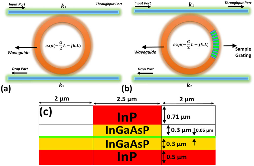
The add-drop MR system illustrated in Fig. 1(a) provided the foundation for the proposed integrated resonator and SG-DFB design shown in Fig. 1(b). This latter design guaranteed a monomodal propagation of light in the waveguide and very low bending losses as a result of efficient confinement in the resonator. The waveguide had a silicon core with a refractive index of 3.48 surrounded by a silicon oxide bottom cladding ( of 1.44) and a low refractive index top cladding (oxide or air). A schematic of the SG-DFB structure is shown in Fig. 1(c). The utilized SG-DFB layer sequence from bottom to top, with corresponding layer thickness and refractive index, was InP substrate (0.5 μm) (), InGaAsP (0.3 μm) (), InGaAsP etch stop layer (0.05 μm) (), InGaAsP (0.3 μm) (), and InP cap (0.71 μm) (). The center wavelength is 1.55 μm.
Sign up for Chinese Optics Letters TOC. Get the latest issue of Chinese Optics Letters delivered right to you!Sign up now
Figure 1.Schematic diagram of (a) an add-drop MR system without integration with an SG-DFB, (b) an add-drop MR system integrated with an SG-DFB, and (c) the SG-DFB structure.
The input optical field () of the Gaussian pulse (1 mW power) is given by[26]where the pulse width , which is related to the pulse full width at half maximum by , increases with (i.e., a broadened pulse) according to and consequently the peak power changes due to group velocity dispersion (GVD) are given by
In Eqs. (2) and (3), the quantity is the dispersion length of the Gaussian pulse and is the second-order coefficient term of the Taylor expansion of the propagation constant. For the soliton propagation, a balance should be achieved between the dispersion length () and the nonlinear length , such that , where , is the length scale over which dispersion or nonlinear effects make the beam wider or narrower[27–29]. When a Gaussian pulse propagates within the MR, resonant output is formed for each round trip[30–32]. The normalized output of the light field is defined as the ratio between the output and input fields ( and ) in each round trip. Thus, this normalized output can be expressed as[33–35]where is the coupling coefficient, represents a round-trip loss coefficient; , and are the linear and nonlinear phase shifts, respectively; is the Kerr coefficient or nonlinear index; the fractional coupler intensity loss is ; is the linear absorption coefficient[36–38]. The Kerr coefficients for the silicon and InGaAsP waveguides are and at 1.55 μm, respectively[39,40]. The effective areas for the silicon and InGaAsP waveguides are calculated as and μ, respectively; therefore the nonlinear phase shifts of the two waveguides are
The parameters of the proposed add-drop MR are presented in Table 1.
The presented silicon MR waveguide is integrated with the InGaAsP/InP SG-DFB. However, it is challenging to couple light directly from a silicon waveguide to a different waveguide such as InGaAsP/InP. In general cases, this integration method usually causes a large insertion loss due to the small overlap of the mode profile and index mismatch. One effective way to avoid these losses is to fabricate the waveguide size of the silicon MR comparable to the InGaAsP/InP waveguide. In the presented design, we have considered the cross sectional profiles of the silicon micoring resonator and the InGaAsP/InP SG-DFB as the same; therefore, it will significantly reduce the interface mode mismatch. Also, we have selected the silicon and InGaAsP materials that have a low contrast between the refractive indices as cores (silicon and InGaAsP have refractive indices of 3.48 and 3.31, respectively) for the MR and SG-DFB waveguides to avoid the index mismatch.
The SG-DBR consisted of a series of grating bursts. For simplicity, this grating is considered to be placed symmetrically along the ring’s circumference. The total circumference of the ring resonator was 1105 μm and so the ring had a radius of 176 μm. The grating was periodically suppressed so that only short bursts of gratings remained. The burst spacing in the grating was 45 μm, the burst length was 5 μm, and the total grating length was 455 μm. Therefore, there were 10 bursts within the SG-DFB[41]. The refractive indices of the alternative materials in the grating were 3.18 and 3.31 for InP and InGaAsP, respectively.
The bursts were achieved using a periodic apodization function. Optical signals propagating inside the ring resonator were injected into the SG-DFB so that their reflection spectra could be measured. Accordingly, the periodic resonances in each reflection spectrum could be obtained along with a comb of resonances resulting from (the Fourier transform of) the periodic grating bursts.
The fabrication of apodized Bragg gratings has raised much interest because these objects have reduced reflectivity at sidelobes, which in turn increases the quality of the optical filters and improves the dispersion compensation by simultaneously reducing the group-delay ripples. The sideband reflection peaks can be problematic for many applications, causing cross talk in WDM systems, instabilities in -switched fiber lasers, and linewidth broadening in high-power fiber lasers. To eliminate these unwanted sidebands, it is necessary to fabricate gratings with an apodized profile, where the grating strength varies as a function of length and is typically weaker at both ends of the grating. Apodized gratings offer a significant improvement in sidelobe suppression while maintaining reflectivity and a narrow bandwidth. The two functions typically used to apodize a DFB are Gaussian and raised cosine. The introduced model allows gratings to be apodized and also facilitates the introduction of phase shifts between gratings in adjacent sections. In this research, the phase shift is zero. Figure 2(a) shows the employed SG-DFB structure, and Fig. 2(b) shows the number of used bursts versus the grating length.
Figure 2.(a) SG-DFB structure with burst length μ, burst spacing μ, sample grating length μ, and number of bursts ; (b) grating length versus number of bursts.
The Picwave photonic integrated circuit (PIC) simulator is used for the presented design using time-domain model. The system of the MR before and after integration with the SG-DFB is shown in Figs. 1(a) and 1(b), respectively, where the total length of the whole system in both cases is constant and equal to 1105 μm. The mode-propagation profile of the input pulse within the silicon waveguide is shown in Fig. 3. The effective index is 3.33 and the effective area is μ. The coupling loss of 4 dB is achieved due to the integration of silicon and InGaAsP/InP SG-DFB.
Figure 3.Mode propagation profile of the silicon waveguide with a length of 650 μm. (a) 2D view, (b) 3D view, (c) cross section view, (d) 3D view of the propagation respect to the cross section of the silicon waveguide; the effective index is 3.33 and the effective area is μ.
The mode-propagation profile of the input pulse within the SG-DFB is shown in Fig. 4. The effective index is 3.25 and the effective area is μ.
Figure 4.Mode propagation profile of the SG-DFB with a length of 455 μm. (a) 2D view, (b) 3D view, (c) cross section view, (d) 3D view of the propagation respect to the cross section of the SG-DFB; the effective index is 3.25 and the effective area is μ.
Figures 4(c)–4(d) show the cross section of the SG-DFB and the propagating profile, respectively. The time domain’s output signals of the drop port from the MR before and after the integration with the SG-DFB are shown in Figs. 5(a) and 5(b), respectively.
Figure 5.Time domain output signals from the drop port of the add-drop MR (a) without integration with the SG-DFB, , and (b) with integration with the SG-DFB, .
The throughput output signals of the add-drop MR are shown in Fig. 6, where Figs. 6(a) and 6(b) show the output signals for the systems shown in Figs. 1(a) and 1(b), respectively. The total length of both systems was maintained as constant. As can be seen from Fig. 6(b), the multiple signals achieved a higher number of center wavelengths when the MR was integrated with the SG-DFB. The finesse (3 dB FWHM/FSR) of the two cases were 272.5 and 196.3, respectively. The -factor of the system, which is defined as center wavelength () divided by 3 dB FWHM or FWHM, was calculated as and for the two systems, respectively.
Figure 6.Multiple center wavelength output results from the throughput port of the add-drop MR when (a) the add-drop MR is not integrated with the SG-DFB [Fig. 1(a)], , and ; and (b) the add-drop MR is integrated with the SG-DFB [Fig. 1(b)], , and .
Filters, switches, and other photonic devices are required to have flat-top spectral passbands with steep edges in order to achieve a uniform intensity distribution and to reduce interchannel interference in optical communication networks and on-chip interconnects. Although flat-top passbands with steep edges can be achieved in MR devices by accurately controlling the ring diameters, coupling coefficients between rings and waveguides, as well as the number of MRs.
The drop port output signals are shown in Fig. 7, where Fig. 7(a) corresponds to drop port output signals without SG-DFB integration and Fig. 7(b) corresponds to drop port output signals with SG-DFB integration.
Figure 7.Drop port output signals (a) with no SG-DFB integration, , and ; (b) after the add-drop MR is integrated with the SG-DFB, and .
The dispersion of the drop port output signals reference to the input port within the range of 350 nm, corresponding to the system shown in Fig. 1(a), are shown in Figs. 8(a) and 8(b) for the case where the SG-DFB is not integrated with the add-drop MR. Figure 8(c) shows the dispersion of the drop port output signals referenced to the input pulse for the case where the SG-DFB is integrated with the add-drop MR.
Figure 8.Dispersion of the drop port output signals for (a) an add-drop MR without the SG-DFB [Fig. 1(a)], (b) versus wavelength, and (c) an add-drop MR integrated with the SG-DFB [Fig. 1(b)].
It can be seen from Fig. 8(c) that the dispersion decreases as the wavelength increases. The graph in Fig. 8(c) displays a smoother dispersion in comparison to that of Fig. 8(a).
In conclusion, a proposed system of an add-drop MR integrated with an SG-DBF that is made of InGaAsP/InP semiconductor is described. The TDTW method is used to model and simulate the MR integrated with the InGaAsP/InP SG-DFB. The propagation of an input Gaussian pulse within the add-drop MR is investigated for the two cases of without and with integrated SG-DFB. When the input propagates within the integrated system, the reflection from the bursts grating goes through constructive and destructive interferences with the original signals from the add-drop MR. This affects the outputs and the constructive interferences cause the generation of multiple center wavelengths and thus higher capacity. The advantage of the integration is to increase the capacity of the system via generation of multiple center wavelengths, and has application for capacity enhancements within communication systems in WDM optical networks. The system of the add-drop MR integrated with the SG-DFB shows better performance and a higher -factor compared to the system without SG-DFB. These results provide evidence that an integration of an SG-DFB in an add-drop MR system, which allows for signals with higher efficiency, can be considered for deployment in optical communication systems to enhance capacity.
[25] C. Koos, P. Vorreau, P. Dumon, R. Baets, B. Esembeson, I. Biaggio, T. Michinobu, F. Diederich, W. Freude, J. Leuthold. National Fiber Optic Engineers Conference, PDP25(2008).
S. E. Alavi, I. S. Amiri, M. R. K. Soltanian, R. Penny, A. S. M. Supa’at, H. Ahmad, "Multiwavelength generation using an add-drop microring resonator integrated with an InGaAsP/InP sampled grating distributed feedback," Chin. Opt. Lett. 14, 021301 (2016)