Shiwei Zhang, Hao Chen, Zuowei Xu, Congxian Wu, Kaijun Che, Hongyan Fu. Microwave signal generation based on frequency multiplication with fiber ring loop modulation and microwave photonic filters[J]. Chinese Optics Letters, 2015, 13(Suppl.): S20601
Copy Citation Text
In this Letter, microwave generation based on frequency multiplication with fiber ring loop modulation and microwave photonic filters is proposed and experimentally demonstrated. High-order microwave harmonics can be generated and enhanced by the fiber ring loop modulation formed by incorporating a Mach–Zehnder modulator (MZM) into a fiber ring structure. Cascaded fiber ring based microwave photonic filters (FRMPFs) are adopted to filter out the desirable harmonics. In our work, with a driving signal of 2.835 GHz, the fourth-order harmonic with a frequency of 11.34 GHz is generated by using two cascaded FRMPFs.
Photonic generation of microwave signals has been studied intensively during the last few years, due to their capability of generating high-quality microwave signals with high quality and wideband tunability[1–3]. A number of methods have been proposed for microwave signal generation with the photonic method, such as signal generation by using a four-wave mixing effect[4], external modulation[5–8], beating of single-longitudinal-mode dual-wavelength fiber lasers[9–11], optical injection locking (OIL)[12], optical phase-lock loop (OPLL)[13,14], optoelectronic oscillator[15–17], and so on. Among these techniques, the characteristics of the generated signals with the external modulation method are primarily determined by the quality of the low-frequency driving signals, thus it shows great advantages over other techniques, such as high stability, large tuning range, high efficiency, and ease of implementation. A numbers of microwave signal generation techniques based on external modulation have been proposed. Zhang et al. have proposed a microwave frequency quadrupler using two cascaded Mach–Zehnder modulators (MZMs)[5]. Li et al. have demonstrated the generation and transmission of microwave signals by cascading a phase modulator (PM) and a MZM[6]. In both techniques, two or several modulators are required to generate high-order harmonics. Song et al. have proposed tunable microwave signal generation by using an optical comb and arrayed waveguide gratings (AWGs), in which a PM and nonlinear fiber have been utilized to realize the optical comb and the AWGs perform the optical filtering to select desirable optical comb lines to beat on the detector[18]. In this approach, one PM is used, but a coil of nonlinear fiber is required for generating the optical comb; furthermore, optical filters–AWGs have been used to perform the optical filtering, which is complex and expensive. Microwave signal generation using a MZM and no optical filtering has been demonstrated[19]; however, a specially designed MZM (one main MZM with two sub-MZMs embedded in each arm) is utilized, and the bias voltage must be carefully controlled.
In this Letter, we propose and demonstrate a simple and cost-effective technique to generate high-frequency microwave signals based on fiber ring loop modulation and microwave photonic filters. The fiber ring loop modulation consists of an optical coupler (OC), a MZM, an erbium-doped fiber amplifier (EDFA), and a tunable optical phase shifter (TOPS). The low-frequency driving signal is modulated via the MZM in the fiber ring loop, and due to the recirculating modulation and the power compensation by the EDFA in the fiber ring loop, high-order harmonics can be generated and enhanced. By beating these harmonics on the photodiode (PD), high-frequency microwave harmonic signals which are integral multiples of the low-frequency driving signal can be generated. Cascaded fiber ring based microwave photonic filters (FRMPFs) have been employed to select harmonics with desirable frequencies. The characteristics of these FRMPFs, such as fiber ring length, coupling ratio, and so on, can be designed and adjusted to obtain the proper filtering frequency response, i.e., the free-spectrum range, and the suppression ratio. In our work, by using two cascaded FRMPFs composed of OCs with a coupling ratio of and proper lengths, the fourth-order harmonic with a harmonic suppression ratio of more than 10 dB has been generated, whereas other harmonics with lower frequencies are suppressed.
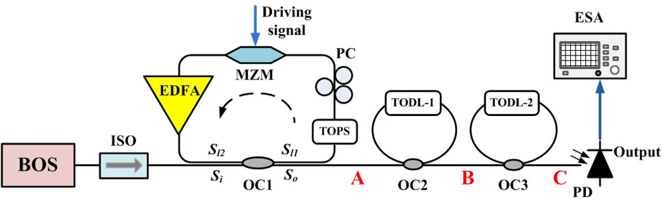
A schematic of the proposed microwave signal generation approach is shown in Fig. 1. The light from a broadband optical source (BOS; QPHOTONICS QSDM-1550-15; central wavelength, ; bandwidth, ) is launched into the fiber ring loop after the optical isolator (ISO). The fiber ring loop is composed of the OC1, a polarization controller (PC), a MZM (JDSU, 20 GHz), an EDFA (Amonics, AEDFA-PA-25), and a TOPS to introduce a proper additional phase shift for the fiber ring loop modulation[20–22]. One output of OC1 is connected to the TOPS, PC, and then the MZM, which is followed by an EDFA to compensate the round-trip loss of the fiber ring loop. The output of the EDFA is connected with one input of OC1. The other input and output ports are taken as the input and output of the fiber ring loop. The driving microwave signal with low frequency from the signal generator (Agilent E4421B) is modulated onto the lightwave via the MZM in the fiber ring loop. Thanks to the recirculating modulation of the fiber ring loop, the high-order harmonics can be generated and greatly enhanced. When a driving microwave signal with a frequency of 1 GHz is applied on the MZM, we connected the PD (Optilab PD-30, 60 kHz to 30 GHz) at Point A, and measures the spectrum of the generated harmonics with an electronic spectrum analyzer (ESA; HP8593E, 9 kHz to 22 GHz), which is shown in Fig. 2(b). One can observe that by using the fiber ring loop modulation, higher-order harmonics have been generated and enhanced, compared with the spectrum of direct modulation by a MZM (which is measured after an EDFA with the same optical power launched into the PD) as shown in Fig. 2(a).
Sign up for Chinese Optics Letters TOC. Get the latest issue of Chinese Optics Letters delivered right to you!Sign up now
Figure 1.Schematic diagram of the proposed microwave signal generation approach.
After the fiber ring loop modulation, the modulated light is sent to the cascaded FRMPFs. As shown in Fig. 1, the FRMPF is formed by connecting one of the output ports with one input port of the OC, whereas the other input port and output port of the OC are taken as the input and output of the filter. A tunable optical delay line (TODL; General Photonics MDL-002, 0–560 ps, accuracy 3 μm) is incorporated to adjust the length of the fiber ring. As the length of the fiber ring is much longer than the coherent length of the optical source, there is a linear relationship between the input and output microwave signals, and the filtering system can be considered as a linear system[23].
The typical frequency response of a FRMPF is shown as the black line in Fig. 3, which exhibits a periodic frequency response and its free-space range (FSR) can be expressed as where c is the velocity of the light in vacuum, and n and L stand for the refractive index and length of the fiber ring, respectively.
Figure 3.Schematic diagram of filtering strategy based on the FRMPFs.
Our filtering strategy is shown as Fig. 3, from which one can see that, when the first-order harmonic is located at the notch point of the FRMPF, i.e., , , all the odd number of harmonics (shown as red arrows) will locate at notch points, whereas all the even number of harmonics (shown as blue arrows) will meet the peak points. In this way, by using cascaded FRMPFs, the odd harmonics can be filtered out and the even harmonics remain, such that the even harmonic with a desirable frequency can be obtained. From Eq. (1), one can see that by tuning the TODL in the FRMPF, the filter’s FSR can easily tuned, and thus the notch points of the FRMPF can meet with the odd harmonics.
In our work, we have used an OC with a coupling ratio of as the OC1 to form the fiber ring loop modulation. The bias voltage of the MZM is set at 5.2 V, and the current of the EDFA is set to be 122 mA to compensate the round-trip loss of the fiber ring loop. The gain of the EDFA must be carefully adjusted to satisfy the condition to achieve the best compensation performance, where is the gain of the EDFA and is the total loss of the ring introduced by the coupling ratio of OC, the insertion loss of modulator, and other components. If the gain of the EDFA is larger than the loss, the lasing condition will be satisfied, which will introduce additional noise for the microwave generation system. In our work, a BOS is used as the optical source, because besides its advantage of low cost, its coherent length is much smaller than the length of the fiber ring, which guarantees a linear filtering system. Figure 4(a) shows the spectrum of generated harmonics without FRMPFs measured at Point A in Fig. 1, when the frequency of driving signal of 2.835 GHz is applied onto the MZM, and Fig. 4(b) gives the measured spectrum with one FRMPF at Point B in the same circumstances. An OC with a coupling ratio of (which is available in our lab and is closest to the optimized value) is used to form the FRMPF in order to achieve a relatively large filter suppression ratio, and the length of the optical tapped-delay-line is well-adjusted to locate the odd-order harmonics at the notch points of the FRMPF, and select the even-order harmonics. One can see clearly from Fig. 4 that after the first FRMPF, the odd-order harmonics have been well-suppressed, whereas the even-order harmonics remain.
Figure 4.Measured harmonic spectra (a) without FRMPFs and (b) with one FRMPF (frequency of driving signal is 2.835 GHz).
By cascading a second FRMPF composed of another OC with a coupling ratio of , and adjusting the ring length carefully to place the second-order harmonic at the notch points, and the fourth-order harmonics at the peak points, the second-order harmonic is suppressed, whereas the fourth-order harmonic at 11.34 GHz has been obtained with a harmonic suppression ratio of . Figure 5 shows the measured spectra at Point C in Fig. 1. The harmonic suppression ratio can be improved by optimizing the characteristics of the devices in the signal generation system, such as the coupling ratio of the OC in the FRMPFs, and the insertion losses of the optical and electronic components.
Figure 5.Measured spectrum of the generated fourth harmonic. Inset, detailed spectrum of the fourth harmonic.
Due to the system components limitations, we demonstrate a frequency quadrupler by using the fiber ring loop modulation and cascaded FRMPFs. By using fiber ring modulation, much higher harmonics can be generated, and it is reported with this technique an optical frequency comb (OFC) with more than 100 tones has been achieved[24,25]; consequently, the limitation of the proposed multiplication technique is the loss and bandwidth of the devices in the system. On one hand, the bandwidth of the system components, such as cables and connectors, limits the performance of the high-order harmonics, and one can observe from Fig. 4 that the loss in the high-frequency range is relatively larger than that of low-frequency harmonics; on the other hand, in our work, two OCs have been used to form the cascaded FRMPFs as their coupling ratios are most closed to the optimized value among our availabilities, which limits the suppression ratio of the unwanted harmonics; a TODL is used to adjust the FSR of the FRMPFs, which will introduce an additional loss in the fiber ring and further degrade the filter’s suppression ratio. In practical applications, integrated devices with better tunability, an optimized coupling ratio, and lower loss can be used to improve the FRMPFs’ performance, and thus achieving higher suppression ratio for the unwanted harmonics and better tunability. The proposed microwave signal generation approach enjoys good tunability by tuning the low-frequency driving signal as well as the length of the FRMPFs. Furthermore, as aforementioned, for massive practical applications, integrated devices with a cost-effective tuning technique and lower loss can be employed to implement the tunable quadrupler, octupler, or even higher-order multiplication harmonics.
In conclusion, we propose and demonstrate a simple approach to generate microwave signals by using frequency multiplication with fiber ring loop modulation and cascaded FRMPFs. The high-order harmonics can be generated and greatly enhanced by using fiber ring loop modulation, and the harmonics with desirable frequencies can be selected by utilizing the cascaded FRMPFs with a proper FSR and suppression ratio. In our work, we demonstrate a microwave signal quadrupler by employing two cascaded FRMPFs after the fiber ring loop modulation. By modulating the driving signal of 2.835 GHz on to the MZM in the fiber ring loop, the fourth-order harmonic with a frequency of 11.34 GHz is generated and a harmonic suppression ratio of more than 10 dB is achieved in the experimental demonstration. With improved system component performance and more cascaded FRMPFs, higher-order harmonics with better harmonic suppression ratio can be achieved. The proposed microwave signal generation approach is easy to implement and exhibits good tunability and stability, and thus shows good application potential in fiber wireless communication and remote sensing systems.
Shiwei Zhang, Hao Chen, Zuowei Xu, Congxian Wu, Kaijun Che, Hongyan Fu. Microwave signal generation based on frequency multiplication with fiber ring loop modulation and microwave photonic filters[J]. Chinese Optics Letters, 2015, 13(Suppl.): S20601