Ting He, Chaoyang Wei, Zhigang Jiang, Zhen Yu, Zhen Cao, Jianda Shao. Numerical model and experimental demonstration of high precision ablation of pulse CO2 laser[J]. Chinese Optics Letters, 2018, 16(4): 041401
Copy Citation Text
To reveal the physical mechanism of laser ablation and establish the prediction model for figuring the surface of fused silica, a multi-physical transient numerical model coupled with heat transfer and fluid flow was developed under pulsed laser irradiation. The model employed various heat transfer and hydrodynamic boundary and thermomechanical properties for assisting the understanding of the contributions of Marangoni convention, gravitational force, vaporization recoil pressure, and capillary force in the process of laser ablation and better prediction of laser processing. Simulation results indicated that the vaporization recoil pressure dominated the formation of the final ablation profile. The ablation depth increased exponentially with pulse duration and linearly with laser energy after homogenous evaporation. The model was validated by experimental data of pulse laser ablation of fused silica. To further investigate laser beam figuring, local ablation by varying the overlap rate and laser energy was conducted, achieving down to 4 nm homogenous ablation depth.
Over the past few years, one of the development directions of optical elements tends to be miniaturized and diversified, requiring higher surface quality and more complex shapes[1–3]. Laser polishing as a novel economic and time-saving technique has demonstrated the ability to reduce the surface roughness and cause no surface/subsurface damages[4–6]. Researches have investigated laser polishing of glass, including flat, spherical, and aspherical surface shapes with a continuous wave (CW) laser. Compared with a surface polished by conventional methods, a laser polished surface has lower roughness for spatial wavelengths of and exhibits virtually no micro-defects. However, the value of waviness for spatial wavelengths of laser polishing retains comparably high values, which poses a severe hindrance for the application of laser polishing[7,8].
To remove the residual waviness of and obtain high quality optics, a further processing step for shape correction through laser beam figuring is proposed[9]. Laser beam figuring is applied to correct the surface shape by local laser irradiation. In this approach, the unwanted asperities of the surface are directly evaporated through high precise laser ablation. For laser figuring, a lateral resolution and a vertical resolution should be achieved[10]. Several experimental researches have been done to study high precision laser ablation for shape correction by a CW laser[11], ultrashort pulse laser[12,13], and pulse laser[14]. So far, however, it is reported that only a pulse laser can meet the high precision requirements of laser beam figuring. Weingarten et al.[10] have demonstrated precise shape correction through selective laser ablation by modulating the pulse duration of a laser to acquire different ablation depths. The initial roughness of and were reduced to and in dimensions of .
The previous work of laser beam figuring mainly focuses on experimental investigation. However, to achieve optimal laser figuring results, accurate forecast models for predicting the ablation depth and the influence of various process parameters, such as pulse duration and incident energy, are significantly important. Laser ablation of fused silica is a multi-physical process, which goes through different stages from heating to evaporation. In each stage, the Marangoni stress, gravitational forces, vaporization recoil, or capillarity force dramatically changes due to laser irradiation. These factors are critical to the ablation quality and are sensitive to laser parameters. Therefore, to understand the physical process and internal mechanisms underlying laser high precision ablation, theoretical models and numerical simulations are urgently needed. Some fundamental studies on fused silica behavior under laser irradiation have been conducted based on different models, including heating, densification, material flow, and evaporation[15–17]. However, many of these studies were applied in long interaction duration of millisecond/second magnitudes with micrometer/millimeter ablation depths, which cannot be suitably applied in high precision ablation in microsecond pulse duration with nanometer ablation depth. Recent work carried out by Nowak et al.[18] has developed an analytical model for laser ablation of fused quartz in microsecond interaction time and predicted that once incident energy became larger than stabilization energy, the threshold ablation depth increased linearly with energy fluence. However, the temperature dependent parameters and boundary conditions, such as heat losses by radiative and nature convection, have not been considered, which influenced the accuracy of the prediction model. Moreover, the multi-physical process and the contribution of the forces of Marangoni convection, gravity, vaporization recoil pressure, and capillary force were still not very clear.
Sign up for Chinese Optics Letters TOC. Get the latest issue of Chinese Optics Letters delivered right to you!Sign up now
During the process of laser beam figuring, the sample is ablated by one pulse after another. It is assumed that the material is fully cooled down before being ablated by another laser pulse, since the laser pulse is in a microsecond duty cycle, allowing longer time for cooling. Therefore, single pulse ablation is sufficient to represent the process. The ablation depth can be controlled through laser pulse duration or incident energy[10,14]. The quality of the final corrected surface is determined by the superposition of single pulse ablation. Hence, it is necessary to understand the ablation process on the surface of fused silica of a single pulse laser.
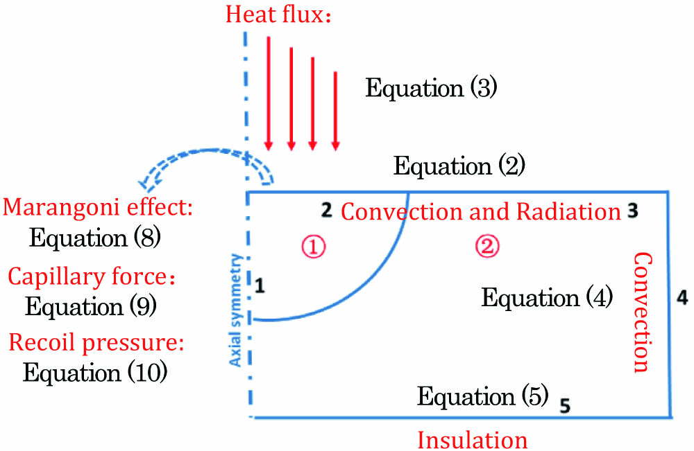
A transient, two-dimensional, axisymmetric model based on the finite element method is developed to simulate the process of material heating, melting, and evaporation. In this work, the heat transfer model is used to compute the temperature. Phase change kinetics is employed to track the solid-melt interface. The fluid flow model coupled with the heat transfer model is utilized to calculate the flow velocity of the melt pool. The deformed geometry interface is applied to predict the surface profile of laser ablation. The computational model is presented in Fig. 1. The governing equations and boundary conditions are labeled in Table 1.
The transient temperature field is solved in the classical convection/diffusion function, expressed by Eq. (1) in Table 1. During laser ablation, the material undergoes phase change, the latent heat consumed or released during the phase transition is considered, and the heat change certainly influences the surface temperature, recoil pressure, and fluid velocity. Therefore, the temperature dependent properties of fused silica, such as the heat conductivity coefficient[19], specific heat capacity[20], and dynamic viscosity[10] are incorporated in the computational model, as shown in Fig. 2. Other material properties and laser ablation parameters used in this work are shown in Table 2. The incident laser energy is loaded as a Gaussian distribution surface heat flux in Eq. (3). The energy is absorbed into silica glass, and the heat dissipates by conduction. It is, however, not the only mechanism of heat loss. The heat is also lost through radiative and nature convection on the solid-air interface, as the shown boundary conditions of Eqs. (2), (3), and (4) in Fig. 1.
Parameter (units)
Nomenclature
Value
Melting temperature (K)
Tm
1875[19]
Vaporization temperature (K)
Tv
2500[23]
Latent heat of evaporation (MJ/kg)
Lv
11.4[18]
Absorptivity
A
0.8[18]
Initial temperature (K)
T0
298.15
Density (kg/m3)
ρ
2201[23]
Radiation emissivity
ε
0.8[23]
Stefan Bolzmann constant [W/(m2·K4)]
σ
5.67×10⁻⁸
Universal gas constant [J/(mol·K)]
R
8.314
Surface tension coefficient (N/m)
γ
0.38
Temperature derivative of surface [N/(m·K)]
əγ/əT
−6×10⁻⁵
Pressure (Pa)
P0
105
Table 2. Material Properties of Fused Silica and Laser Ablation Parameters
Figure 2.Temperature dependent material properties of fused silica. (a) Specific heat capacity and heat conductivity coefficient, (b) dynamic viscosity.
Then, fluid flow coupled with heat transfer and phase change kinetics is modeled. The fluid flow field is governed by the Navier–Stokes equations in Table 1, Eqs. (6) and (7). Marangoni convention, capillary force, and recoil pressure are employed in the fluid field. Capillary force is implemented with a weak constrain term[21], acting in the normal direction of the laminar flow interface. The Marangoni effect is applied by the multi-physics interface, acting in a tangential direction. Recoil pressure is exerted using an open boundary condition[22]. The recoil pressure acts inside the irradiated area with the spatial distribution of laser intensity. Only in the region where temperature has reached vaporization point is vaporization recoil pressure effective.
Then, to simulate the deformation of the free surface and predict the profile of laser ablation, deformed geometry interfaces are applied. In this method, the displacement of the interface is decided by fluid dynamics. The move velocities of the free surface of boundaries 2 and 3 are used to compute the velocities from the thermal-fluid-coupled multi-physical model.
When a pulse of energy strikes the surface of fused silica, the laser energy is absorbed in a thin surface layer due to the high absorptivity of fused silica at the wavelength of 10.6 μm. The temperature rises quickly. The spatial distribution and temporal evolution of the temperature are not taken into account in this work, which can be observed in previous work[17].
In the multi-physical thermal-fluid-coupled model, at the initial stage of laser interaction, only melting occurs. The dynamic viscosity exponential decreases with temperature. The temperature gradient caused Marangoni convention and the gravitational force dictate the melt flow, tending to extend material outwards. As shown in Fig. 3(a), however, it is insufficient to affect the surface profile. As the laser continues to irradiate, the surface temperature reaches the vaporization temperature. Recoil pressure acts on the surface, resulting in the molten fused silica flowing outward of the molten pool, as shown in Fig. 3(b). Compared to the initial stage, the velocity and pressure of this stage increase quickly, as can be obviously observed in Table 3. Soon, the vaporization recoil pressure dominates the fluid field, and the velocity sustained rapid increases. The outward flow eventually forms a keyhole [Fig. 3(c)]. The dynamic viscosity increases rapidly along the center to the edge of the molten pool due to the temperature decreasing in the radial direction. A hump of molten material accumulated at the surface, where the velocity of the flowing material cannot keep up with the speed of the outward flow. Figure 3(c) shows the deep crater and pileup of the surface at the end of the laser pulse.
Time (μs)
Maximum Velocity (m/s)
Maximum Pressure (Pa)
Maximum Temperature (K)
25.0
4.98×10⁻⁹
4.8×10⁶
2.01×10³
35.5
5.42×10⁻³
15×106
2.50×10³
40.0
0.074
523×106
2.55×10³
40.5
5.18×10⁻⁶
5.5×10⁶
2.05×10³
Table 3. The Detected Maximum Velocity, Pressure, and Surface Temperature of the Fluid Field at Different Timesa
Figure 3.Phase distribution, special velocity field, and surface profile at (a) 25 μs, (b) 35.5 μs, (c) 40 μs, and (d) 40.5 μs with laser intensity and pulse duration .
After the laser pulse turns off, the recoil pressure steep descents. At this stage, the capillary force (surface tension due to the deformed surface tends to flat), the Marangoni convention, and gravity command the movement of the melt pool. The molten fused silica tends to retract to the original surface. As can be seen in Fig. 3(d), the velocity is towards the center of the ablated crater. Compared to the initial stage, as shown in Table 3, the velocity of this stage is higher due to the contribution of capillary force. However, due to the high cooling rate and high viscosity, it is also insufficient to observably affect the surface profile. The resolidification surface morphology is the same as the moment of laser shutdown.
The vaporization recoil pressure is the key factor dominating the final surface topography of laser ablation. It determines the ablation depth, crater diameter, and pileup height of high precision laser ablation and laser beam figuring. In addition, the recoil pressure strongly depends on average laser energy density and laser pulse duration, as Eq. (10) indicates. Therefore, numerous models are computed to analyse the influence of laser pulse duration and laser energy on laser ablation.
Figure 4(a) illustrates that the curves of axial ablation depth change with the laser pulse durations. For pulse duration with laser power and with laser power , the ablation depth increases exponentially with the laser pulse duration, as the simulated results have a good fit by using the exponential function. While, for the keyhole start to form at to an interaction time of with laser power , the ablation depths are not consistent with exponential growth. Due to the absorbed energy not being enough to evaporate the material homogenously in this range, it does not reach the steady evaporation state[18]. Similar results can also been seen for laser power of .
Figure 4.(a) Axial ablation depth depending on laser pulse duration with laser intensity of and . (b) Axial ablation depth depending on laser power with laser pulse duration of 34 μs and 30 μs. (c) The ablation radius and pile-up height dependent on ablation depth.
Figure 4(b) shows the curves of axial ablation depth changes with the laser intensity. A linear increase of ablation depth with the laser intensity after exceeding the unsteady vaporization is acquired. It can also be observed that the increase rate of longer pulse duration of 34 μs is faster, compared to the shorter duration of 30 μs.
Figure 4(c) illustrates the increase of the ablation radius and pileup height with the ablation depth. It indicates that the depth and the width of the ablation crater increase with laser energy or pulse duration. The height of the piled-up material increases linearly with the ablation depth. However, the piled-up material influences the subsequent laser strike on the material and forms a bumpy surface, which directly damages the surface roughness. Therefore, a higher ablation depth would result in the rougher manufactured surface.
Verification experiments and laser beam figuring experiments are carried out. The samples used are flat fused silica components with a diameter of 30 mm and thickness of 3 mm. The samples are cleaned in a weak base and ultrasonic water before the laser irradiation. The average surface roughness of the initial surface is around 0.5 nm (measured by a white light interferometer with a measured area of ).
The experimental setup is shown schematically in Fig. 5. Experiments are carried out by using a laser with a wavelength of 10.6 μm and a maximum average power output of 10 W. The pulse duration and frequency are adjustable within a range of 1 to 40 μs and 1.25 to 25 kHz, respectively. The laser beam scans on the sample surface by a co-axial scanning galvanometer with a ZnSe lens with a focal length of 100 mm. The focused beam diameter is about 100 μm with Gaussian distribution intensity. The scanning mode used is one direction scanning (solid arrow) with an empty return trip (dotted arrow), as shown in Fig. 5.
Figure 5.Experimental setup (left) and scanning method (right).
Surface morphology and surface roughness of the samples are examined by a zygo white light interferometer (model: SER4237A-1). The local area ablation uses 1 × magnification with a measured area of and a roughness measurement by using 10 × magnification with a measured area of .
To validate the computation model, single pulse ablation experiments are carried out on the surface with different laser powers. The repetition rate and the scan speed are set as 1.25 kHz and , respectively, to ensure the ablation spots no overlap. Experimental results are demonstrated in Fig. 6. For laser power higher than , the single pulse ablation depth increases linearly with laser intensity. For laser intensity less than , the ablation depth is different from the linear increase. The experimental results are in very good agreement with law of the model predicted. Because the pulse mode simulated in the numerical model is a rectangular pulse, but the pulse mode in the experiment is a Q-switched pulse, it is reasonable that the experiment energy intensity is lower than the computational laser intensity for the same ablation depth. With laser intensity of , the nanometer ablation depths of are achieved, which proves a pulse laser can meet the demands of laser beam figuring.
Figure 6.Single pulse ablation depths as a function of laser intensity.
Homogenous ablation can be obtained by controlling the ablation overlap rate . The overlap rate not only affects the homogeneousness of laser figuring, but also influences surface roughness and processing efficiency, which is determined by scan speed, frequency, and laser diameter:
Laser beam figuring requires acquiring homogenous ablation and not damaging the initial roughness. To investigate the influence of the overlap rate, the local area of homogenous ablation experiments are carried out. The laser power stays constant at , and the repetition rate keeps . The overlap rate varies from 10% to 90%, which is controlled by adjusting the scan speed from 12.5 to .
For the overlap rate less of than 40%, a single ablation crater can be seen, as shown in Fig. 7(a). With the increase of the overlap rate, homogenous ablation is obtained in Fig. 7(b). As the overlap rate becomes too high, roughness increases rapidly, as shown in Fig. 7(c). The rms of the overlap rates from 30% to 60% is lower than 1 nm, as demonstrated in Fig. 7(d), which indicates that laser beam figuring would not significantly damage the initial roughness under appropriate overlap rates. It is the result from multiple laser pulses ablating the same area due to the high overlap rate and gasification material redeposits on the surface. Therefore, in laser beam figuring, a suitable overlap rate should be selected. In addition, a nearly exponential increase of local ablation depth with the overlap rate is observed, as illustrated in Fig. 7(d).
Figure 7.Profiler images of ablated areas with varied overlap rates of (a) 25%, (b) 50%, and (c) 70%. (d) Ablation depths and roughness rms of ablated area as a function of the overlap rates with and .
Laser beam figuring should be capable of selectively homogenous ablation with various ablation depths. Based on single pulse laser ablation and overlap rate local area ablation studies, the influence of laser intensity on local homogenous ablation is studied. The overlap rate stays at 60%. Various nanometer local homogenous ablation depends on laser intensity, as shown in Fig. 8. Experimental results demonstrate that the ablation depth increases nearly linearly with the laser intensity, as shown in Fig. 8(d). For laser intensity of , the ablation depth of 4 nm is obtained. However, the ablation depth fluctuates more significantly with the stability of laser power, compared to single pulse laser ablation, and, due to this reason, the unstable evaporation in local area ablation is not obvious. In Fig. 8(d), it can also be observed that higher ablation depth results in higher surface roughness. In this study, for laser ablation depths , the roughness is less than 1 nm, which does not significantly damage the initial roughness.
Figure 8.Profiler images of ablated areas with laser energy density of (a) , (b) , and (c) . (d) Ablation depth and roughness rms of ablated area as a function of laser intensity with overlap rate of and .
In conclusion, To understand the multi-physical process of pulse laser ablating fused silica, a computational model was proposed in this Letter. The ablation processes of laser surface melting, evaporation, and resolidification of the melt pool were taken into consideration to provide a realistic transient evolution process of melt pool and surface morphology. The vaporization recoil pressure was the dominant factor for determining the final surface topography. By computing numerous ablation models with different pulse durations and laser energies, the ablation depth turned out to linearly increase with laser intensity and exponentially increase with laser pulse duration after homogenous laser ablation. Experimental results of single pulse ablation show strong agreement with the numerical prediction. Further, to obtain homogenous high precision ablation with good surface roughness for laser figuring, a suitable overlap rate should be chosen. For local homogenous ablation, down to 4 nm depth homogenous local ablation was obtained.
Ting He, Chaoyang Wei, Zhigang Jiang, Zhen Yu, Zhen Cao, Jianda Shao. Numerical model and experimental demonstration of high precision ablation of pulse CO2 laser[J]. Chinese Optics Letters, 2018, 16(4): 041401