
Yulong Cui, Xin Tian, Binyu Rao, Hao Li, Wei Huang, Wenxi Pei, Meng Wang, Zilun Chen, Zefeng Wang. A 110 W fiber gas Raman laser at 1153 nm[J]. High Power Laser Science and Engineering, 2023, 11(1): 01000e10
- High Power Laser Science and Engineering
- Vol. 11, Issue 1, 01000e10 (2023)
Abstract
1 Introduction
Stimulated Raman scattering (SRS) is a common and effective method to realize wavelength conversion beyond the wavelength obtained by conventional methods. As SRS in gas materials was first reported in 1963[1], it has been regarded as a promising method to realize a narrow-linewidth and tunable laser source. However, it requires a high pump power to exceed the Raman threshold. One possible method is to increase the effective length of the system, which will reduce the Raman threshold. Hollow-core fiber (HCF) is a new kind of fiber that has a hollow-core structure and can be filled with different gases in the core region[2–4]. It combines both the narrow-linewidth characteristic of the Raman scattering in gases and good beam quality characteristics of fiber Raman lasers. It not only increases the interaction length between the laser and the gas, but also confines the light into the hundred μm2 core mode field area, which provides an ideal environment for the gas SRS. Thus, the Raman threshold is reduced by several orders of magnitude from megawatts to dozens of watts.
Since the first fiber gas Raman laser (FGRL) was reported in 2002[5], there have been many reports about FGRLs in the past 20 years. The output wavelength ranged from the near-infrared[6–13] to the mid-infrared[14–20] and the longest wavelength is above 4.4 μm[14,18]; however, the output power was almost at the watt level. In 2007, the first continuous wave (CW) pumped FGRLs based on a hollow-core photonic crystal fiber (HC-PCF) were reported. In a single-pass configuration, over 8.5 W CW 1064 nm pump power coupled into 30 m PCF filled with 5 bar H2 and 1135 nm Raman laser was obtained. The threshold is only 2.25 W and over 99% of the pump power is converted to Raman power. When using fiber Bragg gratings (FBGs) in the system, which contains a cavity, the threshold was reduced below 600 mW[6]. In 2010, Couny et al.[7] reported 55 W high-power FGRLs at 1131 nm pumped by a 92 W fiber laser with linewidth less than 100 kHz at 1061 nm using H2 as the Raman gas. However, the input end of the HC-PCF used above was ‘open-end’, which may be limited by the coupling efficiency and the maximum input power. Other high-power lasers around 1150 nm are mostly realized by Raman fiber lasers. In 2009, a more than 150 W spectrally clean CW Raman fiber laser at 1120 nm with an optical efficiency of 85% was firstly reported[21]. In 2017, a 1.2 kW clad pumped Raman all-passive-fiber laser at 1120 nm was reported[22]. In 2019, a 919 W random laser at 1150 nm was reported[23]. Compared with the high-power Raman fiber lasers above, although there is still a certain gap in output power, FGRLs have a narrower linewidth of the output and a shorter fiber length is needed. The transmission band of the HCF is easily controlled and is more conductive to suppress the generation of high-order Stokes power.
In this paper, we demonstrate a 110 W CW fiber gas laser at 1153 nm in H2-filled HC-PCF. A homemade narrow-linewidth fiber oscillator with 0.15 nm 3 dB linewidth at the maximum output power of 380 W is used as the pump source. An HCF end-cap is used as the input end to couple several hundred watts of pump power into the core of the HC-PCF and seal the gas cavity. Pumped by this fiber oscillator, a hundred-watt-level FGRL using H2-filled HC-PCF is realized. When filling the 5 m long HC-PCF with around 36 bar H2, around 110 W CW first Stokes power at 1153 nm was obtained with the conversion efficiency of 48.9%, which is the highest CW Stokes power in FGRLs.
Sign up for High Power Laser Science and Engineering TOC. Get the latest issue of High Power Laser Science and Engineering delivered right to you!Sign up now
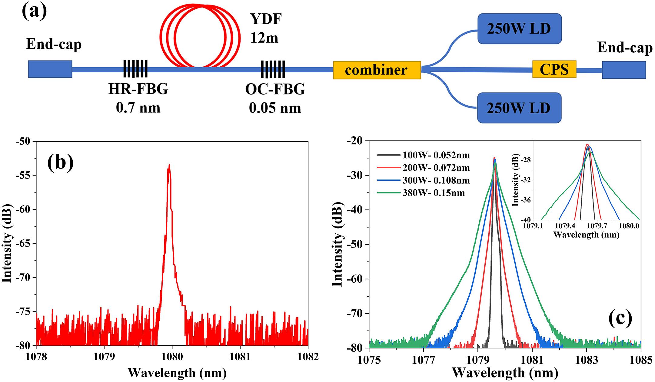
Figure 1.(a) Schematic diagram of the narrow-linewidth fiber oscillator. (b) Measured spectrum of the OC-FBG. (c) Spectrum of the output. Inset: fine spectrum around the central wavelength.
2 Experimental setup
2.1 Narrow-linewidth fiber oscillator
The laser source used in this experiment is a homemade narrow-linewidth fiber oscillator, as shown in Figure 1(a). A 12 m long Yb3+-doped fiber (20/400 μm) with two FBGs is used as the cavity. The full width at half maximum (FWHM) of the high reflectivity (HR)-FBG is 0.7 nm and the FWHM of the output coupled (OC)-FBG is 0.05 nm; the measured spectrum of the OC-FBG is shown in Figure 1(b). Two laser diodes (LDs) operating at 976 nm are used as the pump with a backward pump structure using a (2 + 1) × 1 coupler. A cladding pump stripper (CPS) is used to filter the residual cladding pump power. The forward and backward output ends are spliced with end-caps to prevent the backward light and protect the end. The maximum output power of the oscillator can reach 380 W, with efficiency of about 83%. The spectrum of the fiber oscillator is measured using a single-mode fiber and the result is shown in Figure 1(b). The 3 dB linewidth of the fiber oscillator at different powers is shown in the figure; at the maximum power of 380 W, the 3 dB linewidth is about 0.15 nm. So far, the highest power spectral density reported is 5.7 W/pm by an all-fiber FBG-based laser oscillator[24]; the power spectral density of our fiber oscillator is 2.53 W/pm at the 380 W power level, which is also very high.
![]()
Figure 2.(a) Experimental setup of the H2-filled FGRL. L: lens; R: reflector; PM: power meter; OSA: optical spectrum analyzer. Inset: thermal image of the input end of HC-PCF. (b) HCF end-cap. (c) Measured loss of the HC-PCF. Inset: cross-section of the HC-PCF.
2.2 Details of the system
The experimental setup of the H2-filled FGRL is shown in Figure 2(a). The core diameter of the output fiber of the narrow-linewidth fiber oscillator mentioned in Figure 1 is 20 μm. The HC-PCF we used in this experiment is HC-1060-02 from NKT Photonics with the core diameter of 10 μm, as shown in the inset picture of Figure 2(c), and the mode field diameter (MFD) is around 7.5 μm. The cutting off method is used to measure the fiber loss and the measured fiber loss of the HC-PCF is shown in Figure 2(c); at the wavelength of the pump of 1080 nm, the measured fiber loss is 0.056 dB/m, for the first-order Stokes wavelength of 1153 nm, the measured fiber loss is 0.06 dB/m, and for the second-order Stokes wavelength of 1236 nm, the measured fiber loss is 0.45 dB/m. Because the MFD of the narrow-linewidth fiber oscillator is larger than that of the HC-PCF, to realize the mode field matching, four plano-convex lenses are used with the focal lengths of 30, 30, 75 and 30 mm. All the lenses are fixed on the three-axis adjustment stage. According to the Gaussian beam transformation through the lenses, the MFD should be changed to around 7.5 μm. Although the MFD of the laser after transmission through the lenses is similar to the MFD of the HC-PCF, the coupling efficiency is only around 59%, which may cause a great deal of heat to accumulate at the input end of the HC-PCF. Therefore, the input end of the HC-PCF is fabricated with an end-cap, as shown in Figure 2(b), and is fixed on a water cooled fixture; the thermal image is shown in the inset picture of Figure 2(a). The HCF end-cap can not only help couple several hundred watts of pump power into the HC-PCF, but also seal the gas cavity. The details of the fabrication between the HCF and end-cap can be found in Refs. [25, 26]. The other end is fixed in the gas cell, which can be used to fill the HC-PCF with H2. The transmission window on the gas cell is made by uncoated ultraviolet fused silica and the transmission is around 90% from 1000 to 1300 nm. After the pump laser transmits through high-pressure H2 in the HC-PCF, the pump laser will be transferred into the first-order Stokes and the second-order Stokes power. The output laser is first collimated by a plano-convex lens with focal length of 30 mm and then the output laser is split into two parts. Around 92% of the output laser transmits through the wedge mirror and is measured by PM1 (power meter), and the other 8% of the output laser reflex by the wedge mirror is measured by PM2. Two long wave pass filters (LPFs) fixed on flip mounts are used at the reflective side. The minimum transmission wavelength of one LPF is 1100 nm, and it is used to measure the total Stokes power; it has around 88% transmission at 1153 nm. The minimum transmission wavelength of the other LPF is 1200 nm, and it is used to measure the second-order Stokes power; it has around 89% transmission at 1237 nm. A multimode fiber is used to collect the scattered light of PM1 to measure the spectrum of the output laser.
![]()
Figure 3.(a) Measured spectrum of the output laser at different pump powers when the fiber length is 5 m with the H2 pressure of 30 bar. (b) Measured spectrum of the output laser at different H2 pressures when the fiber length is 5 m with the maximum pump power. Inset: fine spectra of the pump, first-order Stokes laser and second-order Stokes laser. 3 dB linewidth of the output laser at (c) different pump powers and (d) different gas pressures.
3 Results and discussion
3.1 Output spectrum
The output spectrum is shown in Figure 3. Apart from the pump wavelength of 1079.6 nm, two Stokes lines are observed: one is the first-order Stokes line of 1152.6 nm converted from the pump (rotational Raman frequency of 587 cm–1), whereas the other is the second-order Stokes line of 1236.3 nm converted from the first Stokes line (rotational Raman frequency of 587 cm–1). Figure 3(a) shows the spectrum at different pump powers, and the fine spectra are shown in the inset; the 3 dB linewidth of the output is shown in Figure 3(c). For the same fiber length and gas pressure, as the pump power increases, the linewidths of the residual pump and the first-order Stokes line show an upward trend. The linewidth of the second-order Stokes line is almost the same when the pump power increases. The intensity of the first-order Stokes and second-order Stokes lines is associated with the linewidth of the pump, which will influence the power density. As the pump power increases to a certain extent, the power density decreases instead, and thus the intensity of the second-order Stokes line decreases.
![]()
Figure 4.(a) First-order Stokes power, (b) first-order Stokes efficiency and power spectral density of the pump, (c) second-order Stokes power and (d) residual pump power vary with coupled pump power at different gas pressures with the fiber length of 5 m.
Figure 3(b) shows the spectrum at different H2 pressures; the 3 dB linewidth is shown in Figure 3(d). As the gas pressure increases, the 3 dB linewidths of the residual pump, first-order Stokes line and second-order Stokes line are almost the same. As the gas pressure increases, the threshold of the Stokes lines is reduced, and the power of the pump with a wider spectral range can be converted into the Stokes power; therefore, the total linewidth of the Stokes line becomes wider as the gas pressure increases. From the output spectrum, the linewidth of the first-order Stokes line is narrower than that of the residual pump, which is mainly because of incomplete conversion of the pump; only the part of the pump near the central wavelength is converted to the first-order Stokes power. In some conditions, such as the gas pressure of 30 or 36 bar, the first-order anti-Stokes light of 1015.3 nm converted from the pump (rotational Raman frequency of 587 cm–1) is observed, which is marked by red circles ; this is caused by four-wave mixing (FWM). In addition, the spectrum of the output is measured by multimode fiber, and the 3 dB linewidth in Figures 3(c) and 3(d) is higher than the actual value.
3.2 Power characteristics
Figure 4 shows the power characteristics of the FGRL filled with H2 at the fiber length of 5 m with different gas pressures. The gas pressure of the H2 mainly influences the Raman gain and Raman threshold. Figure 4(a) shows that the first-order Stokes power varies with coupled pump power at different gas pressures. As the gas pressure increased, the threshold of the first-order Stokes power decreased, and the first-order Stokes power is easily produced. The threshold of first-order Stokes power is around 35 W coupled pump power, as shown in the figure. Figure 4(b) shows the first-order Stokes efficiency, which is calculated as first-order Stokes power divided by coupled pump power, and the power spectral density of the pump varies with the coupled pump power. The efficiency of the first-order Stokes power increases first and then decreases with the increasing pump power. This is due to the spectral broadening of the pump, and the power spectral density starts to decrease at high pump power. As the gas pressure increases, the power and efficiency of the first-order Stokes power are also increased, and at the gas pressure of 30 bar, the first-order Stokes power has an obvious increment. According to Figure 4(b), we can infer that the trend of the first-order Stokes efficiency is almost consistent with the trend of the pump spectral density. Figure 4(c) shows that the second-order Stokes power varies with the coupled pump power at different gas pressures. The second-order Stokes power is produced by the first-order Stokes power; therefore, the second-order Stokes power is mainly influenced by the power spectral density of first-order Stokes power, and the power shows a trend of increasing first and then decreasing, which is consistent with the trend of Figure 4(b). Figure 4(d) shows that the residual pump power varies with the coupled pump power. It increases first when there is no Stokes line observed, and then when the pump power starts to transfer to the Stokes power, the residual pump power starts to decrease. With the spectral broadening of the pump, the conversion from the pump power to the Stokes power is weakened, and the residual pump power increases again. As the gas pressure increases, more pump power can be converted to Stokes power. As mentioned in Figure 3(b), when the gas pressure is 30 bar, there is an FWM process, which may promote the conversion from the pump power to the first-order Stokes power; this may be the reason why the Stokes power has a significant increase at the gas pressure of 30 bar.
According to the results in Figure 4, the gas pressure of H2 is further increased to 36 bar, and the result is shown in Figure 5. Compared with the results in Figure 4, the first-order Stokes and second-order Stokes powers both show an increment and there is less pump power remaining. The maximum output power of first-order Stokes power is 110 W, and the conversion efficiency of the first-order Stokes power is around 48.9%, which is the ratio of the first-order Stokes power to the coupled pump power. As the gas pressure increases from 30 to 36 bar, the first-order Stokes power is nearly the same as that of 30 bar gas pressure; however, the second-order Stokes power of 36 bar is almost twice that of 30 bar gas pressure. The increment of the gas pressure will further reduce the threshold of second-order Stokes power, which is unwanted here. The output beam profile is shown in the inset figure of Figure 5. It is measured through the reflected part of the wedge mirror; as an LPF1100 is used, the residual pump is filtered and only Stokes power remains. Because second-order Stokes power is much smaller than first-order Stokes power, the influence of second-order Stokes power is ignored, and the pure Stokes power still retains a good beam profile.
![]()
Figure 5.First-order Stokes power, second-order Stokes power and residual pump power vary with coupled pump power at 36 bar H2 pressure with the fiber length of 5 m. Inset: beam profile of the Stokes laser.
![]()
Figure 6.(a) Experimental and simulated results of the Stokes and residual pump powers varying with the coupled pump power. The dotted lines represent the simulated results and the scatters represent the measured results. (b) Simulated first-order Stokes power varying with the coupled pump power at different fiber lengths.
3.3 Numerical model
Subsequently, we established a numerical model of the FGRL, which considers the process of the rotational Raman frequency concluding first-order Stokes and second-order Stokes power. Compared with the numerical model in Ref. [27], we considered the influence of the pump linewidth. Through decomposing the pump into several segments, each segment is calculated as a single wavelength model and the total power is the summation of all the segments. The dotted lines in Figure 6(a) show the simulated power; compared with the measured results, as the scatters show, the trends of the Stokes power and the residual pump power are consistent when the coupled pump power is below 150 W. In addition, for the simulated second-order Stokes power, there is the same trend of increasing first and then decreasing with the measured power, which is mainly influenced by the power density of the pump. However, the simulated first-order Stokes power and residual pump power have a certain difference from the measured results, as the coupled pump power is over 150 W. This may be because the FWM is not considered in our numerical model, but it was obtained in the experiment. The existence of FWM may promote the pump power converting to the first-order Stokes power. Figure 6(b) shows the simulated results at different fiber lengths; as the fiber length is longer than 5 m, there is a great deal of second-order Stokes power generation and, therefore, as the coupled pump power is between 50 and 200 W, the output first-order Stokes power when the fiber length is 8 and 10 m is less than that when the fiber length is 5 m. Although from the simulated results, the output power of first-order Stokes power with the fiber length of 8 m is nearly the same as that of 5 m fiber length, we still choose the 5 m length to avoid getting too much second-order Stokes power. Too short a fiber length will increase the threshold of first-order Stokes power, and the output power of first-order Stokes power is also lower than that of 5 m.
4 Conclusion
In conclusion, we have demonstrated 110 W FGRLs in H2-filled HC-PCF pumped by a homemade narrow-linewidth fiber oscillator based on an HCF end-cap. With the maximum pump power of around 380 W at 1080 nm with the power spectral density of 2.53W/pm, nearly 110 W first-order Stokes power at 1153 nm is obtained with the H2 pressure of 36 bar and 5 m long fiber length, and the conversion efficiency of first-order Stokes power is around 48.9%. Through the HCF end-cap, more pump power can be coupled into the HCF; however, the power spectral density is still lower than that of a single-wavelength fiber laser, so there is still over 60 W pump power remaining. Through the establishment of the numerical model, the simulated results are in good agreement with the experiment without the FWM process. Further narrowing the pump linewidth can improve the conversion efficiency. In addition, the coupling efficiency from the pump into the core of the HC-PCF is only 59%, which can be further optimized. This work paves the way for high-power narrow-linewidth FGRLs.
References
[1] R. W. Minck, R. W. Terhune, W. G. Rado. Appl. Phys. Lett., 3, 181(1963).
[2] R. F. Cregan. Science, 285, 1537(1999).
[3] F. Gérôme, R. Jamier, J. L. Auguste, G. Humbert, J. M. Blondy. Opt. Lett., 35, 1157(2011).
[4] F. Yu, W. J. Wadsworth, J. C. Knight. Opt. Express, 20, 11153(2012).
[5] F. Benabid. Science, 298, 399(2002).
[6] F. Couny, F. Benabid, P. S. Light. Phys. Rev. Lett., 99, 143903(2007).
[7] F. Couny, B. J. Mangan, A. V. Sokolov, F. BenabidLasers and Electro-Optics (CLEO) and Quantum Electronics and Laser Science Conference (QELS). , , , and , in (), paper CTuM3.(2010).
[8] Z. Wang, F. Yu, W. Wadsworth, J. Knight. Laser Phys. Lett., 11, 105807(2014).
[9] Y. Chen, Z. Wang, Z. Li, W. Huang, X. Xi, Q. Lu. Opt. Express, 25, 20944(2017).
[10] Z. Li, W. Huang, Y. Cui, B. Gu, Z. Wang. J. Light. Technol., 36, 3700(2018).
[11] Z. Li, W. Huang, Y. Cui, Z. Wang, W. Wu. Opt. Express, 26, 12522(2018).
[12] Z. Li, Z. Zhou, W. Huang, Y. Cui, Z. Wang. Opt. Eng., 57, 56111(2018).
[13] Z. Li, W. Huang, Y. Cui, Z. Wang. Appl. Opt., 57, 3902(2018).
[14] A. V. Gladyshev, A. F. Kosolapov, M. M. Khudyakov, Y. P. Yatsenko, A. N. Kolyadin, A. A. Krylov, A. D. Pryamikov, A. S. Biriukov, M. E. Likhachev, I. A. Bufetov. Quantum Electron., 47, 491(2017).
[15] L. Cao, S. Gao, Z. Peng, X. Wang, P. Wang. Opt. Express, 26, 5609(2018).
[16] Z. Li, W. Huang, Y. Cui, Z. Wang. Opt. Lett., 43, 4671(2018).
[17] A. V. Gladyshev, A. F. Kosolapov, M. M. Khudyakov, Y. Yatsenko, A. N. Kolyadin, A. A. Krylov, A. Pryamikov, A. S. Biriukov, M. E. Likhachev, I. A. Bufetov. IEEE J. Sel. Top. Quantum Electron., 3, 0903008(2018).
[18] M. S. Astapovich, A. V. Gladyshev, M. M. Khudyakov, A. F. Kosolapov, M. E. Likhachev, I. A. Bufetov. IEEE Photon. Technol. Lett., 1, 78(2019).
[19] W. Huang, Y. Cui, Z. Li, Z. Zhou, Z. Wang. Chin. Opt. Lett., 7, 071406(2019).
[20] Y. Wang, M. K. Dasa, A. I. Adamu, J. Antonio-Lopez, C. Markos. Opt. Lett., 45, 1938(2020).
[21] Y. Feng, L. R. Taylor, D. B. Calia. Opt. Express, 17, 23678(2009).
[22] Y. Glick, Y. Shamir, M. Aviel, Y. Sintov, S. Goldring, N. Shafir, S. Pearl. Opt. Lett., 43, 4755(2018).
[23] H. Zhang, L. Huang, J. Song, H. Wu, P. Zhou, X. Wang, J. Wu, J. Xu, Z. Wang, X. Xu, Y. Rao. Opt. Lett., 44, 2613(2019).
[24] Y. Huang, P. Yan, J. Xin, D. Li, Y. Wu, Q. Xiao, L. Zhu, M. Gong. Opt. Fiber Technol., 68, 102774(2022).
[25] Y. Cui, X. Ye, J. Shi, W. Huang, Z. Zhou, M. Wang, Z. Chen, Z. Wang. IEEE Photon. J., 14, 7909806(2022).
[26] Y. Cui, W. Huang, Z. Zhou, H. Li, M. Wang, Z. Chen, Z. Wang. Chin. Opt. Lett, 20, 040602(2022).
[27] W. Pei, H. Li, W. Huang, M. Wang, Z. Wang. Crystals, 11, 711(2021).

Set citation alerts for the article
Please enter your email address
© Copyright 2018-2021 | Chinese Laser Press. All Rights Reserved 沪ICP备15018463号-20