Chongjia Huang and Erwin H. W. Chan*
Abstract
New techniques for controlling the amplitudes of two orthogonal linearly polarized light are presented. One is based on adjusting the DC voltage into a Mach–Zehnder modulator (MZM) to alter the amplitude of the light traveling on the slow axis of a fiber into the modulator with little changes in the fast-axis light amplitude. Another is based on adjusting the input DC voltages of a dual-polarization MZM operating in the reverse direction, which enables independent control of the two input orthogonal linearly polarized light amplitudes. Experimental results demonstrate that more than 30 dB difference in slow- and fast-axis light power can be obtained by controlling an MZM input DC voltage, and over 24 dB independent power adjustment for light traveling on the slow and fast axes into a dual-polarization MZM.Microwave photonics is a combination of radio wave and photonic technologies[1]. Devices based on microwave photonic techniques can have a large operating bandwidth, are immune to electromagnetic interference, and can simultaneously perform multiple functions. They find applications in electronic warfare[2] and telecommunication[3]. Recently, there has been a growing interest in utilizing two orthogonal linearly polarized optical signals, where one travels on the slow axis and the other travels on the fast axis of a fiber, to implement a microwave photonic device[4–8]. The amplitudes of these signals need to be controlled for these devices to realize specific functions. For example, a linearized analog photonic link, presented in Ref. [5], requires the two orthogonal linearly polarized optical signals to have the same amplitude, while these two optical signals need to have different amplitudes in a microwave-photonic-based frequency tripler[8]. Commercial variable optical attenuators and optical amplifiers are designed to minimize polarization-dependent loss, and hence the amplitudes of the slow- and fast-axis light change by almost the same amount after passing through these attenuators and amplifiers. Changing the orientation of a polarization rotator in front of a polarizer can change the amplitudes of the slow- and fast-axis light by different amounts, but they cannot be changed independently; i.e., as the polarization rotator angle changes, one of the two orthogonal linearly polarized light amplitudes increases while the other decreases. The two orthogonal linearly polarized light amplitudes can be controlled independently by inserting two variable optical attenuators between a polarization beam splitter (PBS) and a polarization beam combiner (PBC). However, the fiber lengths on the two paths between the PBS and the PBC cannot be exactly matched, which causes the coherent interference problem[9] if the two orthogonal linearly polarized signals are combined coherently in the subsequent stage. Integrating two variable optical attenuators between a PBS and a PBC on the same substrate can solve the coherent interference problem, but such a device is not commercially available. The aim of this Letter is to present two techniques that use off-the-shelf components to provide independent control of the amplitudes of the light traveling on the slow- and fast-axis of a fiber.
Electro-optic Mach–Zehnder modulators (MZMs) are widely used in optical communication systems to convert an electrical signal into an optical domain suitable for transmission. The light traveling into an MZM needs to be aligned to the extraordinary axis of the crystal to obtain the strongest electro-optic interaction to maximize the modulation efficiency. The cross-polarized light entering an MZM interacts via a different and much weaker electro-optic interaction. In order to avoid the cross talk due to the cross-polarized light, commercial MZMs are intentionally designed to have a higher loss for the cross-polarized light. The polarization dependent property of an MZM enables it to be used as a polarization-dependent variable optical attenuator to alter only one of the two input orthogonal linearly polarized light amplitudes via controlling the input DC voltage.
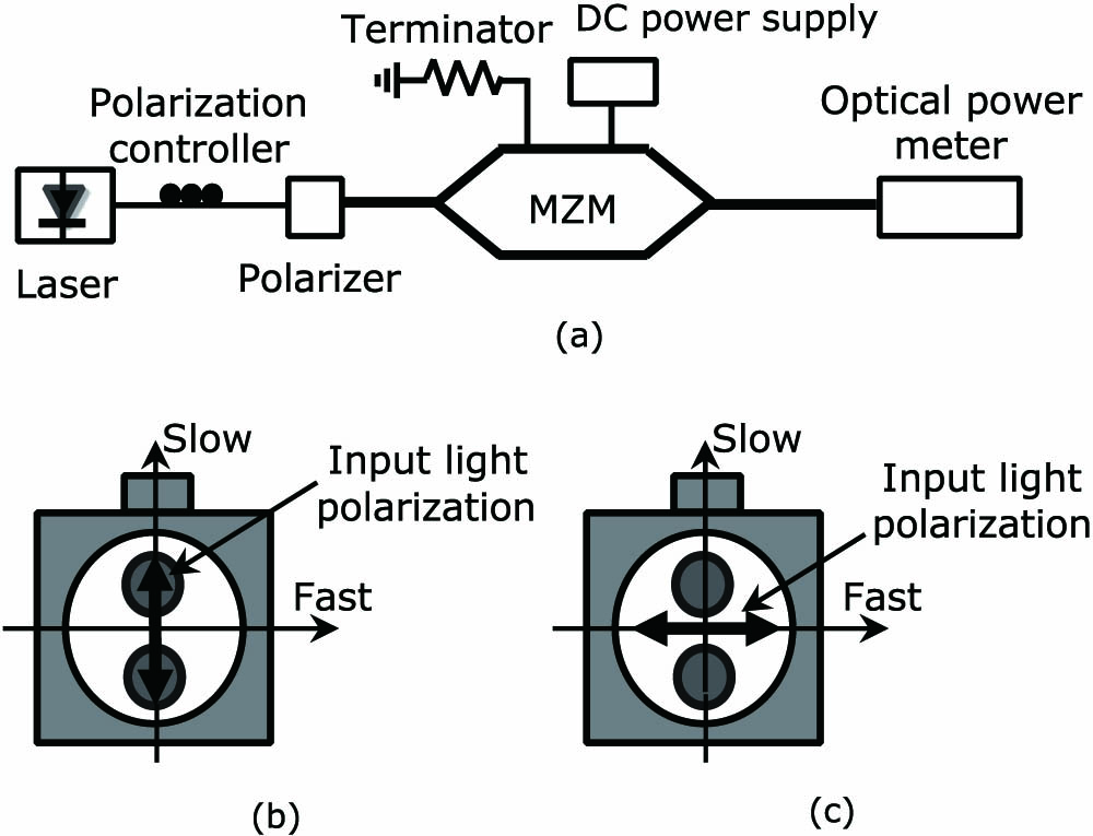
An experiment has been set up, as shown in Fig. 1(a), to obtain the transmission of the slow- and fast-axis light through a commercial MZM for different input DC voltages. The optical source was a wavelength-tunable laser operating at 1550 nm. The polarization controller after the laser was used to align the light polarization state into a polarizer, which blocked the light traveling on the fast axis of a fiber. The light after the polarizer was traveling on the slow axis of a polarization-maintaining fiber (PMF), as shown in Fig. 1(b), into an MZM (EOSpace AX-0MSS-20-LV). The power of the slow-axis light entering the MZM was 9.4 dBm. This MZM was a zero-chirp x-cut intensity modulator and was designed for the input light aligned on the slow axis. The MZM RF port was terminated by a 50 Ω terminator and its DC port was connected to a DC power supply. The solid line in Fig. 2 shows the attenuation of the slow-axis light as it passes through the MZM for different input DC voltages. It shows that the MZM has a switching voltage of 6.6 V and an insertion loss of 3.1 dB, which agree with the modulator specification. The measurement shows that the slow-axis light attenuation for different modulator input DC voltages behaves like the transfer function of the MZM used in the experiment, which has a sinusoidal shape like all other MZMs.
Sign up for Chinese Optics Letters TOC. Get the latest issue of Chinese Optics Letters delivered right to you!Sign up now

Figure 1.(a) Experimental setup for measuring MZM transfer characteristics with different input light polarization states. The bold lines represent polarization-maintaining components. (b) The polarization state of the light traveling on the slow axis of a PMF into the modulator. (c) The polarization state of the light traveling on the fast axis of a PMF into the modulator.
Figure 2.Slow-axis (solid) and fast-axis (dotted) light attenuation in a Mach–Zehnder modulator for different input DC voltages.
The polarizer in Fig. 1(a), which blocked light traveling on the fast axis, was replaced by a slow-axis blocked polarizer. The polarization controller was adjusted to let the fast-axis light, as shown in Fig. 1(c), pass through the polarizer into the modulator. The amount of attenuation was measured for different input DC voltages and is shown by the dotted line in Fig. 2. The measurement indicates that the fast-axis light that passed through the MZM has an insertion loss of around 22 dB, which is much higher than that of the slow-axis light. The reason for this high insertion loss is that the MZM was designed to operate for the slow-axis light and to have high loss for the fast-axis light, to avoid cross talk. Figure 2 shows there is change in the fast-axis light power, which is very small compared to the 34 dB change in the slow-axis light power for the MZM input DC voltage changing from 3.5 to 10.1 V. This demonstrates that an MZM can provide different amounts of attenuation to the slow- and fast-axis light. The attenuation difference for the two light components ranged from to 18.9 dB, as shown in Fig. 3.
Figure 3.Attenuation difference between the slow-axis and fast-axis light in a Mach–Zehnder modulator for different input DC voltages.
The MZM-based variable optical attenuator was also demonstrated when two orthogonal linearly polarized light entered the modulator at the same time. This was done by replacing the polarizer in Fig. 1(a) by a PBC with a PMF at all its input and output ports. The two PBC input ports were connected to two wavelength-tunable lasers with 1550 and 1552 nm wavelengths via polarization controllers. The light with 1550 and 1552 nm wavelengths, which had the same optical power, was traveling on the slow and fast axis of the PMF into the MZM, respectively. The output of the MZM was observed on an optical spectrum analyzer. Figure 4 shows the MZM output for different DC voltages into the modulator. It can be seen from the figure that, as the modulator input DC voltage changes, there is a large change in the 1550 nm slow-axis light amplitude while the 1552 nm fast-axis light amplitude remains almost the same. This verifies that the MZM-based variable optical attenuator only alters the slow-axis light amplitude. It should be noted that, although a commercial MZM can provide a different amount of attenuation to two orthogonal linearly polarized light components, it cannot control the amplitude of the fast-axis light. A commercial dual-polarization MZM operating in the reverse direction, as shown in Fig. 5, can overcome this limitation.
Figure 4.Output spectrum of the MZM-based variable optical attenuator when two different-wavelength orthogonal linearly polarized light components enter the modulator. The DC voltage into the modulator is (a) 3.5 V and (b) 10.1 V.
Figure 5.Dual-polarization MZM-based variable optical attenuator for independent control of the slow-axis (red arrow) and fast-axis (blue arrow) light amplitudes.
A commercial dual-polarization MZM (Fujitsu FTM7980EDA) consists of a 3 dB coupler, two MZMs, a 90° polarization rotator, and a PBC integrated on a waveguide. In conventional operation, the light traveling on the slow axis of a fiber entering the dual-polarization MZM generates two orthogonal linearly polarized RF modulated optical signals. Here, the dual-polarization MZM is operated in the reverse direction, as shown in Fig. 5. In this case, the PBC in the dual-polarization MZM acts as a PBS, which splits the two orthogonal linearly polarized light components into two paths. The slow-axis light traveling on the top path passes through the top MZM (MZY). The fast-axis light traveling on the bottom path passes through a 90° polarization rotator, which rotates the fast-axis light polarization state by 90° before it enters the bottom MZM (MZX). Hence, the amplitudes of the two orthogonal linearly polarized light components at the dual-polarization MZM input can be controlled independently by adjusting the DC voltages into MZX and MZY. The light components at the output of MZX and MZY traveling on the slow axis are combined coherently at the 3 dB coupler. Since all the components in the dual-polarization MZM are integrated on the same substrate, there is no time delay between the two input orthogonal linearly polarized light components after they pass though the modulator, and hence there is no coherent interference problem. Note that operating the dual-polarization MZM in the reverse direction not only can independently control the input slow- and fast-axis light amplitudes but also can convert the two input orthogonal linearly polarized light components to have the same polarization state, which is required in a microwave photonic frequency multiplier[4] and phase shifter[6].
Experiments were conducted to verify the dual-polarization MZM operating in the reverse direction is able to independently control the slow- and fast-axis light amplitudes. The experimental setup was the same as Fig. 1, except the MZM replaced by a reverse-operated dual-polarization MZM (Fujitsu FTM7980EDA) with polarization-maintaining fibers at the input and output ports. The two modulator input RF ports were terminated by 50 Ω terminators. A slow-axis blocked polarizer was first connected to the dual-polarization MZM input to ensure that the light entering the dual-polarization MZM was traveling on the fast axis of the PMF. The power of the fast-axis light into the modulator was 9.3 dBm. The solid lines in Figs. 6(a) and 6(b) show the amount of attenuation in the input fast-axis light for different DC voltages into MZX and MZY. As expected, the fast-axis light was traveling on the bottom path of the dual-polarization MZM, and hence its power can be varied by adjusting the DC voltage into MZX. It can be seen from the figures that there are 32.5 and 1.8 dB changes in the fast-axis light power by varying the MZX and MZY DC voltage from 0 to 8.8 V, respectively. The slow-axis blocked polarizer in the setup was then replaced by a fast-axis blocked polarizer. In this case, the slow-axis light with 9.2 dBm optical power was launched into the dual-polarization MZM. The amount of attenuation in the slow-axis light was measured for different DC voltages into MZX and MZY, as shown by the dashed lines in Figs. 6(a) and 6(b). Since the input slow-axis light was traveling on the top path of the dual-polarization MZM, 24.1 dB change in the slow-axis light power can be obtained by changing the MZY DC voltage from 0 to 6.8 V. There is change in the slow-axis light power for 6.8 V change in the MZX DC voltage.
Figure 6.Attenuation of the input fast-axis (solid) and slow-axis (dash) light for different DC voltages into (a) MZX and (b) MZY.
Experimental results show the two MZM-based variable optical attenuators have a stable performance. However, for long-term operation, and especially when the attenuators are operating over changing temperature conditions, a modulator bias controller is required to avoid the bias drift problem where the modulator transfer function gradually shifts over time, which alters the amount of attenuation provided by the proposed structures. Modulator bias controllers are commercially available. They can be designed to lock the modulator to any point in the transfer function, and are suitable for use in the MZM-based variable optical attenuators. The two MZM-based variable optical attenuators for controlling two orthogonal linearly polarized light amplitudes have the similar complexity to the attenuator based on integrating two variable optical attenuators between a PBS and a PBC. In fact, the variable optical attenuator based on a single MZM is simpler than the latter case. In terms of the cost, since two variable optical attenuators integrated with a PBS and a PBC on the same substrate are not a standard commercial product, they need to be custom made. This requires expensive nonrecurring engineering costs. On the other hand, the attenuators based on a single MZM or an integrated dual-polarization MZM operating in the reverse direction provide a simple off-the-shelf solution for controlling two orthogonal linearly polarized light amplitudes. It was pointed out in Ref. [10] that the modulator DC bias voltage can be applied to the modulator RF port rather than the DC port. This has the advantage of enabling the MZM-based variable optical attenuators to have an ultrafast response time of as the modulator RF port can have a wide bandwidth of . Applying the DC voltage to the modulator RF port can also reduce the MZM-based variable optical attenuator drive voltage to for realizing changes in light amplitude.
In conclusion, two new techniques to control the amplitude of two orthogonal linearly polarized light components have been presented. Adjusting the input DC voltage of an MZM can alter the slow-axis light amplitude with little change in the amplitude of the light traveling on the fast axis of a fiber. Operating a dual-polarization MZM in the reverse direction enables the amplitudes of the slow- and fast-axis light to be controlled independently via the two MZM input DC voltages. Experimental results have been presented that demonstrate and change in the slow- and fast-axis light power, respectively, for 6.6 V change in the DC voltage into an MZM, and independent control of the slow- and fast-axis light power can be obtained by altering the DC voltages into a reverse-operated dual-polarization MZM.
References
[1] T. Nagatsuma, Y. Kado. PIERS Online, 4, 376(2008).
[2] J. Y. Choe. International Topical Meeting on Microwave Photonics, 307(2005).
[3] J. Capmany, D. Novak. Nat. Photon., 1, 319(2007).
[4] Y. Gao, A. Wen, W. Jiang, D. Liang, W. Liu, S. Xiang. IEEE Photonics Technol. Lett., 27, 2260(2015).
[5] Z. Dan, J. Chen, S. Pan. Opt. Express, 24, 11009(2016).
[6] X. Wang, J. Zhang, E. H. W. Chan, X. Feng, B. Guan. Opt. Express, 25, 2883(2017).
[7] T. Li, E. H. W. Chan, X. Wang, X. Feng, B. Guan. IEEE Photon. J., 8, 5501008(2016).
[8] C. Huang, H. Chen, E. H. W. Chan. IEEE Photon. J., 9, 7204010(2017).
[9] E. H. W. Chan, R. A. Minasian. Opt. Commun., 254, 104(2005).
[10] T. Li, E. H. W. Chan, X. Wang, X. Feng, B. Guan, J. Yao. IEEE Photon. J., 10, 5500112(2018).