
D. Shokov, M. Murakami, J. J. Honrubia, "Laser scaling for generation of megatesla magnetic fields by microtube implosions," High Power Laser Sci. Eng. 9, 04000e56 (2021)
- High Power Laser Science and Engineering
- Vol. 9, Issue 4, 04000e56 (2021)
Abstract
1 Introduction
Magnetic fields are applied in various areas of modern physics and engineering. In the past 50 years, researchers have strived to realize strong magnetic fields in laboratories for fundamental studies and diverse applications[1–9]. Approaches include high explosives[10,11], electromagnetic implosions[12,13], high-power lasers[14–19] and Z pinches[20,21]. The principal physical mechanism of these methods is based on magnetic flux compression (MFC)[10] using hollow cylindrical structures and pre-seeded magnetic fields. To date, the highest magnetic field experimentally observed remains of the kilotesla (kT) order[22–24].
Recently, a novel concept called a microtube implosion (MTI)[25] has been proposed. MTI utilizes a structured target and intense laser pulses. Particle simulations have demonstrated that MTI can generate ultrahigh magnetic fields of the megatesla (MT) order. This increase is three orders of magnitude higher than any experimental data. Although MTI uses a similar physical configuration as MFC, it differs from MFC because the ultrahigh magnetic fields in MTI are generated by the spin currents induced by collective Larmor gyromotions.
Irradiating a micrometer-sized, cylindrically hollow target with relativistically intense laser pulses generates hot electrons (Figure 1). These laser-produced relativistic electrons launch a cylindrically symmetric implosion of the inner wall ions toward the central axis. The kilotesla-order, uniform, pre-seeded magnetic fields[22,26–31] parallel to the target central axis launch Larmor gyromotions of electrons and ions, deflecting their trajectories in the opposite direction. Near the target center, currents running on the envelope curves due to the deflected ions and electrons (referred to as Larmor holes[25]) form a strong spin current. Consequently, ultrahigh magnetic fields are generated in a collective manner, amplifying the original seed magnetic field by two to three orders of magnitude. Note, if the cylindrical cavity is replaced by a spherical one, based on another physical concept referred to as microbubble implosion[32–35], ultrahigh electric fields may be obtained close to the Shwinger limit[36] instead of an ultrahigh magnetic field.
Sign up for High Power Laser Science and Engineering TOC. Get the latest issue of High Power Laser Science and Engineering delivered right to you!Sign up now
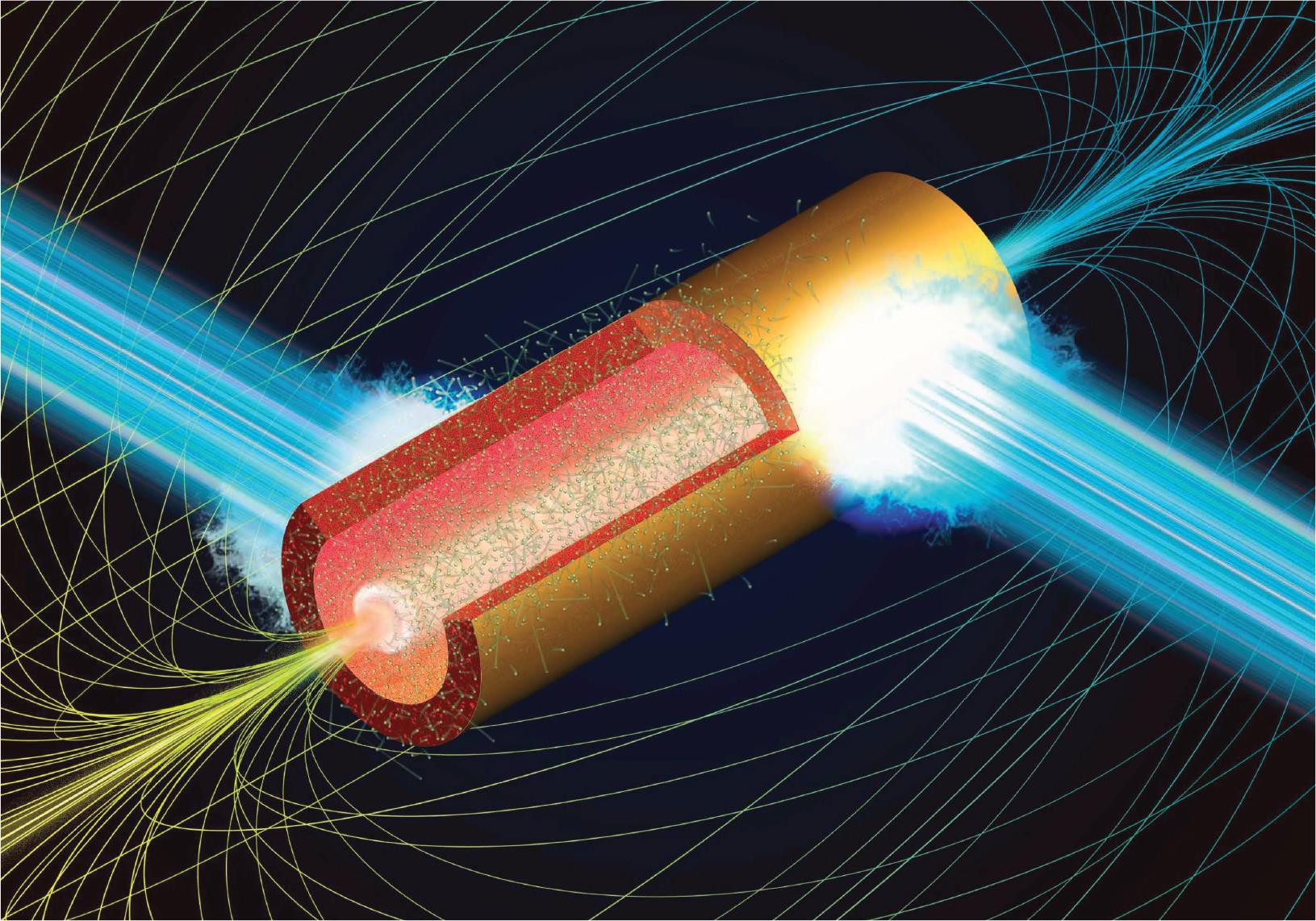
Figure 1.Illustration of a microtube implosion. Due to the laser-produced hot electrons with megaelectron volt energies, cold ions in the inner wall surface implode toward the central axis. By pre-seeding uniform magnetic fields of the kilotesla order, the Lorentz force induces a Larmor gyromotion of the imploding ions and electrons. Due to the resultant collective motion of relativistic charged particles around the central axis, strong spin currents of approximately peta-ampere/cm are produced with a few tens of nm size, generating megatesla-order magnetic fields.
Previously, we proposed the principle of MTI and used two-dimensional (2D) particle-in-cell (PIC) simulations to demonstrate its characteristic behavior in terms of plasma parameters, such as the plasma density, the current and the temperature of the electrons[25]. In this work, we clarify the achievable maximum magnetic fields as a function of external parameters, including the applied laser intensity, laser energy and target structure. This study provides indispensable information to conduct real experiments in a laboratory setting.
Previous studies have discussed a surprising phenomenon called polarity switching[25,37]. Polarity switching causes a plasma-current-driven magnetic field of the order of 0.1–1 MT to initially grow on the central axis in the direction opposite to the seed magnetic field (antiparallel or reverse field regime)[25,37]. In a later stage, the central magnetic field abruptly changes its direction to become parallel to the original seed field (forward polarity regime) and quickly grows to reach a similar or higher magnetic field than the early stage. Polarity switching is observed at relatively low seed magnetic fields of less than a few kT. However, its detailed physical mechanism is debatable. Our strategy in this work is straightforward. To clarify the quantitative relation between the achievable magnetic field, applied laser and target parameters, we avoid the polarity switching regime by assuming a relatively strong seed magnetic field,
In addition to employing a relatively strong seed magnetic field, we also employ one more condition to assure forward polarity (i.e., a square cross-section microtube, which has a square-shaped outer cross-section and a circular-shaped inner cross-section). Circular cross-section microtubes (Figure 1) induce both forward and reverse polarities, depending on several external parameters, such as the wall thickness and the strength of the seed magnetic field[38]. On the other hand, square cross-section microtubes are reported to generate more robust ultrahigh magnetic fields than circular cross-section microtubes. This is due to the following reason. The polarity of the magnetic field generated at the center depends on whether the electron fluxes originating from the laser-interaction spots are clockwise or anticlockwise with respect to the target center. With a circular-shaped target, the collective behavior of the electron fluxes is more sensitive to the laser conditions, which determines the absorption pattern on the target surface, than with the square-shaped target[37]. Hence, this study employs square cross-section microtubes.
The rest of this paper is organized as follows. Section 2 provides the three-dimensional (3D) simulation result to demonstrate that MTI is indeed feasible in 3D configurations under a realistic target-laser interplay. Furthermore, dozens of 2D simulations are conducted to show both the qualitative and quantitative dependencies of the laser parameters on magnetic field generation. Section 3 employs a simple model to explain the simulation results in Section 2 and the scaling of the maximum magnetic field is established in terms of the laser intensity and energy. Finally, Section 4 provides a discussion to conclude this paper.
2 Simulation results
2.1 3D EPOCH simulations
We conducted 3D PIC simulations using the open-source fully relativistic code EPOCH[39]. In the simulations, the overall computational domain and a single unit cell are both cubic with sizes of
The four faces of the target parallel to the
![]()
Figure 2.Perspective views of the normalized ion density  and the
  -component of the magnetic field
  , respectively, observed at
  fs, which is obtained by a 3D EPOCH simulation. A cubic aluminum target with a size of
  is set at the center, which has a cylindrical cavity with a radius of
  μm and an axis overlapping the
  -axis. The seed magnetic field
  kT parallel to the
  -axis is uniformly set over the entire domain. The four faces of the target parallel to the
  -axis are normally irradiated by uniform laser pulses simultaneously, which are characterized by
  μm,
μm,  W cm
W cm and
and  fs.
fs.
Owing to the expansion of the inner wall plasma toward the central axis, the plasma density value drops two orders of magnitude lower in the middle of the cylindrical cavity. However, both the ions and electrons are rapidly compressed near the center due to the cylindrical converging effect, which reaches a few times the value of the solid density. As a result, a hollow cylindrical structure with a diameter of approximately
2.2 2D EPOCH simulations
We also conducted 2D PIC simulations under similar conditions to the above 3D case. Here we employ solid aluminum as the target material. For a solid element, we set 50 and 100 pseudo particles/cell for ions and electrons, respectively. The full size of a computational box is
The square-shaped microtube target with a coaxial circular void is placed at the center of the computational box. The initial inner radius of the microtube
Figure 3 shows the temporal evolution of the magnetic field generation with four different laser intensities. The sign of the generated magnetic fields is positive if the generated fields are in the same direction as the seed magnetic field. At
![]()
Figure 3.Temporal evolution of the central magnetic field, obtained from 2D EPOCH simulations, under four different laser intensities  , which are labelled and applied to an aluminum target (
 cm
cm ,
,  and
and  ). Other fixed parameters are
  μm,
μm,  μm,
μm,  μm,
μm,  fs and
  kT. The target is assumed to be uniformly irradiated on the four sides. The laser peak time is
  fs. The four highlighted circles on the green curve correspond to the sampling times for the 2D patterns given in
Figure 4 shows snapshots of the 2D patterns for the magnetic field (upper row), the total current (middle row) and the electron density (lower row) normalized by the initial value (
![]()
Figure 4.Snapshots of the 2D patterns for the magnetic field (upper row), the total current vectors (middle row) and the electron density (lower row) normalized by the initial value ( cm
cm ), corresponding to the four highlighted times on the green curve in
  W/cm
W/cm ). Generated magnetic fields are assumed to be positive if they are in the same direction as the seed magnetic field (
 kT). Just after the collapse of the microtube cavity at around
  fs, the spin-structured plasma flow due to the seed magnetic field is formed, increasing the magnetic strength, as observed in the current patterns.
3 Model for laser scaling
The achievable magnetic field of an MTI is given as[25]
Firstly, we simply estimate the averaged electron energy
A previous study summarized various experimental data on the laser absorption efficiency for the domain
From Equations (1)–(3), the scaling for the maximum magnetic fields is obtained in terms of the laser and target parameters as
Figure 5 shows the scaling for the maximum magnetic field
![]()
Figure 5.Scaling for  ,
,  and
and  in terms of
  . A square target is used with parameters
  μm and
  μm. The laser is assumed to uniformly irradiate the four target surfaces. The fixed parameters for the 2D simulations are
  μm,
μm,  ps and
  kT. Yellow shading denotes the model prediction, which is given in Equation (
 ) in Equation (
 and
and  , an optimized aspect ratio
  is postulated.
Surprisingly, the simulation results for these two materials are in close vicinity to each other at all applied laser intensities. This coherent behavior can be explained by Equation (4), because the material-dependent part of Equation (4) has similar values for the two materials (i.e.,
The yellow shading in Figure 5 denotes the model prediction, where Equation (4) is applied with the above laser and target parameters. The shading is bounded by the two dashed curves, which correspond to the minimum and maximum laser absorption efficiency (
The MTI process has two characteristic timescales: the laser pulse duration
The interplay between the converging and diverging relativistic charged particles, which is driven by the laser-heated quasi-isothermal plasma, is responsible for the physics ofMTI[44]. The most dominant physical quantity is the average electron energy
Here it should be stressed that
The total laser power
The 2D and 3D performances of magnetic field generation using microtube targets are similar. The results given in Figure 5 show that, for example,
4 Discussion
We here briefly discuss a criterion of the seed magnetic field in terms of the target and laser parameters to accomplish the current MTI scenario. In MTI, a cylindrically converging flow composed of energetic electrons and ions, which are twisted by the seed magnetic field in opposite directions with respect to the target center, that is, clockwise and anticlockwise, collectively works to produce ultrahigh spin currents and, consequently, ultrahigh magnetic fields. This scenario can be ensured when the Larmor hole radius
In summary, 2D and 3D PIC simulations indicate that the concept of MTI can work in a realistic configuration by taking practical laser-plasma interaction conditions into account. To enhance the magnetic field generation in MTI, the two different time scales – the laser pulse duration
References
[1] R. Z. Sagdeev. Reviews of Plasma Physics, 23(1966).
[2] A. V. Arefiev, T. Toncian, G. Fiksel. New J. Phys., 18, 105011(2016).
[3] S. Weng, Q. Zhao, Z. Sheng, W. Yu, S. Luan, M. Chen, L. Yu, M. Murakami, W. B. Mori, J. Zhang. Optica, 4, 1086(2017).
[4] M. Nakatsutsumi, Y. Sentoku, A. Korzhimanov, S. N. Chen, S. Buffechoux, A. Kon, B. Atherton, P. Audebert, M. Geissel, L. Hurd, M. Kimmel, P. Rambo, M. Schollmeier, J. Schwarz, M. Starodubtsev, L. Gremillet, R. Kodama, J. Fuchs. Nat. Commun., 9, 280(2018).
[5] M. Bailly-Grandvaux. Nat. Commun., 9, 102(2018).
[6] S. A. Slutz, R. A. Vesey. Phys. Rev. Lett., 108, 025003(2012).
[7] W. M. Wang, P. Gibbon, Z. M. Sheng, Y. T. Li. Phys. Rev. Lett., 114, 015001(2015).
[8] J. Honrubia, A. Morace, M. Murakami. Matter Radiat. Extremes, 2, 28(2017).
[9] J. J. Santos, M. Bailly-Grandvaux, M. Ehret, A. V. Arefiev, D. Batani, F. N. Beg, A. Calisti, S. Ferri, R. Florido, P. Forestier-Colleoni, S. Fujioka, M. A. Gigosos, L. Giuffrida, L. Gremillet, J. J. Honrubia, S. Kojima, Ph. Korneev, K. F. F. Law, J.-R. Marquès, A. Morace, C. Mossé, O. Peyrusse, S. Rose, M. Roth, S. Sakata, G. Schaumann, F. Suzuki-Vidal, V. T. Tikhonchuk, T. Toncian, N. Woolsey, Z. Zhang. Phys. Plasmas, 25, 056705(2018).
[10] A. D. Sakharov, R. Z. Lyudaev, E. N. Smirnov, Y. I. Plyushchev, A. I. Pavlovskii, V. K. Chernyshev, E. A. Feoktistova, E. I. Zharinov, Y. A. Zysin. Sov. Phys. Dokl., 165, 65(1965).
[11] C. M. Fowler, W. B. Garn, R. S. Caird. J. Appl. Phys., 31, 588(1960).
[12] E. C. Cnare. J. Appl. Phys., 37, 3812(1966).
[13] N. Miura, H. Nojiri. Phys. B, 216, 153(1996).
[14] Z. M. Sheng, J. Meyer-ter-Vehn. Phys. Rev. E, 54, 1833(1996).
[15] M. Borghesi, A. J. MacKinnon, A. R. Bell, R. Gaillard, O. Willi. Phys. Rev. Lett., 81, 112(1998).
[16] O. V. Gotchev, P. Y. Chang, J. P. Knauer, D. D. Meyerhofer, O. Polomarov, J. Frenje, C. K. Li, M. J.-E. Manuel, R. D. Petrasso, J. R. Rygg, F. H. Séguin, R. Betti. Phys. Rev. Lett., 103, 215004(2009).
[17] J. P. Knauer, V. Gotchev, P. Y. Chang, D. D. Meyerhofer, O. Polomarov, R. Betti, J. A. Frenje, C. K. Li, M. J.-E. Manuel, R. D. Petrasso, J. R. Rygg, F. H. Séguin. Phys. Plasmas, 17, 056318(2010).
[18] A. P. L. Robinson, D. J. Strozzi, J. R. Davies, L. Gremillet, J. J. Honrubia, T. Johzaki, R. Kingham, M. Sherlock, A. Solodov. Nucl. Fusion., 54, 054003(2014).
[19] J. Meinecke, H. W. Doyle, F. Miniati, A. R. Bell, R. Bingham, R. Crowston, R. P. Drake, M. Fatenejad, M. Koenig, Y. Kuramitsu, C. C. Kuranz, D. Q. Lamb, D. Lee, M. J. MacDonald, C. D. Murphy, H-S Park, A. Pelka, A. Ravasio, Y. Sakawa, A. A. Schekochihin, A. Scopatz, P. Tzeferacos, W. C. Wan, N. C. Woolsey, R. Yurchak, B. Reville, G. Gregori. Nat. Phys., 10, 520(2014).
[20] A. L. Velikovich, S. M. Gol’berg, M. A. Liberman, F. S. Felber. Sov. Phys. JETP, 61, 261(1985).
[21] F. S. Felber, M. M. Malley, F. J. Wessel. Phys. Fluids, 31, 2053(1988).
[22] S. Fujioka, Z. Zhang, K. Ishihara, K. Shigemori, Y. Hironaka, T. Johzaki, A. Sunahara, N. Yamamoto, H. Nakashima, T. Watanabe, H. Shiraga, H. Nishimura, H. Azechi. Sci. Rep., 3, 1170(2013).
[23] D. Nakamura, A. Ikeda, H. Sawabe, Y. H. Matsuda, S. Takeyama. Rev. Sci. Instrum., 89, 095106(2018).
[24] K. F. F. Law, Y. Abe, A. Morace, Y. Arikawa, S. Sakata, S. Lee, K. Matsuo, H. Morita, Y. Ochiai, C. Liu, A. Yogo, K. Okamoto, D. Golovin, M. Ehret, T. Ozaki, M. Nakai, Y. Sentoku, J. J. Santos, E. d'Humières, P. Korneev, S. Fujioka. Phys. Rev. E, 102, 033202(2020).
[25] M. Murakami, J. J. Honrubia, K. Weichman, A. V. Arefiev, S. V. Bulanov. Sci. Rep., 10, 16653(2020).
[26] H. Daido, F. Miki, K. Mima, M. Fujita, K. Sawai, H. Fujita, Y. Kitagawa, S. Nakai, C. Yamanaka. Phys. Rev. Lett., 56, 846(1986).
[27] J. J. Santos, M. Bailly-Grandvaux, L. Giuffrida, P. Forestier-Colleoni, S Fujioka, Z. Zhang, P. Korneev, R. Bouillaud, S. Dorard, D. Batani, M. Chevrot, J. E. Cross, R. Crowston, J.-L. Dubois, J. Gazave, G. Gregori, E. d'Humières, S. Hulin, K. Ishihara, S. Kojima, E. Loyez, J.-R. Marquès, A. Morace, P. Nicolaï, O. Peyrusse, A. Poyé, D. Raffestin, J. Ribolzi, M. Roth, G. Schaumann, F. Serres, V. T. Tikhonchuk, P. Vacar, N. Woolsey. New J. Phys., 17, 083051(2015).
[28] L. Gao, H. Ji, G. Fiksel, W. Fox, M. Evans, N. Alfonso. Phys. Plasmas, 23, 043106(2016).
[29] V. T. Tikhonchuk, M. Bailly-Grandvaux, J. J. Santos, A. Poyé. Phys. Rev. E, 96, 023202(2017).
[30] W. Wang, H. Cai, J. Teng, J. Chen, S. He, L. Shan, F. Lu, Y. Wu, B. Zhang, W. Hong, B. Bi, F. Zhang, D. Liu, F. Xue, B. Li, H. Liu, W. He, J. Jiao, K. Dong, F. Zhang, Y. He, B. Cui, N. Xie, Z. Yuan, C. Tian, X. Wang, K. Zhou, Z. Deng, Z. Zhang, W. Zhou, L. Cao, B. Zhang, S. Zhu, X. He, Y. Gu. Phys. Plasmas, 25, 083111(2018).
[31] Z. Zhang, B. Zhu, Y. Li, W. Jiang, D. Yuan, H. Wei, G. Liang, F. Wang, G. Zhao, J. Zhong, B. Han, N. Hua, B. Zhu, J. Zhu, C. Wang, Z. Fang, J. Zhang. High Power Laser Sci. Eng., 6, e38(2018).
[32] M. Murakami, A. V. Arefiev, M. A. Zosa. Sci. Rep., 8, 7537(2018).
[33] M. Murakami, A. V. Arefiev, M. A. Zosa, J. K. Koga, Y. Nakamiya. Phys. Plasmas, 26, 043112(2019).
[34] J. K. Koga, M. Murakami, A. V. Areviev, Y. Nakamiya. Matter Radiat. Extremes, 4, 034401(2019).
[35] J. Koga, M. Murakami, A. Arefiev, Y. Nakamiya, S. S. Bulanov, S. V. Bulanov. Phys. Lett. A, 384, 126854(2020).
[36] J. Schwinger. Phys. Rev., 82, 664(1951).
[37] K. Weichman, M. Murakami, A. P. L. Robinson, A. Arefiev. Appl. Phys. Lett., 117, 244101(2020).
[38] K. Weichman, A. P. L. Robinson, M. Murakami, A. V. Arefiev. New J. Phys., 22, 113009(2020).
[39] T. D. Arber, K. Bennett, C. S. Brady, A. Lawrence-Douglas, M. G. Ramsay, N. J. Sircombe, P. Gillies, R. G. Evans, H. Schmitz, A. R. Bell, C. P. Ridgers. Plasma Phys. Control. Fusion, 57, 113001(2015).
[40] M. Murakami, D. Nishi. Matter Radiat. Extremes, 2, 55(2017).
[41] F. Jüttner. Ann. Phys., 339, 856(1911).
[42] M. C. Levy, S. C. Wilks, M. Tabak, S. B. Libby, M. G. Baring. Nat. Commun., 5, 4149(2014).
[43] A. V. Grevich, L. V. Pariskaya, L. P. Pitaevskii. Sov. Phys. JETP, 22, 449(1966).
[44] M. Murakami, M. M. Basko. Phys. Plasmas, 13, 012105(2006).
[45] G. Korn. WhiteBook on ELI Science and Technology with Ultra-Intense Lasers(2011).
[46] S. Gales, K. A. Tanaka, D. L. Balabanski, F. Negoita, D. Stutman, O. Tesileanu, C. A. Ur, D. Ursescu, I. Andrei, S. Ataman, M. O. Cernaianu, L. D'Alessi, I. Dancus, B. Diaconescu, N. Djourelov, D. Filipescu, P. Ghenuche, D. G. Ghita, C. Matei, K. Seto, M. Zeng, N. V. Zamfir. Rep. Prog. Phys., 81, 094301(2018).
[47] B. Shen, Z. Bu, J. Xu, T. Xu, L. Ji, R. Li, Z. Xu. Plasma Phys. Control. Fusion, 60, 044002(2018).
[48] C. N. Danson, C. Haefner, J. Bromage, T. Butcher, J. C. F. Chanteloup. High Power Laser Sci. Eng., 7, e54(2019).

Set citation alerts for the article
Please enter your email address
© Copyright 2018-2021 | Chinese Laser Press. All Rights Reserved 沪ICP备15018463号-20