
Xiaoqin Shan, Xingyue Fan, Zhigang Han, Jin Wang, Fengrui Li, Rihong Zhu. Four-quadrant demodulation fiber sensor for wavelength monitoring of a wavelength phase-shifting interferometer[J]. Chinese Optics Letters, 2022, 20(8): 081201
- Chinese Optics Letters
- Vol. 20, Issue 8, 081201 (2022)
Abstract
Keywords
1. Introduction
A wavelength phase-shifting interferometer[
The measurement accuracy of the wavelength phase-shifting interferometer is closely related to the phase interval, directly proportional to the product of the cavity length and the wavelength interval during the phase-shifting. The measurement accuracy is also related to the total phase-shifting time, which affects the anti-vibration performance of the interferometer. Thus, it is important to monitor the tuning wavelength of laser in real time in high-precision wavelength phase-shifting interferometry.
Wavelength monitoring of the wavelength phase-shifting interferometer can be achieved by measuring the real-time wavelength of the interferometer[
Sign up for Chinese Optics Letters TOC. Get the latest issue of Chinese Optics Letters delivered right to you!Sign up now
In this work, we put forward a novel wavelength sensor scheme based on a polarization-maintaining (PM) fiber interferometer to monitor the wavelength evolution during the modulation of the wavelength phase-shifting interferometer. Compared with the fiber phase sensing method based on electro-optic phase modulation, the proposed method adopts the spatial modulation instead of the temporal modulation of the interference signal, which can realize the real-time monitoring of laser wavelength evolution with high precision and high temporal resolution.
2. Principle
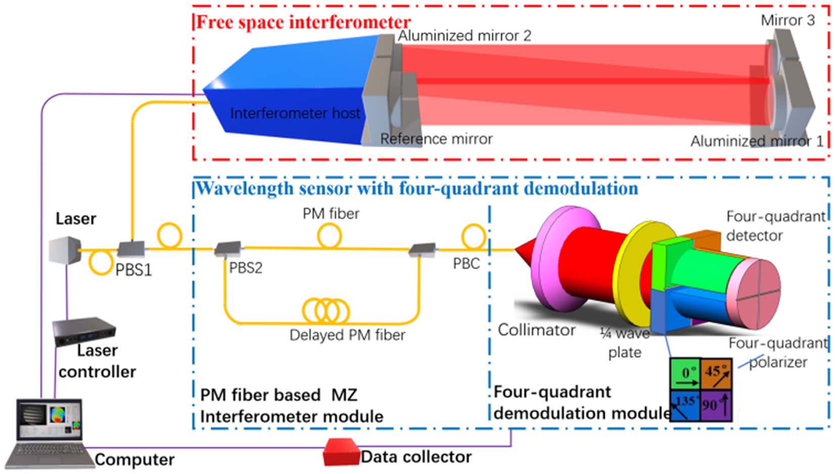
Figure 1 shows the wavelength monitoring setup of the wavelength phase-shifting interferometer based on the fiber wavelength sensor. The output PM fiber of the laser is connected with the fiber polarization beam splitter (PBS1). One output fiber of PBS1 connects the free-space interferometer in the red dashed box in Fig. 1 for phase-shifting test. The free-space interferometer employs mirror 1 and mirror 2 to fold the optical path in order to reduce the volume of the test optical path. The reference and test light beams reflected by the reference mirror and mirror 3, respectively, form the interference fringes on the detector of the interferometer. The phase changes of the interferometer cavity caused by the adjacent tuning wavelengths and are expressed as follows:
![]()
Figure 1.Optical path of the laser wavelength monitoring for the wavelength phase-shifting interferometer.
Tuning the wavelength of the laser to make the phase change interval of the interferometer cavity is the key to guaranteeing the measurement accuracy of the interferometer. In this paper, a PM fiber interferometer-based wavelength sensor with four-quadrant demodulation is proposed, the optical path of which is shown in the blue dashed box at the bottom of Fig. 1. The second output fiber of PBS1 is received by the fiber wavelength sensor with four-quadrant demodulation. The sensor is composed of the PM fiber Mach–Zender (MZ) interferometer[
In order to realize the real-time sensing of the wavelength, we use the spatial phase-shifting technology[
Therefore, the interference signals recorded by the four-quadrant detector with time can be expressed as
The change of the absolute phase with time can be written by
To sum up, we used the four-quadrant demodulation method to obtain the phase signals carrying the information of laser wavelength, so as to monitor the evolution of laser wavelength. As a spatial phase-shift demodulation technique, the method can effectively improve the time resolution of wavelength monitoring on the premise of ensuring the accuracy of phase-shift demodulation. Furthermore, the four-quadrant demodulation method guaranteed the utilization of light energy and reduced the insertion loss of the test light. It should be noted that the phase signal obtained by Eq. (6) has uncertainty of fringe order , so we cannot obtain the absolute change of the wavelength over time with . When the phase change of the adjacent sampling points is less than , can be obtained by phase unwrapping, expressed by , and the relative change of the laser wavelength in the wavelength phase-shifting interferometer can be obtained, as expressed by
3. Experimental Setup
The wavelength monitoring system of the wavelength phase-shifting interferometer was established in the experiment, as shown in Fig. 2. A tunable laser (Newfocus TLB7000) based on the Littman optical path was used as the test light source. The central wavelength of the laser was 638 nm, and it was output by a single-mode PM fiber (Nufern PM-630HP, slow axis alignment). The output power of the fiber was about 1 mW. The fiber PBS (MC Light, McPbs-630) is made of a free-space PBS coupled with a PM-630HP fiber. One output light of the fiber PBS was connected to the fiber ferrule connector (FC) interface of the 100 mm diameter free-space Fizeau interferometer (Nanjing Interfero Optoelectronics, Hi-Mac-100). The interferometer cavity is composed of a fused quartz standard mirror, a microcrystalline mirror, and two aluminized mirrors, which were used to fold the optical path. The length of the interferometer cavity is 2.75 m. The interferometer was placed on a vibration isolation table, and an interferometer cavity insulation device was installed to suppress the effects of vibration and temperature changes, as depicted in Fig. 2.
![]()
Figure 2.Physical photo of interferometer wavelength monitoring system based on the four-quadrant modulation wavelength sensor.
The fiber interferometer module is mainly composed of fiber devices and PM fibers. The fiber PBC (MC Light, MCPBC-630) is also made of a free-space PBS coupled with a PM-630HP fiber. Nufern’s PM630-HP single-mode PM fiber, with a length of 1.9 m, was also used for the delayed fiber. PM fibers and fiber devices are fused together and mounted on an aluminum plate with heat-insulating foam to suppress the influence of ambient temperature on the delay of the reference light and test light. The four-quadrant demodulation module is mainly composed of a collimating lens with a focal length of 60 mm, a 1/4 wave plate of the fourth-order (Taizhou Jingda Optoelectronics, QWP-633), a four-quadrant polarizing film (Suzhou Guangyu), and a four-quadrant detector (Shanghai Euoptics, OSQ50-IT, with the bandwidth of 200 kHz). The interference signals collected by the four-quadrant detector are converted into electrical signals by a multichannel analog/digital (A/D) converter (ALtaic Technology, USB3202N) with a sampling frequency of 250 kHz and recorded by a personal computer (Lenovo Legion, Intel Core I7 Processor). In the adjustment of the wavelength sensor, we found the orientation parameters of the polarization devices are very important to the wavelength sensing results, as depicted in Table 1.
| Devices | Parameters | Specification |
|---|---|---|
| PBS2 | Slow axis orientation of the common port fiber to that of the | |
| PBC | Slow axis orientation of the common port fiber to that of the | 0° or |
| QWP | Slow axis orientation of the QWP to that of the common port fiber of the PBC | |
| Four-quadrant polarizer | Transmission axis orientations of the polarizers in each quadrant | 0°/45°/90°/135° |
Table 1. The Orientation Parameters of the Polarization Devices
4. Results
In the experiment, the sinusoidal voltage signal with the frequency of 0.1 Hz, mean value of 30 V, and amplitude of 10 mV from the laser controller is set to drive the piezoelectric actuator of the tunable laser and make the wavelength of the laser change sinusoidally. Ideally, the mean value and amplitude of the four-channel interference signals output by the four-quadrant detector should be consistent. Thus, the mean value and amplitude of the four signals output by the wavelength sensor can be calibrated. Figure 3(a) shows the time-varying light intensity signals received by the four-quadrant detector in the wavelength tuning process of the laser. There is an angle interval of about 45° in the transmittance axis of the four polarizers of the four-quadrant polarizer, so the four-channel light signals present obvious phase shift. Due to the spot alignment error, the consistency of the four-quadrant detector, and the angle error of each quadrant polarizer, there are obvious background and contrast differences between the four-channel signals. After the laser is heat balanced, in Eq. (4) can be regarded as time independent. Therefore, the maximum and minimum values of each interference signal in Fig. 3(a) can be normalized. Figure 3(b) shows the normalized phase-shifting interference signals, and multiple interference peaks/valleys in each group of signals are basically consistent. The change of phase with time is obtained according to Eq. (5), as shown by the solid red line in Fig. 3(c). The phase values shown by the curve are wrapped in the range of to due to the arctangent function. The unwrapped phase is shown by the solid green line in Fig. 3(c), which coincides with the fitting cosine curve depicted by the blue dotted line in Fig. 3(c). The measured relative wavelength range is 0.71 pm, and the cosine signal period is about 10 s, which is consistent with the set value of the laser controller, indicating that the calibrated four-quadrant modulation wavelength sensor can correctly reflect the relative wavelength change of the laser. Figure 3(d) shows the measured wavelength results when the piezoelectric actuator of the laser is derived with 0.1 mV voltage step and 700 ms interval. The measured result by our sensor exhibits the same variation trend and wavelength range as that by the commercial wavelength meter (high finesse WS/8-2). In addition, according to the measured data, our sensor can achieve higher wavelength resolution (better than 0.005 nm) and shorter sampling interval (shorter than 0.1 ms), compared with the commercial instrument.
![]()
Figure 3.(a) Original intensity signals collected by the four-quadrant detector and (b) the normalized intensity signals, (c) the demodulated signals, and (d) wavelength monitoring results of the tunable laser.
The key to guaranteeing the measurement accuracy of wavelength phase-shifting interferometer is to control the tuning interval of laser wavelength and make the corresponding phase-shift interval . The step voltage of the laser is determined and set by the phase-shifting calibration method described in Ref. [3]. Interferograms are collected after the laser tuning interval (1000 ms), and the next tuning voltage of the laser is set after the image acquisition time (100 ms). The sequence of phase-shifting interferograms obtained is shown in Figs. 4(a)–4(f). The fringes in each column of the figure are the same, indicating that the phase shift of the interferometer is accurate. The orange dotted line in Fig. 5(a) presents the change of the laser control voltage with time during the phase-shifting process. The control voltage values, which were measured by the high-precision multimeter (Tektronix DMM4050 6-1/2), changed nine times in the 10 s range with the voltage step of 0.25 mV. When the control voltage changed, the output signals of the four-quadrant detector exhibited an obvious intensity jump, indicating that the wavelength of the laser was modulated at the time point. When the control voltage remains unchanged, the interference light intensity still changes relatively, indicating that the interference light intensity may be affected by the hysteresis effect[
![]()
Figure 4.Interference fringes recorded by the interferometer.
![]()
Figure 5.(a) Changes of the modulation voltage and output signals on the four-quadrant detector with time and (b) changes of the unwrapped phase and the relative wavelength with time.
The phase and relative wavelength changes of the interference signals can be calculated according to Eq. (5). Since the phase-shift interval of the interferogram sequence in Fig. 4 is , the phase jump caused by the 1.9 m delayed PM fiber (optical path difference is 2.75 m, about 1/2 of the cavity length of the free-space interferometer) is about . Thus, the wrapped phase calculated by Eq. (5) can be processed by conventional unwrapping algorithms. The change of phase and relative wavelength with time after unwrapping is shown by the solid blue line in Fig. 5(b). Eight interferograms (11 rad) were collected, and the phase change measured by the optical fiber sensor was about 5.4 rad. Thus, the phase change relation is consistent with that of the optical path difference of the two interferometers. The relative wavelength change of the laser is 0.275 pm according to Eq. (6). The illustration in Fig. 5(b) depicts the phase change measured by the wavelength sensor at the time when the tuning voltage changes. It can be seen that the response time of the laser tuning voltage is about 35 ms, and the phase change of the sensor is 0.4 rad. During the laser tuning interval (1000 ms) and image acquisition time (100 ms), the phase was still changing at the rate of 0.4 rad/s. The corresponding wavelength change rate was 0.01 pm/s. The change can be attributed to the hysteresis effect of the laser actuator and fiber temperature.
The wavelength measurement accuracy of a wavelength sensor is the key to the quality of wavelength monitoring in the phase-shifting process of the free-space interferometer. The measurement results of the sensor are mainly affected by the hysteresis effect of the laser and the temperature of the fiber. The output voltage values of the four-quadrant detector within 3000 s (50 min) are gathered, as shown in Fig. 6(a), without actuator voltage change of the tunable laser. The blue curve in Fig. 6(b) shows the variations of the demodulated phase/wavelength with time. The total change of wavelength is about 0.9 pm. The red curve in Fig. 6(b) shows the temperature change measured by a PT1000 temperature sensor and the high-precision multimeter (Tektronix DMM4050 6-1/2) in the same period. It can be seen that the wavelength change measured by the sensor has the same changing law as the fiber temperature. Thus, the wavelength measurement accuracy of the fiber sensor is affected by the measurement time when the fiber temperature is not controlled. The maximum change rate of the wavelength measured in Fig. 6(b) is about 0.001 pm/s. The change rate can be reduced if the temperature of the PM reference fiber and delay fiber is stabilized with a temperature controller. Since the wavelength change rate caused by the temperature is about 0.001 pm/s, the wavelength change (0.01 pm/s) in Fig. 5(b) is mainly caused by the hysteresis effect of the laser actuator during the laser tuning interval and image acquisition time.
![]()
Figure 6.(a) Output signal and (b) demodulation signal of the wavelength sensor without laser modulation.
It should be noted that the wavelength measurement sensitivity of the sensor is related to the optical path length of delay fiber. The longer the delay fiber is, the higher the sensitivity of the sensor becomes. In addition, due to the order uncertainty of the interference fringes collected by the four-quadrant detector, the wavelength measurement scheme in this paper can only measure the relative wavelength, and the transient phase change caused by the wavelength should be controlled within or even . The absolute length modulation system should be introduced into the interference arm of the fiber interferometer when the absolute wavelength is wanted. Furthermore, the sensor is relatively sensitive to the change of ambient temperature because of the fiber structure. An additional temperature control setup is required when higher precision of the sensor is wanted.
In the wavelength phase-shifting interferometer, the faster the wavelength shifts, the stronger the vibration resistance of the interferometer gets. In this paper, the interferometer adopts the step tuning method; that is, setting the tuning voltage, collecting the interferograms after a certain time, setting the next tuning voltage, and repeating the above steps. Therefore, the wavelength tuning speed of the interferometer is mainly affected by the tuning speed of the laser, the wavelength change speed in the hysteresis process of the laser actuator, and the acquisition speed of the interferogram. Capturing a series of phase-shifting interferograms during a fast tuning process of the tunable laser instead of the step tuning method is also a feasible method to improve the phase-shifting speed of the interferometer. Thus, the fiber wavelength sensor can be used to obtain the relative wavelength of the laser in real-time and feedback of the freezing signals of interferograms.
5. Conclusion
In this paper, we proposed a wavelength sensor based on a PM fiber interferometer to monitor the wavelength evolution of the wavelength phase-shifting interferometer. The four-quadrant demodulation method is used in the sensor. Thus, the wavelength signal can be obtained in a single shot, avoiding the temporal modulation with an electro-optical phase modulator. The proposed method can obtain the wavelength parameters, such as the response time and wavelength change speed of the interferometer, providing a low-cost wavelength sensing scheme for the wavelength phase-shifting interferometer. We will further carry out the constant temperature control of the optical fiber sensor and realize the closed-loop, fast wavelength tuning of the interferometer.
References
[1] L. L. Deck, J. A. Soobitsky. Phase-shifting via wavelength tuning in very large aperture interferometers. Proc. SPIE, 3782, 432(1999).
[2] L. Chai, Q. Xu, Y. Yu, Y. Deng, J. Xu. 500-mm-aperture wavelength-tuning phase-shifting interferometer. Proc. SPIE, 6150, 61500E(2006).
[3] R. Guo, J. Li, R. Zhu, C. Lei. Wavelength-tuned phase-shifting calibration based on the Fourier transform in time domain. Proceedings of Service Operations, Logistics and Informatics, 371(2009).
[4] L. Chang, T. He, C. Wang, Y. Yu. Multi-surface phase-shifting interferometry using harmonic frequency solution based on the total least squares. Opt. Lasers. Eng., 150, 106845(2022).
[5] Y. Zhao, Q. Wang, L. Meng, Y. Yao, S. Liu, N. Cui, L. Su, L. Zheng, H. Zhang, Y. Zhang. Anisotropy of the thermal and laser output properties in Yb,Nd:Sc2SiO5 crystal. Chin. Opt. Lett., 19, 041405(2021).
[6] L. Meng, P. Zhao, F. Meng, L. Chen, Y. Xie, Y. Wang, W. Bian, J. Jia, T. Liu, S. Zhang, J. Wang. Design and fabrication of a compact, high-performance interference-filter-based external-cavity diode laser for use in the China Space Station. Chin. Opt. Lett., 20, 021407(2022).
[7] M. Dobosz, M. Kożuchowski. Overview of the laser-wavelength measurement methods. Opt. Lasers. Eng., 98, 107(2017).
[8] H. G. Choi, T. D. Lee. Construction of a Michelson-type wavemeter and evaluation of its performances. New Phys. Sae Mulli, 70, 503(2020).
[11] N. K. Metzger, R. Spesyvtsev, G. D. Bruce, B. Miller, G. T. Maker, G. Malcolm, M. Mazilu, K. Dholakia. Harnessing speckle for a sub-femtometre resolved broadband wavemeter and laser stabilization. Nat. Commun., 8, 15610(2017).
[12] M. Mohagheghian, S. G. Sabouri. Laser wavelength measurement based on a digital micromirror device. IEEE Photon. Technol. Lett., 30, 1186(2018).
[13] E. Shan, Y. Li, B. Xu, C. Shen, C. Zhao, X. Dong, S. Jin. All fiber real-time laser wavelength measurement method based on faraday rotation effect. IEEE Photon. Technol. Lett., 27, 2246(2015).
[14] L. Yuan, L. Qiu. Research of wavelength calibration methods in laser wavelength measurement. Appl. Opt., 60, 4315(2021).
[15] Z. Ren, J. Li, R. Zhu, K. Cui, Q. He, H. Wang. Phase-shifting optical fiber sensing with rectangular-pulse binary phase modulation. Opt. Lasers. Eng., 100, 170(2018).
[16] Z. Hu, Z. Jing, J. Wang, S. Mei. Resonator fiber optic gyros with light time-division input and multiplexing output in clockwise and counterclockwise directions. Chin. Opt. Lett., 18, 030601(2020).
[17] C. L. Koliopoulos. Simultaneous phase-shift interferometer. Proc. SPIE, 1531, 119(1992).
[18] L. Ma, Y. Shen, J. Li, H. Zheng, T. Zou. Modeling hysteresis for piezoelectric actuators. J. Intell. Mater. Syst. Struct., 27, 1404(2016).

Set citation alerts for the article
Please enter your email address
© Copyright 2018-2021 | Chinese Laser Press. All Rights Reserved 沪ICP备15018463号-20