• Photonics Research
  • Vol. 12, Issue 5, 1044 (2024)
Xiaohan Jiang1、†, Wanying Liu1、†, Quan Xu1、*, Yuanhao Lang1, Yikai Fu2, Fan Huang1, Haitao Dai2, Yanfeng Li1, Xueqian Zhang1, Jianqiang Gu1, Jiaguang Han1、3、5, and Weili Zhang4、6
Author Affiliations
  • 1Center for Terahertz Waves, College of Precision Instrument and Optoelectronics Engineering, and Key Laboratory of Optoelectronics Information and Technology (Ministry of Education), Tianjin University, Tianjin 300072, China
  • 2Tianjin Key Laboratory of Low Dimensional Materials Physics and Preparing Technology, School of Science, Tianjin University, Tianjin 300072, China
  • 3Guangxi Key Laboratory of Optoelectronic Information Processing, School of Optoelectronic Engineering, Guilin University of Electronic Technology, Guilin 541004, China
  • 4School of Electrical and Computer Engineering, Oklahoma State University, Stillwater, Oklahoma 74078, USA
  • 5e-mail: jiaghan@tju.edu.cn
  • 6e-mail: weili.zhang@okstate.edu
  • show less
    DOI: 10.1364/PRJ.519701 Cite this Article Set citation alerts
    Xiaohan Jiang, Wanying Liu, Quan Xu, Yuanhao Lang, Yikai Fu, Fan Huang, Haitao Dai, Yanfeng Li, Xueqian Zhang, Jianqiang Gu, Jiaguang Han, Weili Zhang. On-chip terahertz orbital angular momentum demultiplexer[J]. Photonics Research, 2024, 12(5): 1044 Copy Citation Text show less
    Schematic views of the holographic design scheme for (a) hologram generation and (b) SP field reconstruction. The parameters are: w, width of the resonator; l, length of the resonator; and θ, rotation angle of the slit resonator.
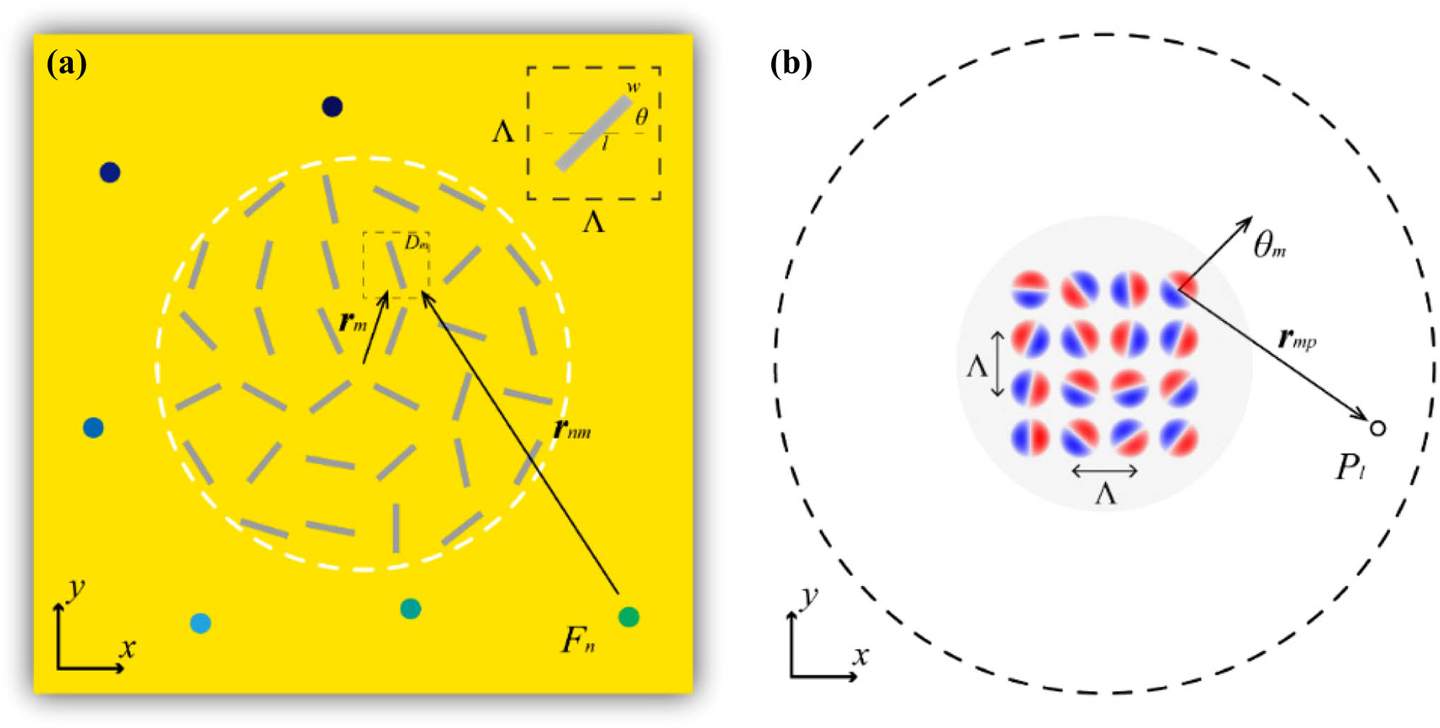
    Fig. 1. Schematic views of the holographic design scheme for (a) hologram generation and (b) SP field reconstruction. The parameters are: w, width of the resonator; l, length of the resonator; and θ, rotation angle of the slit resonator.
    Seven-channel on-chip OAM modes demultiplexing. (a) Schematic of the on-chip demultiplexer design. (b) Calculated distribution of the resonator orientation angles. (c) Microscopy image of the seven-channel OAM demultiplexer.
    Fig. 2. Seven-channel on-chip OAM modes demultiplexing. (a) Schematic of the on-chip demultiplexer design. (b) Calculated distribution of the resonator orientation angles. (c) Microscopy image of the seven-channel OAM demultiplexer.
    Results for the seven-channel OAM demultiplexer. (a) Calculated and measured SP intensity distributions. (b) Extracted intensities at focal spots. (c) Frequency spectra at focal spots.
    Fig. 3. Results for the seven-channel OAM demultiplexer. (a) Calculated and measured SP intensity distributions. (b) Extracted intensities at focal spots. (c) Frequency spectra at focal spots.
    Performance of the on-chip OAM demultiplexer under the incidence of hybrid OAM modes. (a), (d) Calculated demultiplexed SP intensity distributions under the incidence of two and three hybrid OAM modes, respectively. (b), (e) Corresponding measured results. (c), (f) Extracted intensities at focal spots corresponding to the measured results in (b) and (e).
    Fig. 4. Performance of the on-chip OAM demultiplexer under the incidence of hybrid OAM modes. (a), (d) Calculated demultiplexed SP intensity distributions under the incidence of two and three hybrid OAM modes, respectively. (b), (e) Corresponding measured results. (c), (f) Extracted intensities at focal spots corresponding to the measured results in (b) and (e).
    Generation of incident vortex beams. (a) Schematic of an efficient all-dielectric vortex plate. (b) Microscopy image of a fabricated vortex plate sample (l=2). The inset at the top left corner is the schematic of the square meta-atom, and the image at the top right corner is the anti-reflection layer. (c) Photo of the experimental setup.
    Fig. 5. Generation of incident vortex beams. (a) Schematic of an efficient all-dielectric vortex plate. (b) Microscopy image of a fabricated vortex plate sample (l=2). The inset at the top left corner is the schematic of the square meta-atom, and the image at the top right corner is the anti-reflection layer. (c) Photo of the experimental setup.
    Measured intensity (first and third rows) and phase (second and fourth rows) distributions of vortex beams with l=−6 to l=6 generated by high-efficiency vortex plates.
    Fig. 6. Measured intensity (first and third rows) and phase (second and fourth rows) distributions of vortex beams with l=6 to l=6 generated by high-efficiency vortex plates.
    Measured results of vortex beams with hybrid OAM modes. (a), (b) Measured intensity distributions of vortex beams with two hybrid OAM modes of l=−2 and 2 and three OAM modes of l=−2, 2, and 4. (c), (d) Normalized intensities of the OAM modes corresponding to (a) and (b) (for l values of −6 to 6) as a function of the radial ring on the beam.
    Fig. 7. Measured results of vortex beams with hybrid OAM modes. (a), (b) Measured intensity distributions of vortex beams with two hybrid OAM modes of l=2 and 2 and three OAM modes of l=2, 2, and 4. (c), (d) Normalized intensities of the OAM modes corresponding to (a) and (b) (for l values of 6 to 6) as a function of the radial ring on the beam.
    Six-channel on-chip OAM modes demultiplexing. (a) Schematic of the on-chip demultiplexer design. (b) Calculated distribution of the resonator orientation angles. (c) Microscopy image of the six-channel OAM demultiplexer.
    Fig. 8. Six-channel on-chip OAM modes demultiplexing. (a) Schematic of the on-chip demultiplexer design. (b) Calculated distribution of the resonator orientation angles. (c) Microscopy image of the six-channel OAM demultiplexer.
    Results for the six-channel OAM demultiplexer. (a) Calculated and measured SP intensity distribution. (b) Extracted intensities at focal spots. (c) Frequency spectra at focal spots.
    Fig. 9. Results for the six-channel OAM demultiplexer. (a) Calculated and measured SP intensity distribution. (b) Extracted intensities at focal spots. (c) Frequency spectra at focal spots.
    Nine-channel on-chip OAM and wavelength demultiplexer. The calculated results are implemented under the incidences of topological charges of −2, 0, and 2 and wavelengths of 600 μm, 500 μm, and 400 μm, respectively.
    Fig. 10. Nine-channel on-chip OAM and wavelength demultiplexer. The calculated results are implemented under the incidences of topological charges of 2, 0, and 2 and wavelengths of 600 μm, 500 μm, and 400 μm, respectively.
    Xiaohan Jiang, Wanying Liu, Quan Xu, Yuanhao Lang, Yikai Fu, Fan Huang, Haitao Dai, Yanfeng Li, Xueqian Zhang, Jianqiang Gu, Jiaguang Han, Weili Zhang. On-chip terahertz orbital angular momentum demultiplexer[J]. Photonics Research, 2024, 12(5): 1044
    Download Citation