
Ke Tian, Weifeng Ding, Zhaoying Wang. Dead-zone-free atomic magnetometer based on hybrid Poincaré beams[J]. Photonics Research, 2024, 12(5): 1093
- Photonics Research
- Vol. 12, Issue 5, 1093 (2024)
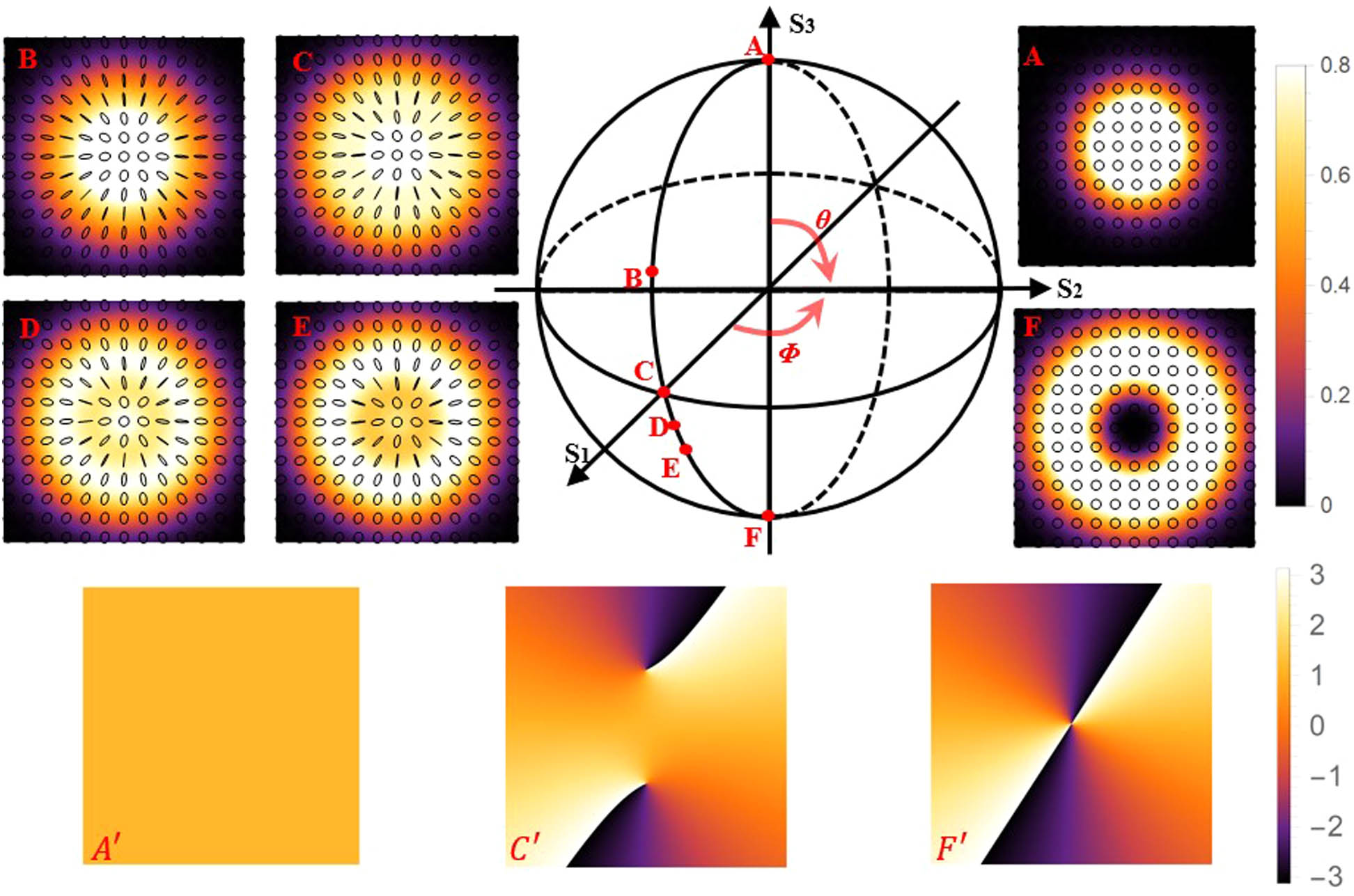
Fig. 1. The hybrid Poincaré sphere and the polarization distributions. A–F: (0°, 0°), (64°, 0°), (90°, 0°), (102°, 0°), (110°, 0°), and (180°, 0°) in order. A’, C’, and F’ are the phase profiles of A, C, and F, respectively.

Fig. 2. The normalized absorption signal amplitude at 90° and 54.7° as a function of the equivalent ellipticity.
Fig. 3. (a) Schematic of the experimental setup. (b) The phase diagram loading by SLM. HWP: half-wave plate; PBS: polarization beam splitter; QWP: quarter-wave plate; M: mirror; A: aperture; SLM: spatial light modulator; PD: photodiode.
Fig. 4. The amplitude of the OMR signal as a function of the angle between the beam propagation axis and the direction of the external magnetic fields in the X -Z plane. The inset pictures represent the proportion of the intensity distribution of the 0-LGB, the 2-LGB, and the whole beam in order. (a) Theoretical results. (b) Experimental results.
Fig. 5. Amplitude of the OMR signal as a function of the angle ϕ X -Y plane.

Set citation alerts for the article
Please enter your email address
© Copyright 2018-2021 | Chinese Laser Press. All Rights Reserved 沪ICP备15018463号-20