
Quan Sheng, Jingni Geng, Tianchang Liu, Shijie Fu, Wei Shi, Jianquan Yao. A continuous-wave Nd:YVO4 -KGW intracavity Raman laser with over 34% diode-to-Stokes optical efficiency[J]. High Power Laser Science and Engineering, 2024, 12(2): 02000e19
- High Power Laser Science and Engineering
- Vol. 12, Issue 2, 02000e19 (2024)
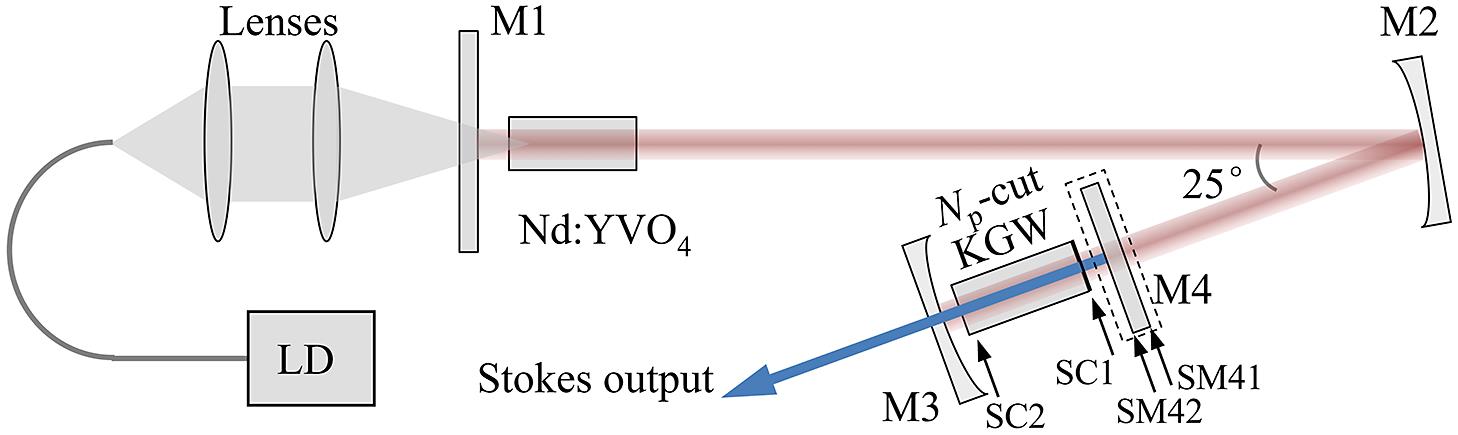
Fig. 1. Experimental setup of the Nd:YVO4-KGW intracavity Raman laser with Stokes HR coating on one of the crystal end-faces and on a separate mirror.

Fig. 2. Stokes output power and fundamental laser leakage as a function of incident LD pump power, with the two different cavity arrangements.
Fig. 3. Typical Stokes spectra (a), (b) and beam profiles (c), (d) at different Stokes output powers, with the HR-coated KGW crystal.
Fig. 4. Optical efficiency P S_out/P P of the Raman laser as a function of the Stokes and fundamental round-trip losses, with the incident pump power of (a) 24.8 W and (b) 40.9W, respectively. The calculation used a 270-μm fundamental laser radius in the laser crystal, 110-μm fundamental laser radius and Stokes beam radius in the KGW crystal and 0.7% output coupling for the Stokes wave.
Fig. 5. Schematic of the influences of the end-face curvature on the cavity scheme.
Fig. 6. Thermo-optically induced negative thermal lens focal length and (single) end-face curvature induced positive thermal lens focal length as a function of Stokes power generated in the KGW crystal, in p[mm]p orientation. The fundamental and Stokes wavelengths are 1064 and 1177 nm, respectively. The Stokes beam radius in the KGW crystal used in the calculation is 110 μm.
Fig. 7. TEM00 mode Stokes beam size evolution with thermo-optically induced f tn in the KGW crystal with the two different cavity arrangements, with the relationship between f tn and f te considered.
| |||||||||||||||||||||||||||||||||||||||||||||||||||||||||||||||
Table 1. The reflectivities of the AR coatings and transmittances of the HR coating of each surface provided by the manufacturers.

Set citation alerts for the article
Please enter your email address
© Copyright 2018-2021 | Chinese Laser Press. All Rights Reserved 沪ICP备15018463号-20