
Chunlei Sun, Chuyu Zhong, Maoliang Wei, Hui Ma, Ye Luo, Zequn Chen, Renjie Tang, Jialing Jian, Hongtao Lin, Lan Li. Free-spectral-range-free filters with ultrawide tunability across the S + C + L band[J]. Photonics Research, 2021, 9(6): 1013
- Photonics Research
- Vol. 9, Issue 6, 1013 (2021)
Abstract
1. INTRODUCTION
Integrated optical filters used for spectrum manipulation are among the most significant components in photonic systems on chip, enabling many advanced applications in optical communication and computing, spectroscopy, sensing, and high-precision measurement [1–5]. As the fundamental building block for wavelength (de)multiplexing, optical filters are highly desired in wavelength-division-multiplexing (WDM) technology. WDM technology has been widely adapted for flexible and effective filtering and combining of hundreds of nanometer-wide signals in optical communication applications. Besides, WDM technology is also one of the key technologies to construct sensor networks to realize quasi-distributed multisite and multiparameter sensing, which can obtain the spatial distribution and time-varying information of the measured field simultaneously. A filter with a large free spectral range (FSR) can effectively increase the number of independent sensors on a single sensor link and realize simultaneous sensing of multiple loci and parameters. Therefore, an integrated photonic filter with a large FSR and a small footprint allowing a large number of multiplexed channels is crucial.
The filters based on silicon photonics technology with different interferometric structures mainly include echelle diffraction gratings (EDGs) [6,7], arrayed-waveguide gratings (AWGs) [8–10], microring resonators (MRRs) [11–16], Mach–Zehnder interferometers (MZIs) [17–21], Fabry–Perot (F-P) cavities [22–24], Bragg gratings [3,25–28], and nanobeam cavities [29–33], and their FSR usually ranges from several nanometers to tens of nanometers. Recently, many efforts have been devoted to achieving a large FSR covering multiple wavelength channels by optimizing the filter cavity’s resonance structures. The FSR of MRRs could be increased to as large as 93 nm by using a submicrometer bending radius [16], while the FSR of the F-P cavity could be larger than 30 nm [24]. For the nanobeam cavity, multiple resonant modes are usually excited in the cavity with a tens-of-nanometers FSR. The limited FSR of the aforementioned integrated filters prevents their use in applications that require numerous channels.
Thus, various design strategies have been adopted to extend the filter’s FSR or obtain an FSR-free response in the operating wavelength range. Contradirectional couplers (CDCs) have been designed based on the photonic bandgap feature of Bragg grating. Since the bandwidth of Bragg gratings is usually disproportionate to the length, a device using shallow grating might be quite long [28]. To further reduce the size of filters, CDC is introduced into one or two coupling regions of the MRR to achieve a major resonance [34]. Maximum side-mode suppressions at all other undesired resonant wavelengths will be achieved provided that the stopband of the grating is twice the MRR’s FSR. Another way is to apply the Vernier effect to realize quite large FSR by cascading multiple MRRs with different FSRs [35]. Nevertheless, it is difficult to achieve the resonant wavelength alignment since the stringent requirement for design and fabrication accuracy must be satisfied. Extra active tuning control is usually introduced to compensate for the fabrication error. Therefore, an ideal integrated filter that combines the large FSR and high side-mode suppression ratio to avoid precise wavelength alignment is highly desirable.
Sign up for Photonics Research TOC. Get the latest issue of Photonics Research delivered right to you!Sign up now
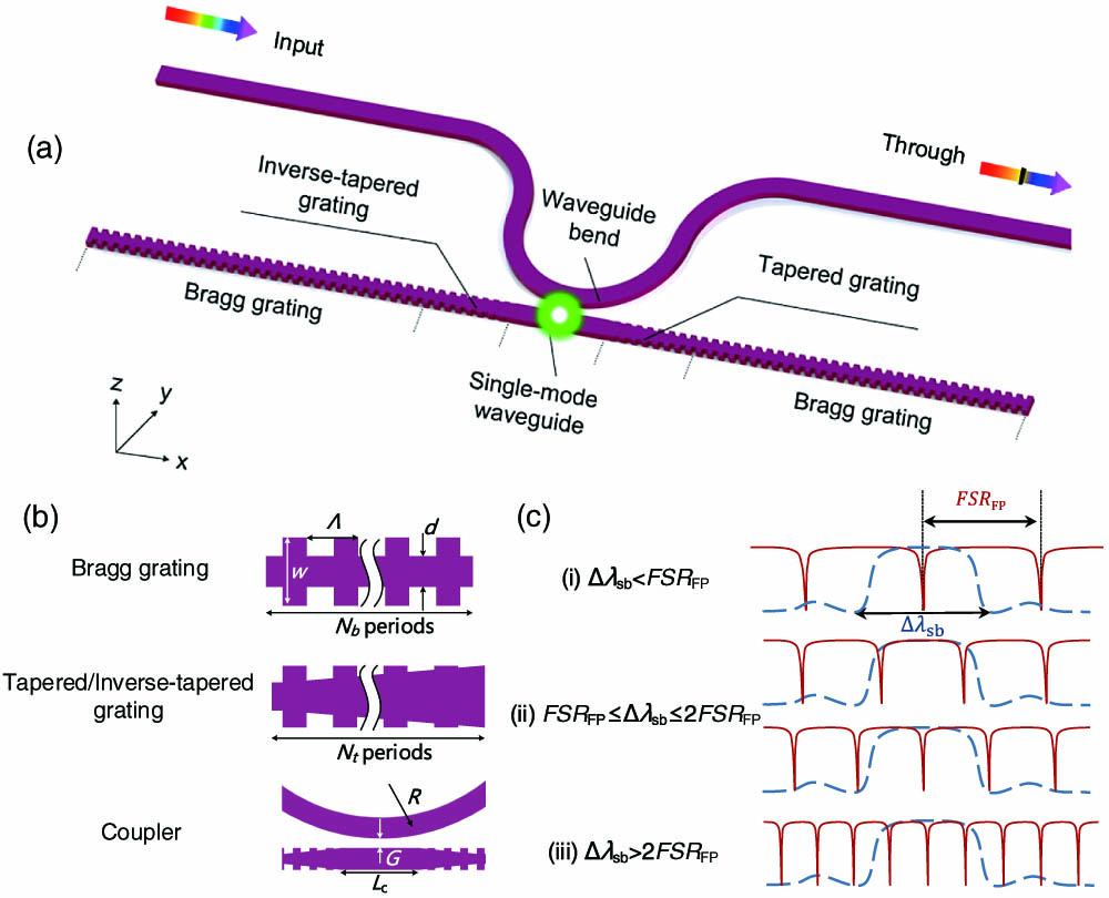
Figure 1.(a) Schematic of our proposed filter with a grating-assisted F-P cavity selectively trapping a single narrowband beam in the ultrawide waveband range. (b) Some key parts of the filter as well as the design parameters. (c) Typical spectral response of a Bragg grating (dashed blue curve) and F-P cavity with ideal mirrors (solid red curve). When the stopband of the Bragg grating is smaller than the FSR of the F-P cavity,
In this paper, we address the challenges in integrated optical filters by theory, simulation, and experimental analysis for on-chip ultra-wideband optical signal filters, which simultaneously achieve FSR-free operation and subnanometer optical bandwidths. First, we introduce the structure of the filter consisting of a series of key parts that take up coupling, filtering, mode matching, and reflection. Then we introduce the mechanism of FSR-free spectral response in the grating-assisted F-P cavity by investigating and comparing the stopband of Bragg grating and FSR of the F-P cavity. We show that there is only a single deep dip in a hundreds of nanometers waveband when grating depth and cavity length are adopted appropriately to ensure the stopband of the Bragg grating is smaller than the FSR of the F-P cavity. Fabricated devices achieve an FSR-free response in a record-large waveband ( band) and a flat-top response at nonresonant wavelengths.
2. DEVICE DESIGN AND OPERATION PRINCIPLE
Figure 1(a) shows the schematic of the filter, consisting of a side-coupled waveguide bend and a Bragg grating-assisted F-P cavity. A central single-mode waveguide is embraced by two Bragg gratings as side-reflection mirrors, forming the F-P cavity. A tapered/inverse-tapered grating is used to connect the central waveguide and the Bragg gratings to achieve mode matching between the waveguide and Bragg mirror, minimizing the scattering loss at the cavity–mirror interface. The Bragg grating consists of wide and narrow waveguides arranged alternately and periodically. For the tapered/inverse-tapered grating, the central transom is linearly tapered from the wide/narrow to the narrow/wide waveguide. The light from the input waveguide is coupled into the center of the F-P cavity. The light at resonant wavelength is trapped and enhanced in the cavity, while the nonresonant wavelength is directionally routed to the through waveguide. The parameters to be designed for the filter include the width and length of the central waveguide and , the bend radius , the coupling gap , the perturbation period , and the width of the wide and narrow waveguide of Bragg grating and , as illustrated in Fig. 1(b), as well as the period number of the Bragg grating and tapered grating and . The spectral response of the filter mainly depends on the stopband of the Bragg grating and FSR of the F-P cavity with ideal mirrors , as shown in Fig. 1(c). The stopband is defined here as the width between the null points of the central lobe.
The relation between , , and is plotted in Fig. 2(a). The is attained by the Bragg equation, and is calculated by using three-dimensional (3D) finite-difference time-domain (FDTD) simulations. The decreases as increases, while increases as increases. Figure 2(b) shows the calculated FSR as is varied. The FSR is given by
![]()
Figure 2.(a) Calculated central wavelength
The FSR-free feature of the filter is determined by the relation of and . To address the issue, different values for are chosen to calculate the ratio of for , 300, and 360 nm as shown in Fig. 2(c). Three regions with different colors correspond to the abovementioned cases (i)–(iii). We calculate the filters’ spectral responses for , 4, 6, and 14 μm with , corresponding to cases (i)–(iii). For of case (i), we obtain the FSR-free response due to smaller than 1. For and 6 μm of case (ii), double dips and one dip are excited, respectively. For of case (iii), multiple dips are excited due to . The simulated results fully agree with the discussions illustrated in Fig. 1(c). As a demonstration, Fig. 3(a) exhibits the spectral transmission of the filter for transverse-electric (TE) polarization with , , , , , and from 1400 to 1620 nm. Since the ridge waveguide based on a 220 nm silicon-on-insulator (SOI) platform with 150 nm etching depth is adopted, transverse-magnetic (TM) polarization is not supported in such a waveguide structure. TM polarization can work for strip waveguide, and the device will be FSR free if case (i) () is satisfied. We can see only a single dramatic dip at 1521 nm in the ultralarge wavelength range of 220 nm, whereas there is a flat-top response at nonresonant wavelengths. Figure 3(b) exhibits the electric field distribution of the whole structure at the wavelengths of 1400, 1521, 1522, and 1620 nm. For the light at the wavelengths of 1400 and 1620 nm out of the stopband, the filter is considered a double-waveguide directional coupler. Hence, the light cannot be enhanced in the F-P cavity but is coupled into the right Bragg grating. Since the coupling length is short, the insertion loss out of the stopband could be neglected. For the wavelength of 1522 nm in the stopband, the light is coupled into the cavity, then reflected by the Bragg mirror, and finally transferred to the through port. For the resonant wavelength of 1521 nm, the light is coupled into the cavity, and the power in the cavity is enhanced until a dynamic balance between coupled power, outcoupled power, and lossy power is achieved. At the critical coupling condition, the light is like being trapped in the cavity, and almost no power is coupled out to the through port.
![]()
Figure 3.(a) Calculated transmission of the filter in the wavelength range of 1400–1620 nm. (b) Simulated electric field distribution at the wavelengths of 1400, 1521, 1522, and 1620 nm. The white arrow shows the direction of the injected light.
3. DEVICE FABRICATION AND CHARACTERIZATION
The proposed filter was based on SOI with a 220 nm top layer and was fabricated after the exposure of electron beam lithography (EBL, Raith Voyager) followed by the dry etching process in inductively coupled plasma (ICP) equipment (Samco). The fabricated devices have rib waveguides with an etching depth of 150 nm and a top oxide cladding. A broadband tunable laser system (Santec full-band TSL-550) was used to characterize the fabricated devices. The measured spectral responses were normalized with respect to the transmission of a straight waveguide connected with grating couplers on the same chip. The resolution is 5 pm in the measurements. Instead of utilizing commonly used shallow-etched grating couplers with 70 nm depth, here, 150 nm etched grating couplers, which have a much slower roll-off despite slightly lower peak coupling efficiency, were applied to enable broadband performance characterization. Figure 4 illustrates the scanning electron microscope (SEM) image of the filter and the enlarged key parts.
![]()
Figure 4.SEM image of the fabricated filter as well as the insets illustrating the zoom-in views of Bragg gratings and the central coupling region.
The normalized spectral response at through port shows a single deep dip with an extinction ratio of about 9.3 dB at 1485.6 nm in a 200 nm wavelength span from 1400 to 1600 nm as illustrated in Fig. 5(a). Due to the bandwidth limit of the grating coupler, the coupling efficiency is too low to be detected below 1400 nm. The inset shows the zoom-in view of the plot around the resonant wavelength with 3 dB bandwidth of 0.25 nm and Q factor of 5942. The key parameters of , , , , , and are adopted. The Q factor can be improved by optimizing the EBL and ICP dry etching process to decrease the roughness of the waveguide sidewalls. Figure 5(b) shows the multiple measured curves associated with various pitches. As the pitch experiences a large deviation from 283 to 323 nm, the resonant wavelength shifts from 1430.06 to 1552.83 nm. Also, relatively dense filtering ( channel spacing) can be achieved by adopting a small deviation of the pitch of 2 nm, and the channel spacing can be reduced further by tuning
![]()
Figure 5.(a) Measured transmission spectrum of the fabricated device. The inset shows the spectral response around the resonant wavelength. (b) Measured transmission spectra of the fabricated devices with various pitches.
4. REFRACTIVE INDEX AND TEMPERATURE SENSING
To study the sensing capabilities of the filter, we arrange our experimental steps as follows. First, we place the chip without top cladding on the testing stage and cover it with refractive index liquids (Cargille Laboratories, USA), whose refractive index is varied as four values of 1.30, 1.42, 1.54, and 1.66. The transmission spectra are plotted in Fig. 6(a). We can see clearly that the resonant wavelength redshifts when the refractive index increases and the FSR-free feature still remains, and the dip tends to be deeper. There is a perfectly linear relationship between the resonant wavelength shift and the refractive index change as shown in the inset of Fig. 6(a). The sensitivity of the refractive index, namely, the slope of the fitted curve, is calculated as . Second, we deposit 1 μm thick silica onto the chip as the top cladding and do the testing on a high-precision temperature console stage. The chip is heated from 293 to 373 K with an increasing step of 20 K, and the transmission spectra are shown in Fig. 6(b). The inset shows a linear fit to the resonant wavelength shifts as a function of temperature. The sensitivity of temperature is calculated as .
![]()
Figure 6.Measured transmission responses of the filter (a) covered under liquids with various refractive indices, and (b) heated by increasing temperature. The insets in (a) and (b) show linear fits of the resonant wavelength shifts versus refractive index and temperature, respectively. (c) Measured transmission response of the device consisting of five FSR-free filters with different pitches cascaded in series. The inset shows the optical microscope view of the multichannel filter.
To investigate the possibility of multiparameter sensing using WDM technology, we designed and fabricated a multichannel filter consisting of five of our proposed filters with diverse pitches in cascade. The pitch varies from 287 to 327 nm with a step of 20 nm. The measured transmission response of the multichannel filter is illustrated in Fig. 6(c). Five deep dips corresponding to five FSR-free filters with different pitches occur in the spectrum. Therefore, it is promising to achieve quasi-distributed multisite and multiparameter sensing through specific treatment for each filter unit such as surface modification [37].
5. CONCLUSION
In summary, we have proposed and fabricated a side-coupled Bragg-grating-assisted F-P filter with an FSR-free response. By elaborately designing the stopband of the Bragg grating and the FSR of the F-P cavity, only one deep resonance dip with subnanometer bandwidth is realized in a record-large operation waveband ( band). The well-designed filter has also been applied as the basic sensing unit for both the refractive index and temperature measurement, showing a sensitivity of 52.34 nm/RIU for refractive index and 75.4 pm/K for temperature. Our results suggest that FSR-free filters can be adapted in many photonic integrated platforms to create highly attractive applications, including but not limited to optical communication and sensing. Besides, we also demonstrate a multichannel filter with five such FSR-free filter units cascaded in series, which opens up the possibility of on-chip integrated photonics for quasi-distributed multisite and multiparameter sensing.
Acknowledgment
Acknowledgment. We thank Westlake Center for Micro/Nano Fabrication, Instrumentation and Service Center for Physical Sciences at Westlake University and ZJU Micro-Nano Fabrication Center at Zhejiang University for the facility support.
References
[1] D. Pérez, I. Gasulla, L. Crudgington, D. J. Thomson, A. Z. Khokhar, K. Li, W. Cao, G. Z. Mashanovich, J. Capmany. Multipurpose silicon photonics signal processor core. Nat. Commun., 8, 636(2017).
[2] E. S. Magden, N. Li, M. Raval, C. V. Poulton, A. Ruocco, N. Singh, D. Vermeulen, E. P. Ippen, L. A. Kolodziejski, M. R. Watts. Transmissive silicon photonic dichroic filters with spectrally selective waveguides. Nat. Commun., 9, 3009(2018).
[3] W. Zhang, J. Yao. A fully reconfigurable waveguide Bragg grating for programmable photonic signal processing. Nat. Commun., 9, 1396(2018).
[4] W. Zhang, J. Yao. Photonic integrated field-programmable disk array signal processor. Nat. Commun., 11, 406(2020).
[5] D. Pérez-López, A. López, P. DasMahapatra, J. Capmany. Multipurpose self-configuration of programmable photonic circuits. Nat. Commun., 11, 6359(2020).
[6] R. Cheng, C.-L. Zou, X. Guo, S. Wang, X. Han, H. X. Tang. Broadband on-chip single-photon spectrometer. Nat. Commun., 10, 4104(2019).
[7] D. Melati, P. G. Verly, A. Delâge, S. Wang, J. Lapointe, P. Cheben, J. H. Schmid, S. Janz, D.-X. Xu. Compact and low crosstalk echelle grating demultiplexer on silicon-on-insulator technology. Electronics, 8, 687(2019).
[8] S. Chen, X. Fu, J. Wang, Y. Shi, S. He, D. Dai. Compact dense wavelength-division (de)multiplexer utilizing a bidirectional arrayed-waveguide grating integrated with a Mach–Zehnder interferometer. J. Lightwave Technol., 33, 2279-2285(2015).
[9] A. van Wijk, C. R. Doerr, Z. Ali, M. Karabiyik, B. I. Akca. Compact ultrabroad-bandwidth cascaded arrayed waveguide gratings. Opt. Express, 28, 14618-14626(2020).
[10] E. J. Stanton, N. Volet, J. E. Bowers. Silicon arrayed waveguide gratings at 2.0-μm wavelength characterized with an on-chip resonator. Opt. Lett., 43, 1135-1138(2018).
[11] S. N. Zheng, J. Zou, H. Cai, J. F. Song, L. K. Chin, P. Y. Liu, Z. P. Lin, D. L. Kwong, A. Q. Liu. Microring resonator-assisted Fourier transform spectrometer with enhanced resolution and large bandwidth in single chip solution. Nat. Commun., 10, 2349(2019).
[12] R. A. Cohen, O. Amrani, S. Ruschin. Response shaping with a silicon ring resonator via double injection. Nat. Photonics, 12, 706-712(2018).
[13] Y.-H. Lai, M.-G. Suh, Y.-K. Lu, B. Shen, Q.-F. Yang, H. Wang, J. Li, S. H. Lee, K. Y. Yang, K. Vahala. Earth rotation measured by a chip-scale ring laser gyroscope. Nat. Photonics, 14, 345-349(2020).
[14] D. Hu, C. Zou, H. Ren, J. Lu, Z. Le, Y. Qin, S. Guo, C. Dong, W. Hu. Multi-parameter sensing in a multimode self-interference micro-ring resonator by machine learning. Sensors, 20, 709(2020).
[15] P. Chen, S. Chen, X. Guan, Y. Shi, D. Dai. High-order microring resonators with bent couplers for a box-like filter response. Opt. Lett., 39, 6304-6307(2014).
[16] D. Liu, C. Zhang, D. Liang, D. Dai. Submicron-resonator-based add-drop optical filter with an ultra-large free spectral range. Opt. Express, 27, 416-422(2019).
[17] F. Horst, W. M. J. Green, S. Assefa, S. M. Shank, Y. A. Vlasov, B. J. Offrein. Cascaded Mach-Zehnder wavelength filters in silicon photonics for low loss and flat pass-band WDM (de-)multiplexing. Opt. Express, 21, 11652-11658(2013).
[18] Q. Deng, L. Liu, R. Zhang, X. Li, J. Michel, Z. Zhou. Athermal and flat-topped silicon Mach-Zehnder filters. Opt. Express, 24, 29577-29582(2016).
[19] H. Xu, L. Liu, Y. Shi. Polarization-insensitive four-channel coarse wavelength-division (de)multiplexer based on Mach-Zehnder interferometers with bent directional couplers and polarization rotators. Opt. Lett., 43, 1483-1486(2018).
[20] D. M. Kita, B. Miranda, D. Favela, D. Bono, J. Michon, H. Lin, T. Gu, J. Hu. High-performance and scalable on-chip digital Fourier transform spectroscopy. Nat. Commun., 9, 4405(2018).
[21] M. C. Souza, A. Grieco, N. C. Frateschi, Y. Fainman. Fourier transform spectrometer on silicon with thermo-optic non-linearity and dispersion correction. Nat. Commun., 9, 665(2018).
[22] W. Zhang, N. Ehteshami, W. Liu, J. Yao. Silicon-based on-chip electrically tunable sidewall Bragg grating Fabry-Perot filter. Opt. Lett., 40, 3153-3156(2015).
[23] Z. Yu, H. Cui, X. Sun. Genetically optimized on-chip wideband ultracompact reflectors and Fabry-Perot cavities. Photon. Res., 5, B15-B19(2017).
[24] Y. Wang, S. Gao, K. Wang, H. Li, E. Skafidas. Ultra-broadband, compact, and high-reflectivity circular Bragg grating mirror based on 220 nm silicon-on-insulator platform. Opt. Express, 25, 6653-6663(2017).
[25] D. Oser, F. Mazeas, X. Le Roux, D. Pérez‐Galacho, O. Alibart, S. Tanzilli, L. Labonté, D. Marris‐Morini, L. Vivien, É. Cassan. Coherency‐broken Bragg filters: overcoming on‐chip rejection limitations. Laser Photon. Rev., 13, 1800226(2019).
[26] X. Wang, Y. Wang, J. Flueckiger, R. Bojko, A. Liu, A. Reid, J. Pond, N. A. F. Jaeger, L. Chrostowski. Precise control of the coupling coefficient through destructive interference in silicon waveguide Bragg gratings. Opt. Lett., 39, 5519-5522(2014).
[27] H. Yun, M. Hammood, S. Lin, L. Chrostowski, N. A. F. Jaeger. Broadband flat-top SOI add-drop filters using apodized sub-wavelength grating contradirectional couplers. Opt. Lett., 44, 4929-4932(2019).
[28] D. T. H. Tan, K. Ikeda, Y. Fainman. Cladding-modulated Bragg gratings in silicon waveguides. Opt. Lett., 34, 1357-1359(2009).
[29] S. I. Halimi, S. Hu, F. O. Afzal, S. M. Weiss. Realizing high transmission intensity in photonic crystal nanobeams using a side-coupling waveguide. Opt. Lett., 43, 4260-4263(2018).
[30] P. Liu, Y. Shi. Simultaneous measurement of refractive index and temperature using cascaded side-coupled photonic crystal nanobeam cavities. Opt. Express, 25, 28398-28406(2017).
[31] Y. Chen, W. S. Fegadolli, W. M. Jones, A. Scherer, M. Li. Ultrasensitive gas-phase chemical sensing based on functionalized photonic crystal nanobeam cavities. ACS Nano, 8, 522-527(2013).
[32] Q. Qiao, J. Xia, C. Lee, G. Zhou. Applications of photonic crystal nanobeam cavities for sensing. Micromachines, 9, 541(2018).
[33] Q. Quan, P. B. Deotare, M. Loncar. Photonic crystal nanobeam cavity strongly coupled to the feeding waveguide. Appl. Phys. Lett., 96, 203102(2010).
[34] N. Eid, R. Boeck, H. Jayatilleka, L. Chrostowski, W. Shi, N. A. F. Jaeger. FSR-free silicon-on-insulator microring resonator based filter with bent contra-directional couplers. Opt. Express, 24, 29009-29021(2016).
[35] R. Boeck, N. A. F. Jaeger, N. Rouger, L. Chrostowski. Series-coupled silicon racetrack resonators and the Vernier effect: theory and measurement. Opt. Express, 18, 25151-25157(2010).
[36] R. P. Stanley, R. Houdré, U. Oesterle, M. Gailhanou, M. Ilegems. Ultrahigh finesse microcavity with distributed Bragg reflectors. Appl. Phys. Lett., 65, 1883-1885(1994).
[37] G. J. Triggs, Y. Wang, C. P. Reardon, M. Fischer, G. J. O. Evans, T. F. Krauss. Chirped guided-mode resonance biosensor. Optica, 4, 229-234(2017).

Set citation alerts for the article
Please enter your email address
© Copyright 2018-2021 | Chinese Laser Press. All Rights Reserved 沪ICP备15018463号-20