
Kai Sun, Zi-Jian Zhang, Fei Meng, Bin Cheng, Zhu Cao, Jin-Shi Xu, Man-Hong Yung, Chuan-Feng Li, Guang-Can Guo. Experimental verification of group non-membership in optical circuits[J]. Photonics Research, 2021, 9(9): 1745
- Photonics Research
- Vol. 9, Issue 9, 1745 (2021)
Abstract
1. INTRODUCTION
Quantum effect can be used to enhance information processing in many ways. Besides speeding up solving certain problems [1–3], quantum computers can also be used to construct novel interactive proof systems (IPSs) [4–6], which leads to fruitful studies in blind quantum computing [7–9], quantum zero-knowledge proof systems [10,11], and multiprover IPSs [12,13]. An IPS involves a verifier and (potentially multiple)
IPSs can be used to classify decision problems, the problems whose answers can only be YES or NO. For example, nondeterministic polynomial time (NP), one of the most important complexity classes, can be described by an IPS, with a classical verifier and a single computationally unbounded prover exchanging one round of classical message [14,15]. Specifically, NP contains decision problems that, for a YES instance, there exists certain proof message, with which the YES instance can be verified in polynomial time by a classical computer. can be generalized to the quantum realm naturally and the quantum analog is called quantum Merlin–Arthur (QMA) [15,16]. In QMA, the proof message is replaced by a quantum state, and the verifier can use a quantum computer to process it [17,18].
Since a classical verifier can be simulated by a quantum computer and a classical message can be described by a quantum state, every problem belonging to NP is also in QMA [15,16], i.e., . However, it remains an unsolved problem whether is strictly larger than , and the group nonmembership (GNM) problem is believed to be a possible candidate that falls in QMA but not in NP [16,19–21]. Previous works have shown the potential quantum advantage on verifying YES instances of this problem. It has been proven that the GNM problem is not in [20] for a certain group oracle . Also, for every , has been proven by giving quantum proofs and a verification process that can be efficiently performed by a quantum computer [21]. Furthermore, it is conjectured that certain quantum proofs, which are similar to the one constructed for proving , can be used in many other decision problems of finite groups, such as the problems of deciding proper subgroups and simple groups [21].
Sign up for Photonics Research TOC. Get the latest issue of Photonics Research delivered right to you!Sign up now
Because of the potential applications of quantum IPS and the growing power of near-term quantum devices [22,23], it has become a meaningful question on how to make quantum IPS more friendly for near-term quantum devices. The verification of GNM is of special importance, as it is closely related to the verification of a wide spectrum of group properties and is expected to present quantum advantage. However, the previous efforts to verify GNM are not favorable for near-term devices, as it requires too deep quantum circuits [21,24], and the related experimental demonstration is absent.
In this work, based on a new protocol, which improves the previous protocol proposed by Watrous [21] and is more friendly to near-term quantum devices, we experimentally show the verification of GNM by an all-optical setup. By sending various photonic quantum proofs to the optical circuits, a significant completeness-soundness gap, which is the difference between the probabilities of accepting elements outside the subgroup and incorrectly accepting elements inside the subgroup, is observed to present the validity of our protocol. For the groups with at most elements, each quantum circuit in the new protocol only requires group oracle calls, whereas the previous protocol requires oracle calls in one circuit. The number of qubits needed is also half-reduced. Our new process makes it easier to use the verification of GNM as a part of near-term quantum applications such as quantum cryptography protocols.
2. THEORETICAL FRAMEWORK
First, we formally revisit the GNM problem here [21]. Let be a finite group and be a subgroup generated by group elements . Given an element , the GNM problem is to decide whether is outside the subgroup . If , is a YES instance; otherwise, is a NO instance. To analyze the problem with minimum assumption on the group, usually the framework of black-box groups [25] is adopted. Following the framework of the quantum group oracle [21], in which the quantum group element labels are a set of mutually orthogonal quantum states, we denote the quantum label corresponding to the group element by and the space spanned by the quantum labels of elements in by . The quantum group oracle is defined to be able to detect whether a state is in and carry out right multiplication as . The quantum proof for the nonmembership can be a uniform superposition of the elements in a co-set of the subgroup for any [21], where is defined as . Explicitly, it can be written as
Next, we introduce the core quantum circuit, which plays a central role in both the original and new verification process [21]. The core circuit is similar to the swap test circuit and is depicted in Fig. 1. The outcome of the core circuit is defined to be the measurement outcome of the control qubit. We denote by the event of obtaining the measurement outcome in one run of the core circuit with input state and group member . The outcome can show the effect of the multiplication by on the input state. For , if , the outcome can only be 0, as is invariant under the multiplication. If , the probability of obtaining 1 is 0.5 as the state after multiplication is orthogonal to . Therefore, with the proof state, the non-membership of an element can be verified when the outcome 1 is obtained.
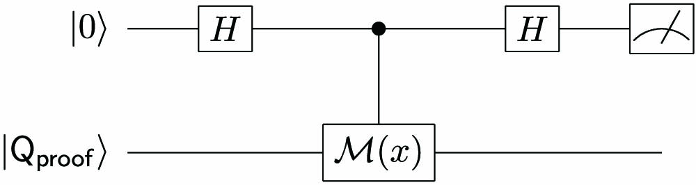
Figure 1.Core circuit. The circuit is similar to the swap test circuit and aims to check whether the input state is invariant under certain group multiplication. With a correct proof state, if
However, a malicious prover may send bogus proof states that deviate from Eq. (1) and give incorrect outcomes. Therefore, to ensure the soundness of the verification, the verifier has to do a property check on the received proof state, i.e., check that the state is invariant under the group multiplication for any , so that the elements in cannot be proven to be outside . In the original protocol, to verify the proof received is valid, the verifier needs to uniformly sample the subgroup elements in a reversible way and produce a quantum superposition of all the quantum labels,
In the new verification process for GNM, we reduce both the circuit depth and qubit number needed by importing the technique we call random state inspection (RSI). In RSI, the prover is required to send registers that carry copies of a state to the verifier. The verifier randomly selects one register to reserve and applies independent test channels to the other registers to check the property of the states that they carry. If all the registers pass the property checking, the verifier accepts the reserved register for the later verification process. Otherwise, the verifier rejects. We model the test channel as a quantum channel that maps an input register to an output qubit. The verifier measures the output qubit and regards outcome as pass and as fail. One can show that, if all the other registers have passed the test channels, the probability for the reserved register to fail passing the test channel (if tested) can be bounded to 0 at speed even when the registers are entangled. Denote the density operator of the reserved register and other registers as and , this bound can be written as
To show this bound, one just needs to analyze the density matrix of the output state after applying the test channels to all the registers. After testing all the other registers, the verifier can directly apply the later verification process on the reserved register as its property is ensured. By RSI, as the check and use of the proof state can be done in separate circuits, the circuit depth needed in the verification is reduced to that of the property checking or the later verification.
Besides reducing the circuit depth by RSI, we also simplify the property checking process in the original protocol. Rather than using the state in Eq. (2), which needs quantum group oracle calls to produce, we propose a simplified new process here. The test channel of the new process starts from sampling an element of the subgroup from a nearly uniform distribution with a classical computer by Babai’s algorithm [24]. Here, nearly uniform means the probability for to be any subgroup elements is in . The second step of the test channel is a core circuit. With the sampled element , an input state passes the test channel when . Therefore, in the whole verification process, all the quantum circuits the verifier needs to run are just core circuits with different group elements.
Here, we discuss the completeness and soundness of the new verification protocol. It can be proven that for any element and any quantum state , the probability of incorrectly proving the non-membership of , i.e., having , can be bounded as
To summarize, in our new protocol, we split the property checking of the proof state and the verification after property checking into different circuits by RSI. We also use a new property checking process that requires many fewer quantum resources. As a result, the verifier only needs to run a core circuit, which is shallow, for many times, rather than run a deep circuit with group operations. Also, the number of qubits that the verifier needs to keep is halved because the verifier no longer needs to keep a reversibly sampled quantum label.
3. EXPERIMENTAL SETUP AND RESULTS
In this work, an experimental demonstration of our new verification process is carried out. We consider an Abelian group . The four elements in are encoded in the polarization degree of freedom of photons as and , in which and denote the horizontal and vertical polarization of the photons, respectively. They can together span the whole two-qubit Hilbert space. The corresponding multiplication circuits of the four group elements are illustrated in the first line of Fig. 2(a), where the circuit of each element satisfies . We then construct the core circuits with these multiplications and map them to the optical interferometer illustrated in Fig. 2(a). For example, the circuit of transforms to , to , to , and to . The subgroups we choose are and . The quantum proof states for and used in the experiment are and respectively.
![]()
Figure 2.Circuit mapping and experimental setup. (a) The circuits for group multiplications in the first line are deduced from the quantum labels for the elements. They are used to construct the core circuits for the verification process in the second line. Optical paths are presented in the third line. Here, two BSs building an MZI are used to play the role of two Hadamard operations on the control qubit, which is realized with the path information. One path is regarded as
In our experiment, , and are put into the core circuit with right multiplication by , and . Our new protocol only requires one core circuit in each quantum circuit. In contrast, if one strictly follows the original protocol, at least five qubits are needed that contain two quantum labels of group elements and one ancillary qubit for reversible group element sampling. One also needs at least three group multiplications in the strict original circuit, whereas the new method only requires one multiplication in each circuit. The full experimental setup of the new protocol is shown in Fig. 2(b). The input states are generated by pumping two identically cut Type I beta-barium-borate (BBO) crystals whose optic axes are aligned in mutually perpendicular planes [26] with an ultraviolet (UV) source. The UV pulses are frequency doubled from a mode-locked Ti:sapphire laser centered at 800 nm with 130 fs pulse width and 76 MHz repetition rate. After compensating the birefringence effect between and in BBO crystals with quartz plates (QPs), maximally entangled photon pairs of the forms are produced [26]. Furthermore, by adjusting the polarization of pump pulses and downconversion photons, the other states of , , and are produced. The input photons are then sent to one of the quantum circuits in Fig. 2 to perform the core circuit with different group multiplications.
In our setup, the Mach–Zehnder interferometer (MZI) is realized by a Sagnac interferometer in which the path information of photons is regarded as the control qubit [27]. In a Sagnac interferometer, an optical nonpolarization beam splitter (BS), worked as the Hadamard gates on control qubit, is used to separate the beam into two paths, 1 and 2, which are treated as the control qubit and , respectively. Here, the BS is chosen to split 50:50 for 0° angle of incidence, which could decrease the difference of the split ratio of different polarizations. In the path , a half-wave plate (HWP) is used to implement CNOT gates set at 45° to reverse the photon polarization. The visibilities of two Sagnac interferometers are and , respectively. Note that, for the circuit E with Es multiplication, there is no CNOT gate and the HWP is set at 0°. Beams 1 and 2 combine in the BS and then are separated as beams 3 and 4. The polarization of photons is analyzed on the outputs of beams 3 and 4 by polarization beam splitters (PBSs), HWPs, and quarter-wave plates (QWPs). The photons are detected by single-photon detectors (D) equipped with 3 nm interference filters (IFs).
For the circuit , which implements the multiplication by , the probability of detecting equals the sum of the coincidence count (CC) of detectors located at and and the CC of detectors located at and , where is the output port 3 of the SI on the side of , and similarly hereinafter. The probability of detecting equals the sum of the CC of and and the CC of and . On the other hand, for the case of circuit , according to the corresponding mapping relation where the SI is only placed in the side, the probability of detecting equals the CC of and , and the probability of equals the CC of and . Similar methods suit the other circuits and .
Besides the interference visibility introduced above, two SIs are further verified with the input state of , which is prepared with a fidelity of . For the SI appearing in the circuit, the output state generated from the CC of and remains the maximally entangled state and is achieved experimentally with a fidelity of . For the other interferometer that is used in circuit , without inserting the CNOT gate, the output state generated from the CC of and is also the same as the input state and is achieved with a fidelity of . We further verify other output cases of the interferometers and achieve high fidelities for them. For the input state , we present the detailed experimental real matrix and imaginary matrix of the outputs here, as shown in Figs. 3 and 4.
![]()
Figure 3.Real parts of density matrices of the final output photons for the case with input state of
![]()
Figure 4.Imaginary parts of density matrices of the final output photons for the case with input state of
Equipped with the experiment setup, we first carried out our new process on the group . To demonstrate the test channel in our verification process, the correct proof as well as the bogus proofs and is produced and sent to the core circuit with multiplication by . A state passes the test if the control qubit is detected to be . The results are shown in Fig. 5(a). We find that the probabilities for a bogus proof to pass the state test do not exceed and have a significant gap toward the probability for a correct proof state to pass. Then we show how the nonmembership of an element can be verified with the correct proof state . The GNM of is verified when is detected in the core circuit with multiplication by . The experimental result is shown in Fig. 5(b). We find the probabilities for to be accepted are higher than for and lower than for . The above analysis implies that if the prover sends registers and the verifier chooses registers to test, the probability for a group of correct proof state to be accepted is greater than . In contrast, the probability for bogus state to pass the tests is only . For a general bogus proof, our theory can show that the probability for it to be accepted can be bounded by . Therefore, the gap is maximized when and the maximal value is 0.097.
![]()
Figure 5.Experimental results. (a), (c) Detecting probabilities of
For the other subgroup , the result is similar. The bogus proofs become , , , and the correct proof becomes . The probabilities for the bogus proofs to pass the test channel do not exceed and for the correct proof , the corresponding probability is , as shown in Fig. 5(c). We find that the probability for to be accepted when used for verifying GNM is higher than for and is lower than for , as shown in Fig. 5(d). In this case, is still bounded by and . The gap is maximized when and the maximal value is 0.207.
These completeness-soundness gaps strongly support the success of verification of GNM in the new protocol. Though the whole proof state contains more qubits, the number of qubits and operations in the circuit that the verifier needs to process at a time, which are more important to near-term devices, are greatly reduced.
4. CONCLUSION
In this work, we experimentally implement a verification process for GNM in an all-optical setup based on an ameliorative protocol in which the required quantum resources are greatly reduced. With multiplication of four group elements implemented by optical circuits, the process is accomplished on two subgroups consisting of two selected elements. As it is very likely that similar verification process of GNM can be used in other problems of finite groups, it will be interesting if this validity were formally proven and experimentally demonstrated. Furthermore, our novel verification process is helpful to construct more quantum protocols, which could be practical for near-term quantum devices.
References
[1] P. W. Shor. Algorithms for quantum computation: discrete logarithms and factoring. 35th Annual Symposium on Foundations of Computer Science, 124-134(1994).
[2] A. M. Childs, R. Cleve, E. Deotto, E. Farhi, S. Gutmann, D. A. Spielman. Exponential algorithmic speedup by a quantum walk. 35th Annual ACM Symposium on Theory of Computing, 59-68(2003).
[3] M. A. Nielsen, I. Chuang. Quantum Computation and Quantum Information(2002).
[4] S. Goldwasser, S. Micali, C. Rackoff. The knowledge complexity of interactive proof systems. SIAM J. Comput., 18, 186-208(1989).
[5] J. Watrous. PSPACE has constant-round quantum interactive proof systems. Theor. Comput. Sci., 292, 575-588(2003).
[6] F. Centrone, N. Kumar, E. Diamanti, I. Kerenidis. Experimental demonstration of quantum advantage for NP verification with limited information. Nat. Commun., 12, 850(2021).
[7] A. Broadbent, J. Fitzsimons, E. Kashefi. Universal blind quantum computation. 50th Annual IEEE Symposium on Foundations of Computer Science, 517-526(2009).
[8] J. F. Fitzsimons, E. Kashefi. Unconditionally verifiable blind quantum computation. Phys. Rev. A, 96, 012303(2017).
[9] S. Barz, J. F. Fitzsimons, E. Kashefi, P. Walther. Experimental verification of quantum computation. Nat. Phys., 9, 727-731(2013).
[10] A. Broadbent, Z. Ji, F. Song, J. Watrous. Zero-knowledge proof systems for QMA. IEEE 57th Annual Symposium on Foundations of Computer Science (FOCS), 31-40(2016).
[11] A. B. Grilo, W. Slofstra, H. Yuen. Perfect zero knowledge for quantum multiprover interactive proofs. IEEE 60th Annual Symposium on Foundations of Computer Science (FOCS), 611-635(2019).
[12] Z. Ji, A. Natarajan, T. Vidick, J. Wright, H. Yuen. MIP*= RE(2020).
[13] A. Natarajan, J. Wright. NEEXP is contained in MIP. IEEE 60th Annual Symposium on Foundations of Computer Science (FOCS), 510-518(2019).
[14] M. Sipser. Introduction to the theory of computation. ACM SIGACT News, 27, 27-29(1996).
[15] A. Y. Kitaev, A. Shen, M. N. Vyalyi. Classical and Quantum Computation(2002).
[16] J. Watrous. Quantum computational complexity(2008).
[17] D. Aharonov, T. Naveh. Quantum NP - a survey(2002).
[18] H. Kobayashi, K. Matsumoto, T. Yamakami. Quantum Merlin-Arthur proof systems: are multiple Merlins more helpful to Arthur?. Algorithms and Computation, 189-198(2003).
[19] L. Babai. Trading group theory for randomness. 7th Annual ACM Symposium on Theory of Computing, 421-429(1985).
[20] L. Babai. Bounded round interactive proofs in finite groups. SIAM J. Discrete Math., 5, 88-111(1992).
[21] J. Watrous. Succinct quantum proofs for properties of finite groups. 41st Annual Symposium on Foundations of Computer Science, 537-546(2000).
[22] J. Preskill. Quantum computing in the NISQ era and beyond. Quantum, 2, 79(2018).
[23] F. Arute, K. Arya, R. Babbush, D. Bacon, J. C. Bardin, R. Barends, R. Biswas, S. Boixo, F. G. S. L. Brandao, D. A. Buell, B. Burkett, Y. Chen, Z. Chen, B. Chiaro, R. Collins, W. Courtney, A. Dunsworth, E. Farhi, B. Foxen, A. Fowler, C. Gidney, M. Giustina, R. Graff, K. Guerin, S. Habegger, M. P. Harrigan, M. J. Hartmann, A. Ho, M. Hoffmann, T. Huang, T. S. Humble, S. V. Isakov, E. Jeffrey, Z. Jiang, D. Kafri, K. Kechedzhi, J. Kelly, P. V. Klimov, S. Knysh, A. Korotkov, F. Kostritsa, D. Landhuis, M. Lindmark, E. Lucero, D. Lyakh, S. Mandrà, J. R. McClean, M. McEwen, A. Megrant, X. Mi, K. Michielsen, M. Mohseni, J. Mutus, O. Naaman, M. Neeley, C. Neill, M. Y. Niu, E. Ostby, A. Petukhov, J. C. Platt, C. Quintana, E. G. Rieffel, P. Roushan, N. C. Rubin, D. Sank, K. J. Satzinger, V. Smelyanskiy, K. J. Sung, M. D. Trevithick, A. Vainsencher, B. Villalonga, T. White, Z. J. Yao, P. Yeh, A. Zalcman, H. Neven, J. M. Martinis. Quantum supremacy using a programmable superconducting processor. Nature, 574, 505-510(2019).
[24] L. Babai. Local expansion of vertex-transitive graphs and random generation in finite groups. 23rd Annual ACM Symposium on Theory of Computing, 164-174(1991).
[25] L. Babai, E. Szemerédi. On the complexity of matrix group problems I. 25th Annual Symposium on Foundations of Computer Science, 229-240(1984).
[26] P. G. Kwiat, E. Waks, A. G. White, I. Appelbaum, P. H. Eberhard. Ultrabright source of polarization-entangled photons. Phys. Rev. A, 60, R773-R776(1999).
[27] K. Sun, X.-J. Ye, Y. Xiao, X.-Y. Xu, Y.-C. Wu, J.-S. Xu, J.-L. Chen, C.-F. Li, G.-C. Guo. Demonstration of Einstein-Podolsky-Rosen steering with enhanced subchannel discrimination. Npj Quantum Inf., 4, 12(2018).

Set citation alerts for the article
Please enter your email address
© Copyright 2018-2021 | Chinese Laser Press. All Rights Reserved 沪ICP备15018463号-20