Polarization holography has attracted much attention in recent research. Many studies on polarization gratings have been carried out. The research group led by Prof. Changshun Wang from Shanghai Jiao Tong University designs an all-optical logic sequence generator, which has one input port and four output ports, based on two different polarization holographic gratings. The logic signals of output ports depend entirely on the polarization of the input light signal. This work has been published in Chinese Optics Letters, Volume 17, Issue 8, 2019 (Renjie Xia, Changshun Wang, Tianyu Chen, Yujia Pan, Ziyao Lü, Lili Sun. Design of an all-optical logic sequence generator based on polarization holographic gratings.).
The all-optical logic sequence generator can produce four kinds of logic sequence output signals: 1000, 0100, 0010, and 0001, corresponding to the input light signal of four different polarization states: the p-linear, s-linear, left-handed circular, and right-handed circular. There is no need for additional electronic control in this logic sequence generator, so it is very thin and can be easily integrated into various optical systems requiring optical signal control, such as optical path switching in optical communication system. The all-optical logic sequence generator is shown in Fig. 1.
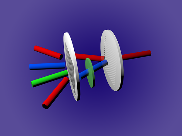
Fig. 1. Schematic of all-optical logic sequence generator. DW1 and DW2 are two different kinds of polarization holographic gratings. QWP is the quarter-wave plate. B1 and B2 represent the -1 and +1 order diffraction light of DW1, respectively.
When the incident light is p-linearly polarized, the diffraction light signals can be detected in the directions of 2, 3 and 4. When the incident light is s-linearly polarized, the diffraction light signals can be detected in the directions of 1, 3 and 4. As for the left-handed circularly polarized incident light, the diffraction light signals can be detected in the directions of 1, 2 and 4. If the incident light is right-handed circularly polarized, the diffraction light signals can be detected in the directions of 1, 2 and 3. If the signal of port denote logic state 0, no signal denote logic state 1, the logic sequence table can be obtained. The output of p-linearly polarized incident light is logic sequence signal 1000, the output of s-linearly polarized incident light is logic sequence signal 0100, the output of left-handed circularly polarized incident light is logic sequence signal 0010, and the output of right-handed circularly polarized incident light is logic sequence signal 0001.
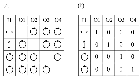
Fig. 2. (a) The diagram of the incident light signal of different polarization states and corresponding output light signals. (b) The logic sequence table. Column I1 represents four different polarizations of the incident light; columns O1, O2, O3 and O4 represent the diffraction light in four directions respectively, corresponding to the yellow, green, blue and red cylinders in Fig. 1. Signal of port denotes logic state 0, no signal denotes logic state 1.
In this work, an all-optical logic sequence generator based on two different polarization holographic gratings is designed. The polarization states of the input signal light are controlled to produce four different logic sequence signals and the working principle of the logic sequence generator is analyzed. This logic sequence generator has many potential applications, such as optical path switching in optical communication system. The structure is very thin so it can be easily integrated into various optical systems requiring optical signal control. The research group hopes to integrate the structure into some complex optical communication systems to test its actual effect in the future, and they believe it can make a good function in the further applications.