• High Power Laser Science and Engineering
  • Vol. 8, Issue 4, 04000e37 (2020)
Hao Yang1、2, Jian Cheng1、*, Zhichao Liu2, Qi Liu1, Linjie Zhao1, Chao Tan1, Jian Wang2, and Mingjun Chen1、*
Author Affiliations
  • 1State Key Laboratory of Robotics and System, Harbin Institute of Technology, Harbin150001, China
  • 2Research Center of Laser Fusion, China Academy of Engineering Physics, Mianyang621900, China
  • show less
    DOI: 10.1017/hpl.2020.37 Cite this Article Set citation alerts
    Hao Yang, Jian Cheng, Zhichao Liu, Qi Liu, Linjie Zhao, Chao Tan, Jian Wang, Mingjun Chen. Potential damage threats to downstream optics caused by Gaussian mitigation pits on rear KDP surface[J]. High Power Laser Science and Engineering, 2020, 8(4): 04000e37 Copy Citation Text show less
    The effect of the Gaussian mitigation pit on the far-field propagation of the outgoing laser. (a) Sketch of the far-field modulation caused by the Gaussian mitigation contour on a KDP rear surface. (b) The relative positions of two dominant downstream light intensification patterns caused by the Gaussian mitigation pit on a KDP rear surface. Dhs and Drz refer to the focal lengths of on-axis hot spot and off-axis ring caustic, respectively.
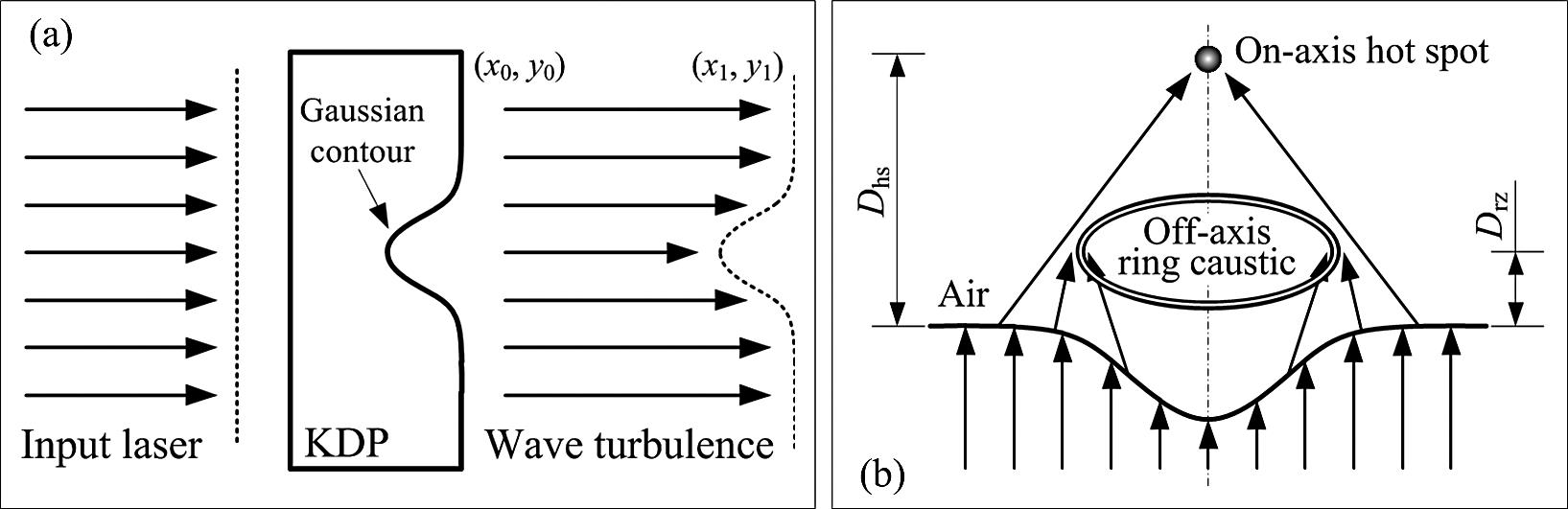
    Fig. 1. The effect of the Gaussian mitigation pit on the far-field propagation of the outgoing laser. (a) Sketch of the far-field modulation caused by the Gaussian mitigation contour on a KDP rear surface. (b) The relative positions of two dominant downstream light intensification patterns caused by the Gaussian mitigation pit on a KDP rear surface. Dhs and Drz refer to the focal lengths of on-axis hot spot and off-axis ring caustic, respectively.
    Laser damage test of a downstream fused silica component induced by a Gaussian mitigation pit on the KDP rear surface. (a) Optical path diagram of the laser damage experiment for downstream fused silica components. (b) Schematic of laser irradiation to a Gaussian mitigation pit on the rear surface of a KDP crystal.
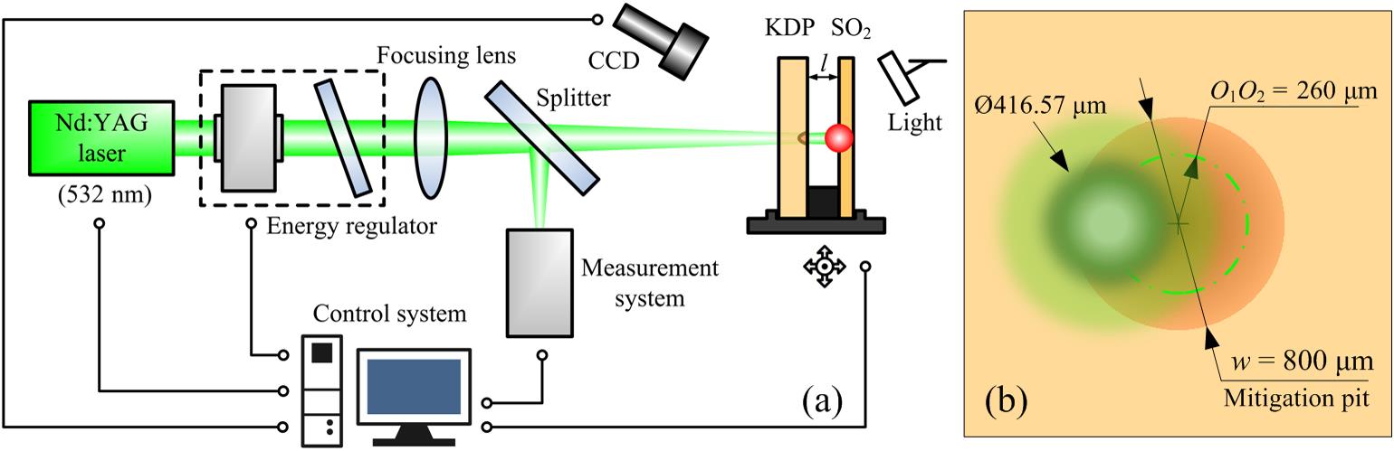
    Fig. 2. Laser damage test of a downstream fused silica component induced by a Gaussian mitigation pit on the KDP rear surface. (a) Optical path diagram of the laser damage experiment for downstream fused silica components. (b) Schematic of laser irradiation to a Gaussian mitigation pit on the rear surface of a KDP crystal.
    The far-field diffraction patterns caused by the Gaussian mitigation contour with a width of 800 μm and a depth of 10 μm at downstream distance of (a) Z = 10 mm; (b) Z = 20 mm; (c) Z = 30 mm; (d) Z = 50 mm; (e) Z = 70 mm; (f) Z = 90 mm.
    Fig. 3. The far-field diffraction patterns caused by the Gaussian mitigation contour with a width of 800 μm and a depth of 10 μm at downstream distance of (a) Z = 10 mm; (b) Z = 20 mm; (c) Z = 30 mm; (d) Z = 50 mm; (e) Z = 70 mm; (f) Z = 90 mm.
    Comparison of the downstream light-field modulations between the Gaussian mitigation pits on KDP crystal and fused silica.
    Fig. 4. Comparison of the downstream light-field modulations between the Gaussian mitigation pits on KDP crystal and fused silica.
    Microscopic morphology of laser damage and Gaussian mitigation profile. (a) SEM image of a laser damage site on the surface of a KDP crystal. (b) Optical micrograph of a KDP surface with a Gaussian mitigation pit. The inset is the three-dimensional shape of the Gaussian mitigation pit with a width of 800 μm and a depth of 10 μm. (c) Two-dimensional profile of the Gaussian mitigation pit and the damage site. The first inset is the local enhanced image. The second inset shows the edge profile of the mitigated KDP contour and the mitigated fused silica contour.
    Fig. 5. Microscopic morphology of laser damage and Gaussian mitigation profile. (a) SEM image of a laser damage site on the surface of a KDP crystal. (b) Optical micrograph of a KDP surface with a Gaussian mitigation pit. The inset is the three-dimensional shape of the Gaussian mitigation pit with a width of 800 μm and a depth of 10 μm. (c) Two-dimensional profile of the Gaussian mitigation pit and the damage site. The first inset is the local enhanced image. The second inset shows the edge profile of the mitigated KDP contour and the mitigated fused silica contour.
    LIDTs for the Gaussian mitigation pit on (a) the KDP rear surface and (b) the front surface of fused silica.
    Fig. 6. LIDTs for the Gaussian mitigation pit on (a) the KDP rear surface and (b) the front surface of fused silica.
    Comparison of the downstream light-field modulations caused by a Gaussian mitigation pit on the KDP rear surface with irradiation by flat-top laser and Gaussian laser. (a) Simulation schematic of light propagation when the KDP rear surface with mitigation pit is irradiated by incident laser. (b) Comparison of the light-field modulation generated by the flat-top laser and the Gaussian laser at a position 10 mm downstream. The inset is a diffraction pattern produced by a Gaussian laser at a position 10 mm downstream away from the crystal surface with a mitigation pit when the center point distance O1O2 is 260 mm.
    Fig. 7. Comparison of the downstream light-field modulations caused by a Gaussian mitigation pit on the KDP rear surface with irradiation by flat-top laser and Gaussian laser. (a) Simulation schematic of light propagation when the KDP rear surface with mitigation pit is irradiated by incident laser. (b) Comparison of the light-field modulation generated by the flat-top laser and the Gaussian laser at a position 10 mm downstream. The inset is a diffraction pattern produced by a Gaussian laser at a position 10 mm downstream away from the crystal surface with a mitigation pit when the center point distance O1O2 is 260 mm.
    Microscopic morphology of the laser damage sites on downstream fused silica surface observed by SEM. (a) Pansy damage site; (b) mussel damage sites.
    Fig. 8. Microscopic morphology of the laser damage sites on downstream fused silica surface observed by SEM. (a) Pansy damage site; (b) mussel damage sites.
    Comparison between the calculations and experiments. (a) Two-dimensional distribution of downstream light-field modulation along the laser propagation (z-axis) caused by the Gaussian mitigation pit on the rear surface of a KDP crystal. (b) Optical micrograph of laser damage morphology on downstream fused silica components.
    Fig. 9. Comparison between the calculations and experiments. (a) Two-dimensional distribution of downstream light-field modulation along the laser propagation (z-axis) caused by the Gaussian mitigation pit on the rear surface of a KDP crystal. (b) Optical micrograph of laser damage morphology on downstream fused silica components.
    Hao Yang, Jian Cheng, Zhichao Liu, Qi Liu, Linjie Zhao, Chao Tan, Jian Wang, Mingjun Chen. Potential damage threats to downstream optics caused by Gaussian mitigation pits on rear KDP surface[J]. High Power Laser Science and Engineering, 2020, 8(4): 04000e37
    Download Citation