
Longbin LI, Yudong XUE, Jianbao HU, Jinshan YANG, Xiangyu ZHANG, Shaoming DONG. Influence of SiC Nanowires on the Damage Evolution of SiCf/SiC Composites [J]. Journal of Inorganic Materials, 2021, 36(10): 1111
- Journal of Inorganic Materials
- Vol. 36, Issue 10, 1111 (2021)
Abstract
Among various types of continuous fibre reinforced ceramic matrix composites (CMCs), SiC fiber (SiCf)-reinforced SiC matrix composites (SiCf/SiC) with superior mechanical and thermal properties have obtained increasing attention in industrial applications like aerospace, nuclear and braking system over past few decades[
However, research on the mechanism of toughening and strengthening of SiCnw is still not rich enough to elaborate the effect on mechanical behavior of hierarchical composites under external load. According to previous study[
1 Experimental
1.1 Preparation of materials
SiCnw were in situ grown on SiC fiber (KD-II, with 500 nm thick BN interphase deposition in advance) surface after 10 h Ni2+ solution treatment by chemical vapor infiltration (CVI). H2 (30 sccm) and methyl trichlorosilane (MTS, 100 sccm) were utilized as reductant as well as source gas. The growth of SiCnw was carried out under a pressure of 2 kPa at 1000 ℃ for 1 h. To achieve the optimum of SiCnw/matrix interfacial bonding, BN interphase was deposited on SiCnw surface via chemical vapor deposition (CVD) method at 800 ℃ using BCl3 (10 sccm) and NH3 (20 sccm).The composites were densified using precursor impregnation and pyrolysis (PIP) method. Finally, original SiCf/SiC composites, as-grown and BN-coated SiCnw modified SiCf/SiC hierarchical composites were fabricated. These composites were marked as SiCf/SiC, SiCf/SiC-SiCnw and SiCf/SiC-SiCnw/BN, respectively.
1.2 Characterizations
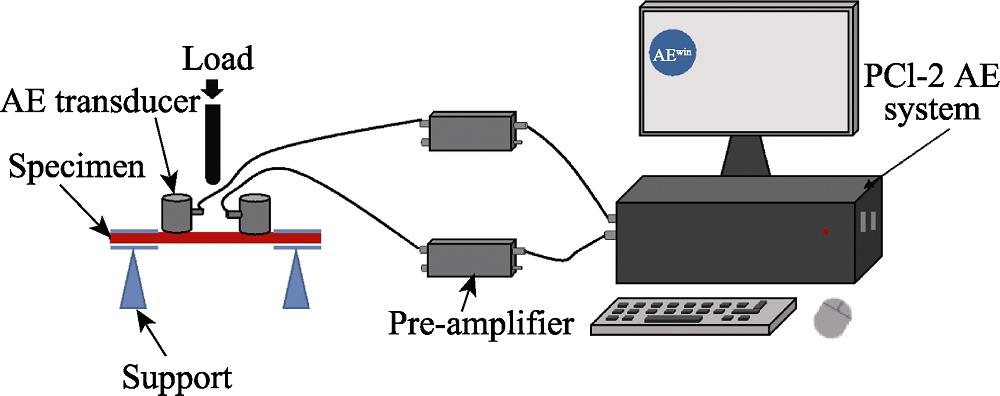
The bulk density and open porosity were evaluated by the Archimedes principle. Three-point bending test was performed on a CRIMS-DDl20 universal testing machine with a span of 30 mm at a cross head speed of 0.1 mm/min. Composites were cut into bar specimens with the dimension of 2.0 mm×4.0 mm×40 mm for bending test. AE technique was employed to detect in situ information of damage process in composites during the three-point bending test. AE activity, containing the information of damage events, was real-timely recorded. AE detection was conducted by using a two-channel MISTRAS acquisition system (Physical Acoustics Corporation) with a sampling rate of 2 MHz. Two nano-30 (Physical Acoustics Corporation) sensors were mounted on the surface of specimens to record AE signals. Two pre-amplifiers were also adopted and set with the pre-amplification of 40 dB and band-pass filtering of 20-1200 kHz. To avoid possible noise recording, the threshold was set at 45 dB (as shown in Fig. 1). Hitachi SU8220 field-emission scanning electron microscope (SEM) were used to characterize the morphology and microstructure of as-grown and BN-coated BNNTs. The fracture morphology of fibers in composites were also investigated via SEM. The Vickers Hardness Impresses was applied to induce the crack formation of SiCnw/SiC matrix by a Vickers hardness tester (HVS-5) with a load of 500 g for 10 s, and the crack propagation was observed by SEM.
![]()
Figure .Schematic figure of three-point test with
2 Results and discussion
2.1 Microstructure
The morphologies of fibers covered by SiCnw before matrix infiltration are shown in Fig. 2. As seen in Fig. 2(a-c), the microscale network composed of SiCnw filled the gap between fiber bundles which surfaces are barely exposed. The length of nanowires as secondary reinforcement is approximately 10-20 μm and the diameter is about 60-100 nm. Macroscopic properties like density and porosity for each group are listed in Table 1. Compared to original SiCf/SiC, the density of composite SiCf/SiC-SiCnw increases from 1.98 g/cm3 to 2.08 g/cm3, and the open porosity decreases from 17.64% to 11.58%. Combined with Fig. 1(d, e) demonstrating the pores in fiber bundles, it indicates that the incorporation of SiCnw densifies the monolithic composite by suppressing the formation of large-sized micro-pores. ZHAO et al.[
![]()
Figure .Typical SEM images of (a, b) as-grown SiCnw, (c) BN-coated SiCnw, and typical SEM images demonstrating the pore size of (d) SiCf/SiC and (e) SiCf/SiC-SiCnw composites
| Composite | SiCf/SiC | SiCf/SiC-
| SiCf/
|
|---|---|---|---|
| Bulk density/(g·cm-3) | (1.98±0.03) | (2.02±0.04) | (2.08±0.03) |
| Open porosity/% | (17.64±1.08) | (14.39±0.60) | (11.58±1.35) |
Table 1.
Density and porosity of different composites
The aim of deposition of BN interphase on SiCnw is to render composites more optimized mechanical strength, since the direct contact between SiC nanowires and matrix leads to an undesirable strong bond[
2.2 Mechanical properties and fracture morphologies of composites
Mechanical properties of these composites are evaluated and gathered in Table 2. It can be implied that SiCnw as secondary reinforcement indeed produce positive influence on mechanical behavior. Flexural strength of SiCf/SiC-SiCnw and SiCf/SiC-SiCnw/BN is 15.7% and 42.1% higher than that of original SiCf/SiC, respectively, which may be attributed to the strengthening effect of nanowires in and between fiber bundles, as shown in Fig. 2. This impact is further intensified by deposition of BN interphase on the surface of nanowires. The fracture morphologies of each group are shown in Fig. 3 and Fig. 4. As discussed above, direct contact of nanowires with matrix causes a strong interfacial bond. It can be confirmed by the observation in Fig. 3(a) that few pull-outs of nanowires are found. Instead of tending to be pulled out, nanowires prefer to breaking. On the contrary, obviously much more pull-outs are inspected in composites SiCf/SiC-SiCnw/BN, as illustrated in Fig. 3(b). Furthermore, a local part of Fig. 3(b) is magnified in Fig. 3(c), indicating that nanowires are easier to be pulled out with assistance of weaker interfacial bonding. Fig. 4 demonstrates different fracture morphologies of fibers in three types of composites. It can be concluded that fiber/matrix interfacial bonding is exceedingly enhanced after introducing SiCnw, for the SiCf/SiC-SiCnw shows apparent brittle fracture mode in Fig. 4(a). However, above mentioned effect is effectively alleviated by introducing BN interphase, phenomenon of long pull-outs of fibers happens again in SiCf/SiC-SiCnw/BN, indicating better mechanical performance for material after the formation of obvious transverse cracks[
| Composite | SiCnw content /
| Flexural strength,
| Proportional limit
| Strain at flexural
| First AE stress,
| AE onset stress,
|
|---|---|---|---|---|---|---|
| SiCf/SiC | 0 | (356.7±16.2) | (153.9±6.4) | (0.39±0.05) | (58.8±7.5) | (116.1±8.9) |
| SiCf/SiC-SiCnw | 2.0 | (412.6±22.4) | (185.1±7.7) | (0.63±0.06) | (66.1±6.2) | (155.8±7.7) |
| SiCf/SiC-SiCnw/BN | 2.0 | (506.4±28.3) | (247.7±8.6) | (0.88±0.12) | (78.5±5.2) | (171.6±15.9) |
Table 2.
Properties of original composites, as-grown and BN-coated hierarchical composites
![]()
Figure .SEM fractural morphologies of (a) as-grown SiCnw, (b, c) BN-coated SiCnw in composites Local parts marked by white rectangular borders demonstrating that SiCnw tends to break (a) or pull out (b, c)
![]()
Figure .Fracture morphologies of composite (a) SiCf/SiC, (b) SiCf/SiC-SiCnw and (c) SiCf/SiC-SiCnw/BN The images demonstrating the pull-out length of fibers
It is noticeable that the strain at maximum load for composites SiCf/SiC-SiCnw is relatively bigger than that for original SiCf/SiC, a possible explanation could be illustrated as following. In general, the failure strain of composites is mainly decided by fiber/matrix bond and stress status in fibers. The SiCnw/matrix strong bond may help load transfer among fibers, and improve their ability to bear load. Therefore, load concentration of fibers is reduced and break of fibers is delayed, causing bigger failure strain in composites SiCf/SiC-SiCnw. However, stronger evidence requires more profound study.
As inspiration of this research, the restriction effect of nanowires on the formation and evolution of matrix cracks was observed and significantly benefits fracture behavior of materials owing to an increase of cracks propagation path and extra energy dissipation[
2.3 AE diagrams and damage mechanisms
To get further understanding of the impact of SiCnw on damage evolution of composites, AE measurement was performed in the three-point bending tests. The AE events with corresponding energy and numbers was detected and recorded, reflecting damage evolution such as generation and propagation of cracks. On basis of AE energy information, normalized cumulative AE energy versus stress curve are plotted to clarify damage threshold stress. Normalization is determined by the total energy of all AE events as denominator for every cumulative AE energy in specific stress. The slope of curve represents damage process rate[
![]()
Figure .Representative normalized cumulative AE energy curves as a function of stress (a) for composite SiCf/SiC (orange), SiCf/SiC-SiCnw (black) and SiCf/SiC-SiCnw/BN (blue)
![]()
Figure .Typical stress-strain curves of SiCf/SiC(orange), SiCf/SiC-SiCnw (black) and SiCf/SiC-SiCnw/BN (blue)
The effect of SiCnw can also be confirmed by stress- strain curves in Fig. 5. As is well-known, with external stress increasing, the traditional fracture mode of composites could be illustrated as following[
Above analyses hint that early damage evolution is delayed, i.e., the required stress for the formation of microcracks or transverse cracks is lifted by introducing SiC nanowires, and the restriction effect is more notable with the assistance of BN interphase. For confirming the assumption, the scattering diagram of individual AE events over time is demonstrated in Fig. 7. As is shown, the first detected AE activity is delayed in composites SiCf/SiC-SiCnw and SiCf/SiC-SiCnw/BN as anticipated, yet the obvious increase of AE activity representing the formation of apparent transverse crack does not show the same trend by comparison. With the aim of explaining the contradiction, Vickers Hardness test were performed to obtain information about crack propagation in composites. As shown in Fig. 8, after tests of same parameters, crack deflection and bridging are clearly observed in composites SiCf/SiC, inferring that the cumulative fracture energy has been consumed and the seriously damaged matrix is brittle. By comparison, there are much less cracks caused by the indentation in composites SiCf/SiC-SiCnw and SiCf/SiC-SiCnw/BN, the latter even obtain few cracks after the test, indicating that the fracture energy is far from enough for the formation of obvious cracks and subsequent propagation.
![]()
Figure .Scatter diagrams of the energy of individual AE events as a function of time in composites (a) SiCf/SiC, (b) SiCf/SiC-SiCnw, and (c) SiCf/SiC-SiCnw/BN
![]()
Figure .SEM micrographs of crack propagation around the indentation in composites (a) SiCf/SiC; (b) SiCf/SiC-SiCnw; (c) SiCf/SiC-SiCnw/BN
Considering observation given above, the inconsistence of previous assumption with AE scattering diagrams might be explained as following. In composites SiCf/SiC and SiCf/SiC-SiCnw/BN, cracks tend to deflect along the weak-bonded BN interphase between fiber/matrix or nanowire/matrix, while in composites SiCf/SiC-SiCnw, cracks are more likely to be suppressed owing to the strong bonding between nanowires/matrix. In composite SiCf/SiC, the propagation of cracks in brittle matrix is considerably fast, resulting in earlier presence of both the first recorded AE events and high-energy AE events, as confirmed in Fig. 7(a). On the other hand, as shown in Fig. 8(b, c), SiCnw can effectively decrease the size of cracks by bridging between cracks, causing the improvement of $\sigma_{min}$ and $\sigma_{onset}$ in Fig. 5(b). In composites SiCf/SiC-SiCnw, nanowires tend to break as external stress increases, which brings forward the evident increase of AE activities. By contrast, due to the weak BN interphase in favor of sliding and pull-outs of nanowires, there are much more AE events recorded in composites SiCf/SiC-SiCnw/BN. The presence of rapid increase of AE activities is postponed, and the high-energy period lasts for a shorter time. It is also noteworthy that AE events gain an obvious boost after the hysteresis at early stage of damage evolution, which may result from the merging of microcracks or the breaking of short nanowires.
3 Conclusions
SiC nanowires were introduced in composite SiCf/SiC to realize a hierarchical structure. The modification effect of nanowires on microstructure and mechanical properties was investigated. Compared to original SiCf/SiC, the density and porosity of SiCf/SiC-SiCnw and SiCf/SiC-SiCnw/BN are both positively optimized to a higher level. SiC nanowires wrapped by BN interphase significantly improve the fractural strength and proportional limit. AE results show that the proportional limit may correlates with onset stress of composites. With the assistance of Vickers Hardness Impresses, it is found that the reinforcing effect of SiCnw may be attributed to delaying the presence of microcracks and bridging cracks. In addition, the resultant hindering effect of cracks of SiCnw could not be fully optimized when SiCnw are not coated with BN, although the brittle matrix is effectively enhanced. Thus, the strength of SiCf/SiC-SiCnw is comparable to original composites SiCf/SiC.
Supporting materials:
The supproting materials related to this article refer to
References
[2] A DICARLO J, M van ROODE. Ceramic Composite Development for Gas Turbine Engine Hot Section Components. Barcelona, Spain, 221-231(2006).
[11] R DONG, W YANG, P WU et al. Effect of reinforcement shape on the stress-strain behavior of aluminum reinforced with SiC nanowire. Materials & Design, 88, 1015-1020(2015).
[18] S ARGON A. Fracture of composites. Treatise on Materials Science and Technology, 1, 79-114(1972).

Set citation alerts for the article
Please enter your email address
© Copyright 2018-2021 | Chinese Laser Press. All Rights Reserved 沪ICP备15018463号-20