
Weijie Ren, Jianfeng Sun, Peipei Hou, Ronglei Han, Hongyu He, Haisheng Cong, Chaoyang Li, Longkun Zhang, Yuxin Jiang. Direct phase control method for binary phase-shift keying space coherent laser communication[J]. Chinese Optics Letters, 2022, 20(6): 060601
- Chinese Optics Letters
- Vol. 20, Issue 6, 060601 (2022)
Abstract
Keywords
1. Introduction
Space laser communication has unique advantages: large bandwidth, license-free spectrum, high data rate, easy and quick deployability, less power, and low requirements[
Compared with the direct detection receiver, the most significant advantage of coherent reception is the improvement in sensitivity owing to the amplification of the local oscillator light[
Digital coherent reception requires analog-to-digital converters (ADCs) with a sampling rate greater than or equal to twice the communication rate, which is challenging for ADCs and digital signal processing (DSP)[
Sign up for Chinese Optics Letters TOC. Get the latest issue of Chinese Optics Letters delivered right to you!Sign up now
In this Letter, the direct phase control phase locking method based on in-phase and quadrature (IQ) modulation is presented, and the corresponding experimental scheme and matching phase-locked algorithm verify its feasibility. The direct phase control method can be used not only for space communications, but also as a complementary solution for outdoor fiber optic networks and indoor data center applications[
2. Theoretical Model
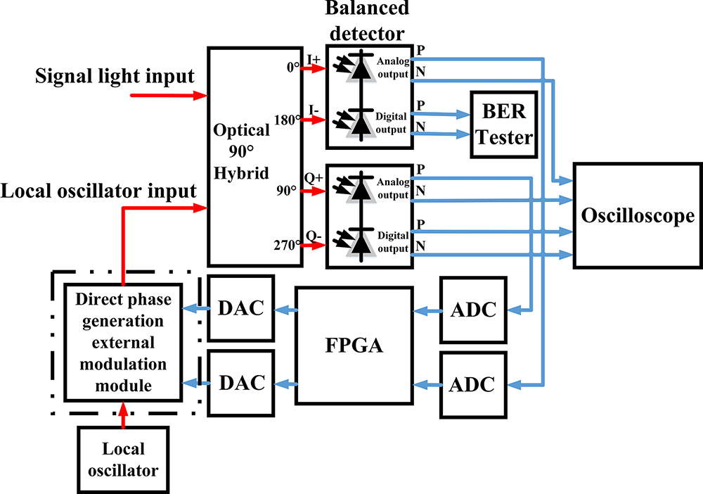
Figure 1 shows the structure of the BPSK homodyne coherent receiver based on the direct phase control method. The optical 90° hybrid combines the received signal laser with the local laser and outputs four-channel mixing light. The two in-phase light channels enter into the first balanced detector, and the two quadrature light channels enter into the second balanced detector. The output voltages of the I-arm and Q-arm are expressed as
![]()
Figure 1.Schematic of the experimental device for direct phase control method.
The two analog signals, and , were sampled and quantized synchronously by the two ADCs, and the two digitized signals were used to calculate the carrier phase difference between the signal light and the local oscillator light. They are expressed as
The direct change in the local oscillator light phase depends on the cooperation between the control electrical signal and the direct phase generation external modulation module, as shown in Fig. 2. When the IQ bias controller is working normally, two orthogonal control signals are added to the radio frequency (RF) input of the IQ modulator. If the expression of the module input light is , where is the input optical power, is the angular frequency of input light, and represents the initial phase of input light, the output light of the module can be expressed as
![]()
Figure 2.Specific structure diagram of direct phase generation external modulation module.
The correctness of Eq. (8) depends on the IQ bias controller to control the IQ modulator at the direct-current bias point when realizing quadrature phase-shift keying (QPSK). Equation (8) shows that the phase change of the local oscillator light can be realized by directly changing the RF signal phase. This is the physical basis for realizing the direct phase control method; is the foundation of phase locking in this method.
The frequency difference between the signal light and the local oscillator light should meet the following condition: , where is the output sampling rate of the two digital-to-analog converters (DACs); can be obtained in real time by performing a fast Fourier transform (FFT) on . When the direct phase control method starts, the analog signal output by the two DACs can be expressed as
The latter phase difference must be obtained at least after the previous phase difference calculation is completed, and then is performed. When the FPGA obtains N values of the phase difference, the analog signals output by the two DACs are expressed as
In a traditional OPLL system, the voltage-controlled oscillator is a voltage–frequency conversion device, which means that the carrier phase-locking depends on the change of the control signal frequency. However, the realization of phase-locking does not necessarily depend on the changing frequency. Direct phase compensation can also achieve carrier phase-locking. This method is to complete phase lock by applying an accumulated phase change to the electrical control signal. Owing to the existence of the loop delay, linear phase compensation is also required, which is reflected in Eq. (13).
3. Results and Discussion
In this experimental verification, the sampling rates of both ADCs were 1 GHz; ; ; ; ; ; and . Therefore, it is equivalent to applying a direct phase control operation every 880 ns and linear phase compensation every 7040 ns. The existence of loop delay is a prerequisite for linear phase compensation.
In our experiments, the ADC model is EV10AQ190A (Teledyne e2v, UK). The DAC model is AD9747 (Analog Devices, US). The series of the FPGA is XC7K325TFFG900-2 (Xilinx, US). The IQ modulator model is FTM7962EP (FUJITSU, JPN). The IQ bias controller model is MBC-IQ-03(plugtech, CHN). The electrical amplifier model is OA3MHQM (Centellax, US). The balanced detector model is LB-BPD10G (SDFSO, CHN). The other experimental parameters used for this verification are listed in Table 1.
| Parameter | Symbol | Value |
|---|---|---|
| Laser wavelength | 1554.94 nm | |
| Received signal power | PS | −45 to −33 dBm |
| Communication rate | Rb | 2.5 Gbit/s |
| Line width (TX/RX) | 5000 Hz | |
| Responsivity | R | 0.75 A/W |
| Power-splitting ratio | kS | 0.5 |
Table 1. Experimental Parameters
Within a period of time before and after the start of the direct phase-locking method, the change curve of double phase difference is shown in Fig. 3. The details inside the two dashed boxes in Fig. 3 are shown in Fig. 4. It can be seen from Fig. 4(a) that before the direct phase control method starts, the signal laser frequency is greater than the local laser frequency, which is 4.763 MHz. The FPGA begins to compensate the frequency difference at and begins to calculate the average value of the eight phases at . The DACs perform direct phase control operations after 530 ns. After 880 ns, they obtain new phase values and continue to carry out phase compensation. It can be considered that the loop acquisition time is approximately 530 ns, from the beginning of applying the direct phase control method to the completion of the phase-locking, and the phase-locking can be completed directly without cycle skipping. Next, the direct phase compensation and linear phase compensation operations will continue, as described in Eq. (13). As can be calculated from Fig. 4(b), the standard deviation of the phase-locked error is 5.2805°. The eye diagram of demodulated signal is shown in Fig. 5.
![]()
Figure 3.Double phase difference curve before and after direct phase control method.
![]()
Figure 4.Partial image of double phase difference curve in Fig.
![]()
Figure 5.Eye diagram of 2.5 Gbit/s baseband signal after phase locking.
In the coherent communication experiment based on the direct phase control method, the relationship between the BER and the power of the input signal laser was measured, as shown in Fig. 6.
![]()
Figure 6.BER versus received signal power for 2.5 Gbit/s.
When the BER of is obtained, the measured curve has an approximately 18 dB penalty compared to the theoretical curve. The BER of the homodyne BPSK communication system can be expressed as
In the case of a shot noise limit, the SNR can be expressed as
4. Conclusion
In summary, a 2.5 Gbit/s BPSK coherent communication system based on the direct phase control method has been studied. By directly changing the optical phase of the local oscillator, the conversion of phase–frequency–phase is avoided, and a closed loop from phase to phase is realized. In combination with reality, the various parameters corresponding to the actual algorithm have been determined. Phase locking can be achieved without cycle skipping, and the acquisition time is 530 ns. Under the condition of an input optical power of , the BER is . After the phase-locking is completed, the standard deviation of the phase-locked error is 5.2805°. Using this method also takes advantage of the single-sideband modulation characteristics of the IQ modulator, which can avoid the use of narrow-band optical filters and simplify the experimental equipment. This method is of great significance to the development of high-speed homodyne space coherent laser communication. In addition, the method can be optimized from reducing the loop delay, improving the quality of the DAC control signal, and utilizing a lower noise detector to further reduce the demand for laser linewidth, reducing the phase-locked error.
References
[1] H. Kaushal, G. Kaddoum. Optical communication in space: challenges and mitigation techniques. IEEE Commun. Surv. Tutorials, 19, 57(2017).
[2] V. W. S. Chan. Free-space optical communications. J. Lightwave Technol., 24, 4750(2006).
[3] M. Reyes, Z. Sodnik, P. Lopez, A. Alonso, T. Viera, G. Oppenhauser. Preliminary results of the in-orbit test of ARTEMIS with the optical ground station. Proc. SPIE, 4635, 38(2002).
[4] T. S. Rose, S. W. Janson, S. LaLumondiere, N. Werner, D. H. Hinkley, D. W. Rowen, R. A. Fields, R. P. Welle. LEO to ground optical communications from a small satellite platform. Proc. SPIE, 9354, 93540I(2015).
[5] T. Tolker-Nielsen, G. Oppenhaeuser. In orbit test result of an operational optical intersatellite link between ARTEMIS and SPOT4, SILEX. Proc. SPIE, 4635, 1(2002).
[6] H. Zech, F. Heine, D. Trondle, S. Seel, M. Motzigemba, R. Meyer, S. Philipp-May. LCT for EDRS: LEO to GEO optical communications at 1,8 Gbps between Alphasat and Sentinel 1a. Proc. SPIE, 9647, 96470J(2015).
[7] J. Romba, Z. Sodnik, M. Reyes, A. Alonso, A. Bird. ESA’s bidirectional space-to-ground laser communication experiments. Proc. SPIE, 5550, 287(2004).
[8] A. Alonso, M. Reyes, Z. Sodnik. Performance of satellite-to-ground communications link between ARTEMIS and the optical ground station. Proc. SPIE, 5572, 372(2004).
[9] D. M. Boroson, B. S. Robinson, D. V. Murphy, D. A. Burianek, F. Khatri, J. M. Kovalik, Z. Sodnik, D. M. Cornwell. Overview and results of the lunar laser communication demonstration. Proc. SPIE, 8971, 89710S(2014).
[10] J. R. Barry, E. A. Lee. Performance of coherent optical receivers. Proc. IEEE, 78, 1369(1990).
[11] R. Lange, B. Smutny, B. Wandernoth, R. Czichy, D. Giggenbach. 142 km, 5.625 Gbps free-space optical link based on homodyne BPSK modulation. Proc. SPIE, 6105, 61050A(2006).
[12] W. B. Chen, J. F. Sun, X. Hou, R. Zhu, P. P. Hou, Y. Yang, M. Gao, L. J. Lei, K. D. Xie, M. J. Huang, R. Li, H. G. Zang, Y. Wan, E. W. Dai, Y. L. Xi, W. Lu, S. T. Wei, L. Liu, J. W. Li. 5.12 Gbps optical communication link between LEO satellite and ground station, 260(2017).
[13] O. Adamczyk, R. Noe. 5-bit 12.5 Gsamples/s analog-to-digital converter for a digital receiver in a synchronous optical QPSK transmission system, 119(2008).
[14] E. Torrengo, V. Ferrero, S. Camatel. A 20-Gb/s quadrature phase-shift-keying real-time coherent system based on a subcarrier optical phase-locked loop. IEEE Photonics Technol. Lett., 21, 1296(2009).
[15] F. Herzog, K. Kudielka, D. Erni, W. Bachtold. Optical phase locked loop for transparent inter-satellite communications. Opt. Express, 13, 3816(2005).
[16] F. C. Liu, J. F. Sun, X. P. Ma, P. P. Hou, G. Y. Cai, Z. W. Sun, Z. Y. Lu, L. R. Liu. New coherent laser communication detection scheme based on channel-switching method. Appl. Opt., 54, 2738(2015).
[17] B. Zhang, J. F. Sun, G. Y. Li, M. M. Xu, G. Zhang, C. Z. Lao, H. Y. He, C. L. Yue. Differential phase-shift keying heterodyne coherent detection with local oscillation enhancement. Opt. Eng., 57, 086105(2018).
[18] Z. Xuan, F. Aflatouni. Integrated coherent optical receiver with feed-forward carrier recovery. Opt. Express, 28, 16073(2020).
[19] S. W. Lu, Y. Zhou, F. N. Zhu, J. F. Sun, Y. Yang, R. Zhu, S. N. Hu, X. X. Zhang, X. L. Zhu, X. Hou, W. B. Chen. Digital-analog hybrid optical phase-lock loop for optical quadrature phase-shift keying. Chin. Opt. Lett., 18, 090602(2020).
[20] X. H. Huang, C. Y. Li, H. H. Lu, C. W. Su, Y. R. Wu, Z. H. Wang, Y. N. Chen. WDM free-space optical communication system of high-speed hybrid signals. IEEE Photonics J., 10, 7204207(2018).
[21] M. A. Shemis, E. Alkhazraji, A. M. Ragheb, M. T. A. Khan, M. Esmail, H. Fathallah, S. A. Alshebeili, M. Z. M. Khan. Broadly tunable self-injection locked InAs/InP quantum-dash laser based fiber/FSO/hybrid fiber-FSO communication at 1610 nm. IEEE Photonics J., 10, 7902210(2018).
[22] C. Y. Li, X. H. Huang, H. H. Lu, Y. C. Huang, Q. P. Huang, S. C. Tu. A WDM PAM4 FSO-UWOC integrated system with a channel capacity of 100 Gb/s. J. Lightwave Technol., 38, 1766(2020).
[23] M. A. Shemis, A. M. Ragheb, E. Alkhazraji, M. A. Esmail, H. Fathallah, S. Alshebeili, M. Z. M. Khan. Self-seeded quantum-dash laser based 5 m-128 Gb/s indoor free-space optical communication. Chin. Opt. Lett., 15, 100604(2017).
[24] S. Zhang, Z. X. Wei, Z. Y. Cao, K. M. Ma, C. J. Chen, M. C. Wu, Y. H. Dong, H. Y. Fu. A high-speed visible light communication system using pairs of micro-size LEDs. IEEE Photonics Technol. Lett., 33, 1026(2021).
[25] W. Ali, G. Cossu, L. Gilli, E. Ertunc, A. Messa, A. Sturniolo, E. Ciaramella. 10 Gbit/s OWC system for intra-data centers links. IEEE Photonics Technol. Lett., 31, 805(2019).

Set citation alerts for the article
Please enter your email address
© Copyright 2018-2021 | Chinese Laser Press. All Rights Reserved 沪ICP备15018463号-20