Christian R. Petersen1、3、*, Mikkel B. Lotz2, Christos Markos1、3, Getinet Woyessa1, David Furniss4, Angela B. Seddon4, Rafael J. Taboryski2, and O. Bang1、3、5
Abstract
Thermal nanoimprinting is a fast and versatile method for transferring the anti-reflective properties of subwavelength nanostructures onto the surface of highly reflective substrates, such as chalcogenide glass optical fiber end faces. In this paper, the technique is explored experimentally on a range of different types of commercial and custom-drawn optical fibers to evaluate the influence of geometric design, core/cladding material, and thermo-mechanical properties. Up to 32.4% increased transmission and 88.3% total transmission are demonstrated in the 2–4.3 μm band using a mid-infrared (IR) supercontinuum laser.1. Introduction
For more than half a century, chalcogenide glass synthesis and fiber fabrication have undergone extensive development from first demonstrations, to the point that chalcogenide fibers are now commercially available[1]. Chalcogenide fibers have been applied in various linear and nonlinear applications, including light delivery and collection in fiber-coupled spectrometers, evanescent-wave sensors[2,3], fluorescent light sources[4,5], and supercontinuum (SC) generation[6–11]. However, despite reports of minimum losses reaching below 0.1 dB/m[12], chalcogenide fibers are still fundamentally limited by strong Fresnel reflection due to the high refractive index contrast with air. Several methods have been proposed to achieve anti-reflective (AR) properties, including Brewster angle connectors, thin-film coatings, and nanoimprinting. The Brewster angle for typical (40 and 60 represent atomic fraction in percentage of As and Se, respectively; hereinafter the same until specially specified) chalcogenide glass is around 70 deg from 2 to 10 µm, which, although inconvenient, is relatively simple to implement. However, the AR effect works only for linearly p-polarized light, making it sensitive to polarization fluctuations and reducing its effectiveness for circular or unpolarized light sources[13]. Thin-film deposition on fiber end faces has also been demonstrated to improve the transmission of chalcogenide fibers. By depositing a single layer of alumina () on a 12 µm core fiber, Sincore et al. enhanced the transmission by up to 25% at 2 µm wavelength compared to the uncoated fiber, resulting in 90.6% transmission[14]. Unfortunately, depositing thin-film coatings tends to reduce the damage threshold of fibers due to a difference in thermo-mechanical properties between the deposited coating material and the optical fiber, causing the coating to crack and delaminate as the fiber end face heats up during use. Furthermore, single-layer coatings can only provide AR properties over a relatively narrow wavelength region of a few hundred nanometers, and the peak wavelength is very sensitive to the layer thickness. Multilayer coatings offer extended bandwidths, but at the cost of increased complexity and reduced thermo-mechanical robustness. Nanoimprinting on the other hand refers to structuring of the glass medium itself in order to transfer AR properties to the fiber. Nanoimprinting can be implemented using different techniques, including various lithography and etching processes[15–17], but, particularly for chalcogenide glasses, thermal nanoimprinting is commonly used[18–21]. This is because chalcogenide glasses have a relatively low glass transition temperature (), e.g., around 185°C for [22], accessing the super-cooled liquid state where the glass is malleable, which is convenient and easily achieved with conventional heating elements. For this reason, thermal nanoimprinting has been applied in the fabrication of various photonic devices, including planar waveguides[23], diffraction gratings[24], and ring resonators[25].
In a previous report, an increase in transmission by 20.6% over a broad bandwidth was achieved in a single-mode photonic crystal fiber (PCF) via nanoimprinting. However, step-index fibers (SIFs) have the additional challenge of having two different glasses forming the core and cladding, each with its own thermo-mechanical properties. Reports from the literature on nanoimprinting of AR structures onto SIF end faces have so far been limited to large-core multi-mode fibers of the -type glasses with small variation between core and cladding glass compositions[15,18,21,26]. Consequently, the effect of different thermo-mechanical properties in highly disparate glasses and small-core SIFs has not been explored.
In this work, improved transmission was achieved in both large-core and small-core chalcogenide SIFs of different glass compositions, which have so far not been reported in the fiber nanoimprinting literature. It was found that thermal expansion mismatch between the core and cladding glasses in small-core SIFs can lead to poor imprinting results. Lastly, a polymer-chalcogenide multi-material fiber (MMF) was imprinted as a proof-of-principle that nanoimprinting can be employed as an attractive alternative to polishing MMFs.
Sign up for Chinese Optics Letters TOC. Get the latest issue of Chinese Optics Letters delivered right to you!Sign up now
2. Experimental Details
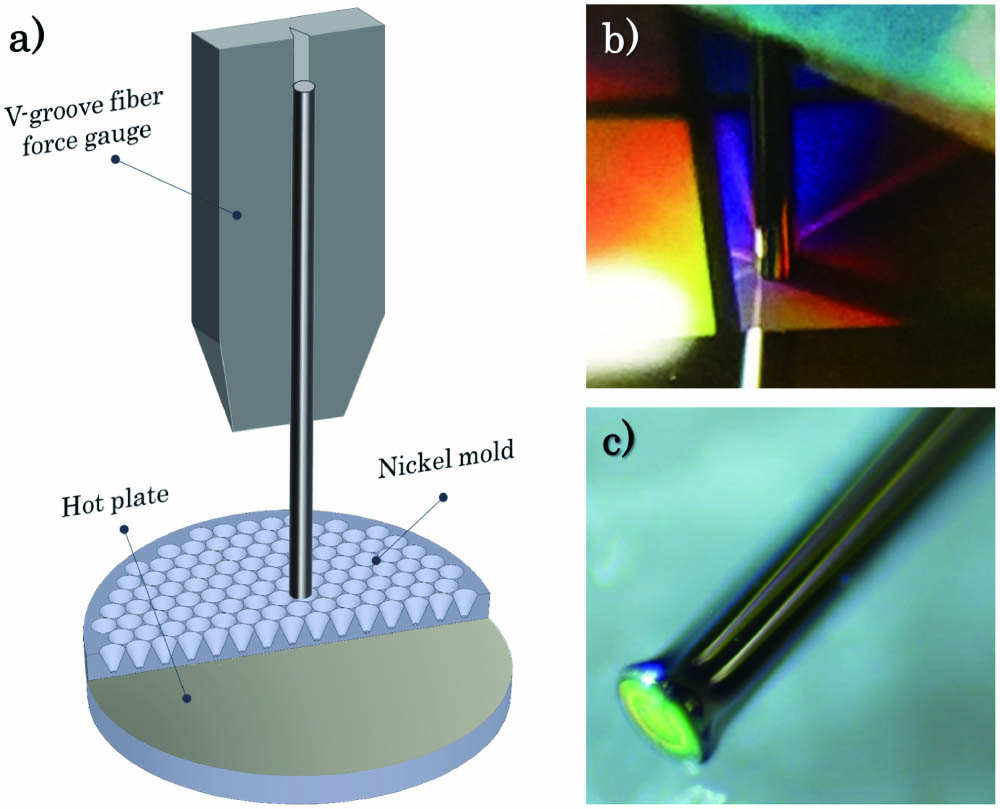
Thermal nanoimprinting was performed by manually pressing fiber end faces down onto a heated nickel (Ni) mold (), as schematically shown in Fig. 1(a).

Figure 1.(a) Illustration of the thermal nanoimprinting principle. (b), (c) Photograph of the fiber (b) during and (c) after imprinting. The different colors are due to the angle and wavelength dependent reflection of the nanostructures.
The fibers were mounted on a V-grooved fiber force gauge (FSC102, Thorlabs) to monitor the imprinting force, and the amount of applied force was controlled manually by a linear translation stage. The temperature of the Ni mold was controlled by fixing it to a hot plate using spring-loaded clamps. The AR pattern of the mold was based on an inverted cone structure with a pitch and height of around 1050 nm and 1000 nm, respectively, modeled to exhibit less than 4% reflection from 2.6 to 6.2 µm. For more details about the fabrication and specifications of the AR structured Ni mold see Lotz et al.[20,27].
The fibers used for testing are listed in Table 1. These include a range of As-Se and Ge-As-Se glasses, large-core and small-core fibers, as well as a PCF and a polymer-chalcogenide MMF. The fibers were imprinted above the transition temperature () of the host glass at a hotplate temperature of for 3–5 s and a force of around 1 N was applied. A longer imprint duration at reduced force was found to cause a larger degree of fiber deformation, simply due to allowing a larger section of the glass to be heated above through thermal radiation and conductivity.
| ID | Core/clad mat. | Core/clad Tg (°C) | Core/clad diam. (µm) | Source |
|---|
| IRF-Se-100 | As39.4Se60.6/As38.6Se61.4 | ≳185/≲185 | 100/170 | IRflex |
| IRF-Se-12 | As39.4Se60.6/As38.6Se61.4 | ≳185/≲185 | 12/170 | IRflex |
| IRF-SeG-12 | As40Se60/Ge12.5As25.0Se62.5 | 185/245a | 12/170 | IRflex |
| PCF | Ge10As22Se68 | 180 | 15/125 | SelenOptics |
| NOTT-11 | As40Se60/Ge10As23.4Se66.6 | 185/185 | 11/220 | Nottingham Univ. (UK) |
| DTU-MMF | As40Se60/PES | 185/224b | 25/650 | DTU Fotonik |
Table 1. Specifications for the Tested Chalcogenide Fibers
3. Results and Discussion
As a first test, the different SIFs were imprinted and subsequently inspected using scanning electron microscopy (SEM) to assess the structural integrity. As seen in Fig. 2, the different SIFs exhibited significantly different behavior when imprinted. In the large-core IRFlex (IRF)-Se-100 fiber [Figs. 2(b) and 2(d)], the cone structure of the Ni mold was fully transferred to both the core and cladding, while, for the corresponding small-core IRF-Se-12 version, the core was observed to be only partially imprinted compared to the surrounding cladding [Figs. 2(a) and 2(c)]. This was the case despite significant deformation of the fiber tip, resulting in an incomplete transfer of the AR structure to the core. In contrast, the imprinted core of the Nottingham (NOTT)-11 SIF was found to protrude from the surrounding cladding, resulting in a very good core imprint even for very limited deformation of the fiber tip [Figs. 2(e) and 2(g)]. It was initially suspected that this phenomenon was related to the fabrication of the fibers and the increased thermo-mechanical disparity between the core and cladding stemming from the addition of germanium (Ge) to the cladding, thereby lowering its thermal expansion coefficient (TEC)[30].
Figure 2.SEM images of imprinted (a), (c), (h) IRF-Se-12, (b), (d) IRF-Se-100, (e), (g) NOTT-11, and (f) IRF-SeG-12 optical fibers.
The NOTT-11 fiber was fabricated by the rod-in-tube technique. The rod was prepared by co-extrusion of the core and cladding glasses into a preform of 10 mm diameter, which was subsequently pulled into a 1 mm diameter cane. A cladding tube of 10 mm outer diameter was similarly produced by extrusion and combined with the core rod for the final preform[31]. Despite Ge lowering the TEC of the cladding glass, the of the core and cladding glasses were carefully matched to avoid built-in thermal stress during cooling. On reheating the NOTT-11 fiber during imprinting, the core glass expanded more than the cladding glass due to TEC mismatch, so it protruded to relieve the thermal expansion mismatch strain.
The fibers from IRF were fabricated using the double-crucible method, where the fibers are directly drawn from the melted core/cladding glasses using a set of inner and outer crucibles[32]. For the IRF-SeG-12 fiber [Fig. 2(f)], core retraction, rather than expansion, was observed upon reheating. This is seen even more clearly in Fig. 2(h), which shows a failed imprint where the fiber was only imprinted on one side of the cladding. In this case, the of the core glass was lower than that of the cladding glass, so after fiber drawing the fiber would have had a fictive temperature profile across it. A permanent, locked-in tensile stress in the core glass would have resulted, because the core was still contracting as a viscous/visco-elastic fluid, but was prevented from doing so when the cladding glass solidified during cooling. Upon reheating this fiber, the core glass, being under tension, was able to recoup the contraction, resulting in the observed partial imprinting.
For the IRF-Se-12 fiber there is no Ge in the cladding to explain this behavior. Instead, the As content is higher, which results in a higher and lower TEC[33]. Again, since the TEC is lowered, the cladding expanded more than the core during imprinting, thus achieving the same effect.
The consequence of partial imprinting is a reduced AR efficiency, which can shift the transmission peak wavelength and reduce the overall transmission by several percent. This is illustrated in Fig. 3(a), which shows a simulation of the maximum transmission of a single imprinted interface for varying degrees of imprint completeness based on rigorous coupled-wave analysis[20].
Figure 3.(a) Calculated single-interface transmission for varying degrees of imprint completeness. (b) Zoom-in on the core/clad interface of the imprinted IRF-Se-12 fiber used to estimate the imprint height (<75%).
From Fig. 3(b), it is estimated that the imprint in the core of the IRF-Se-12 fiber was less than 75% of the height of the ideal structure, which is expected to cause 1%–6% increased reflection depending on the wavelength and a shift in peak transmission from to 3.8 µm. One important observation is that a diameter region in the center of the core in Fig. 2(c) was fully imprinted, which indicates that the outer rim of the core was flow-restricted due to the surrounding material. Therefore, in order to improve the imprint quality of the entire core area, the fiber was fitted into a ceramic ferrule, as shown in Figs. 4(a) and 4(b), to apply a compressive stress to the fiber during imprinting. In this configuration, fiber tip deformation was significantly reduced while also vastly improving the handling and overall rigidity of the fiber. The results are shown in Figs. 4(b)–4(e) for the IRF-Se-12 fiber, in which the core is now barely distinguishable from the cladding.
Figure 4.(a) Optical microscope image of the imprinted fiber end face, reflecting red light at this particular angle. (b) SEM image of the imprinted end face protruding slightly from the ferrule. (c), (d) Close up of the imprinted core area at different angles. The dashed white line indicates the core area. (e) The white arrows show the region where a slight difference in the gray level indicates the interface between core and cladding.
Having obtained a full imprint on all test fibers, the transmission was then tested, and the results are summarized in Table 2. The length of the test fibers was around 15–25 cm, and the imprints were tested using a broadband mid-IR SC laser covering from 2 to 4.3 µm, as illustrated in Figs. 5(a) and 5(b). A long-pass filter with 2 µm cut-on wavelength was used to filter out the near-IR part of the laser where the fibers have higher losses, and the periodic structure acts as a diffraction grating[19]. Light was coupled to the fibers using aspheric chalcogenide lenses with a focal length of 12 mm for the large-core fibers and 6 mm for the small-core fibers. The lenses had a measured total loss of around 7% over the SC laser bandwidth. The fiber output power was measured directly out of the fiber using a thermal power meter, with the absorbing element placed in close proximity to the fiber end face. The output spectrum was measured using a grating-based scanning spectrometer via butt-coupling of the fiber output to a 150 µm core diameter indium fluoride patch cable. The best result was obtained using the large-core IRF-Se-100 fiber, which saw a 32.4% increase in transmission, compared to a 29.4% increase in the corresponding small-core fiber. Figure 5(c) shows the gradual improvement in transmission from the bare fiber (55.9%), after imprinting the input face (70.7%), and after imprinting both faces (88.3%). The figure also shows the calculated residual loss due to reflections, which amounts to 3.2% and 4.5% for the input and output faces, respectively.
Figure 5.(a) Test setup for measuring fiber transmission (M1/M2, silver mirror; LPF, long-pass filter; AL, aspheric lens; TPM, thermal power meter). (b) Pump and transmission spectra of the IRF-Se-100 fiber before and after imprinting the input face. (c) Bar plot illustrating the increasing transmission due to imprinting IRF-Se-100.
| ID | T0 (%) | T1 (%) | T2 (%) | ΔT (%) |
|---|
| IRF-Se-100 | 55.9 | 70.74 | 88.3 | 32.4 |
| IRF-Se-12 | 58.7 | 71.9 | 88.1 | 29.4 |
| PCFa | 53.3 | – | 73.8 | 20.6 |
| NOTT-11 | 50.7 | – | 71.2 | 20.5 |
| DTU-MMF | – | – | 20.8 | – |
Table 2. Best AR results
The remaining 4% loss is attributed to intrinsic fiber losses. To avoid oxidation, it is generally recommended to perform imprinting in an inert gas environment. However, in this work, imprinting was performed under ambient laboratory conditions, and the fibers were tested shortly after imprinting. This could potentially have contributed to reducing the maximum achievable transmission.
The lowest transmission increase of 20.5% was found in the 17.5 cm long NOTT-11 fiber, similar to what was achieved with PCFs in another recent study[19]. The lower transmission improvement could be due to the core protrusion, causing reduced imprinting of the cladding and, thus, potentially increased reflection or scattering at the core/clad interfaces. This effect could possibly have been handled in the same way that core contraction was prevented in the commercial fibers, but because of the custom outer diameter of the fiber such a solution would require custom ferrules, and so this solution was not pursued. The NOTT-11 fiber also had not undergone any special purification processing, and so the higher loss may have affected the ability to increase the transmission by nanoimprinting. Lastly, since the core and cladding glasses of this fiber have undergone several heating stages during fabrication, there is also a chance that imprinting could have initiated crystallization of the glass[34].
As a final demonstration, the MMF with glass core and polymer cladding was imprinted. The fiber was fabricated at DTU Fotonik using the rod-in-tube technique with an core rod and polyethersulfone (PES) thermoplastic cladding tube. The final drawn fiber had a core diameter of 25 µm and cladding diameter of around 650 µm. Due to the very thick polymer cladding, the fiber was very rigid and robust, but also very difficult to cleave. Consequently, the fiber could not be cleaved using conventional tension cleavers, and even a custom-heated blade cleaver made specifically for cleaving polymer fibers could not produce smooth cleaves. The best cleaves were obtained by cutting through part of the cladding around the circumference of the fiber with a scalpel and then applying force to chip off the fiber tip. Such a cleave is shown in Fig. 6(a). It is clear from the microscope image in Fig. 6(b), that due to the large difference in mechanical properties, the PES detached from the core near the end face. However, this is merely a superficial effect, which was confirmed by polishing the fiber, as seen in Fig. 6(c). Unfortunately, polishing polymers is not easy, and, as a result, a lot of debris settled on the core of the fiber, leading to damage when tested. In this case, imprinting was used as a way of not only consolidating the core and cladding, but also as a means of providing a good optical surface for coupling in light. For this reason, the transmission improvement of the imprinted structure was not tested in this fiber, but core transmission was confirmed, and the imprint quality and structural integrity were confirmed by SEM image, as shown in Fig. 6(d). After imprinting both the input and output faces, a total transmitted power of 2.7 mW out of 13 mW pump power (20.8%) was obtained in a length of fiber. The significantly lower transmission of this fiber was primarily due to the evanescent-field absorption of the polymer cladding.
Figure 6.(a) Typical MMF end face after cleaving. (b) Close up on the core area showing core delamination near the face. (c) Polished end face showing consolidation between core and clad, as well as the presence of PES debris. (d) Imprinted end face.
4. Conclusion
In conclusion, thermal nanoimprinting of chalcogenide glass fibers is a simple, fast, and versatile method for reducing Fresnel reflections over a broad bandwidth. The process does not necessarily require clean room conditions nor specialized deposition equipment and can be easily implemented in a typical laboratory environment. In this work, the mismatch in thermo-mechanical properties between core and cladding glasses was for the first time, to the best of our knowledge, shown to have significant implications for nanoimprinting on small-core fibers. Complete transfer of the AR structure to the small-core fibers was achieved by fitting the fibers into ferrules to restrict the thermal expansion. As a result, the around 40% total reflection from commercial 100 µm and 12 µm core chalcogenide fibers was on average reduced over a bandwidth covering from 2 to 4.3 µm by 32.4% and 29.4%, respectively. Lastly, nanoimprinting on a polymer-chalcogenide MMF was demonstrated for the first time, to the best of our knowledge, not only to achieve AR properties, but also as a viable alternative to polishing. Nanoimprinting thus offers a convenient path towards more efficient mid-IR fiber-based systems, including SC lasers, which has found applications within spectroscopic microscopy[35,36], optical coherence tomography[37,38], and spectroscopy[39,40].
References
[1] N. S. Kapany, R. J. Simms. Recent developments in infrared fiber optics. Infrared Phys., 5, 69(1965).
[2] J. Heo, M. Rodrigues, S. J. Saggese, G. H. Sigel. Remote fiber-optic chemical sensing using evanescent-wave interactions in chalcogenide glass fibers. Appl. Opt., 30, 3944(1991).
[3] C. Markos, O. Bang. Nonlinear label-free biosensing with high sensitivity using As2S3 chalcogenide tapered fiber. J. Lightwave Technol., 33, 2892(2015).
[4] L. Sojka, Z. Tang, D. Jayasuriya, M. Shen, J. Nunes, D. Furniss, M. Farries, T. M. Benson, A. B. Seddon, S. Sujecki. Milliwatt-level spontaneous emission across the 3.5–8 µm spectral region from Pr3+ doped selenide chalcogenide fiber pumped with a laser diode. Appl. Sci., 10, 539(2020).
[5] B. Bureau, C. Boussard, S. Cui, R. Chahal, M. L. Anne, V. Nazabal, O. Sire, O. Loréal, P. Lucas, V. Monbet, J.-L. Doualan, P. Camy, H. Tariel, F. Charpentier, L. Quetel, J.-L. Adam, J. Lucas. Chalcogenide optical fibers for mid-infrared sensing. Opt. Eng., 53, 027101(2014).
[6] C. R. Petersen, U. Møller, I. Kubat, B. Zhou, S. Dupont, J. Ramsay, T. Benson, S. Sujecki, N. Abdel-Moneim, Z. Tang, D. Furniss, A. Seddon, O. Bang. Mid-infrared supercontinuum covering the 1.4–13.3 µm molecular fingerprint region using ultra-high NA chalcogenide step-index fibre. Nat. Photon., 8, 830(2014).
[7] R. A. Martinez, G. Plant, K. Guo, B. Janiszewski, M. J. Freeman, R. L. Maynard, M. N. Islam, F. L. Terry, O. Alvarez, F. Chenard, R. Bedford, R. Gibson, A. I. Ifarraguerri. Mid-infrared supercontinuum generation from 1.6 to >11 µm using concatenated step-index fluoride and chalcogenide fibers. Opt. Lett., 43, 296(2018).
[8] S. Venck, F. St-Hilaire, L. Brilland, A. N. Ghosh, R. Chahal, C. Caillaud, M. Meneghetti, J. Troles, F. Joulain, S. Cozic, S. Poulain, G. Huss, M. Rochette, J. M. Dudley, T. Sylvestre. 2–10 µm mid-infrared fiber-based supercontinuum laser source: experiment and simulation. Laser Photon. Rev., 14, 2000011(2020).
[9] B. Zhang, Y. Yu, C. Zhai, S. Qi, Y. Wang, A. Yang, X. Gai, R. Wang, Z. Yang, B. Luther-Davies. High brightness 2.2–12 µm mid-infrared supercontinuum generation in a nontoxic chalcogenide step-index fiber. J. Am. Ceram. Soc., 99, 2565(2016).
[10] T. Cheng, K. Nagasaka, T. H. Tuan, X. Xue, M. Matsumoto, H. Tezuka, T. Suzuki, Y. Ohishi. Mid-infrared supercontinuum generation spanning 2.0 to 15.1 µm in a chalcogenide step-index fiber. Opt. Lett., 41, 2117(2016).
[11] Z. Zhao, B. Wu, X. Wang, Z. Pan, Z. Liu, P. Zhang, X. Shen, Q. Nie, S. Dai, R. Wang. Mid-infrared supercontinuum covering 2.0–16 µm in a low-loss telluride single-mode fiber. Laser Photon. Rev., 11, 1700005(2017).
[12] Z. Tang, V. S. Shiryaev, D. Furniss, L. Sojka, S. Sujecki, T. M. Benson, A. B. Seddon, M. F. Churbanov. Low loss Ge-As-Se chalcogenide glass fiber, fabricated using extruded preform, for mid-infrared photonics. Opt. Mater. Express, 5, 1722(2015).
[13]
[14] A. Sincore, J. Cook, F. Tan, A. El Halawany, A. Riggins, S. McDaniel, G. Cook, D. V. Martyshkin, V. V. Fedorov, S. B. Mirov, L. Shah, A. F. Abouraddy, M. C. Richardson, K. L. Schepler. High power single-mode delivery of mid-infrared sources through chalcogenide fiber. Opt. Express, 26, 7313(2018).
[15] L. E. Busse, C. Florea, B. Shaw, V. Nguyen, J. S. Sanghera, I. Aggarwal, F. Kung. Antireflective surface structures on IR fibers for high power transmission. Advanced Solid State Lasers, AM2A-5(2013).
[16] M.-H. Lee, D.-Y. Khang. Facile generation of surface structures having opposite tone in metal-assisted chemical etching of Si: pillars vs. holes. RSC Adv., 3, 26313(2013).
[17] Y. Kanamori, M. Okochi, K. Hane. Fabrication of antireflection subwavelength gratings at the tips of optical fibers using UV nanoimprint lithography. Opt. Express, 21, 322(2013).
[18] C. Florea, J. Sanghera, L. Busse, B. Shaw, F. Miklos, I. Aggarwal. Reduced Fresnel losses in chalcogenide fibers obtained through fiber-end microstructuring. Appl. Opt., 50, 17(2011).
[19] C. R. Petersen, M. B. Lotz, G. Woyessa, A. N. Ghosh, T. Sylvestre, L. Brilland, J. Troles, M. H. Jakobsen, R. Taboryski, O. Bang. Nanoimprinting and tapering of chalcogenide photonic crystal fibers for cascaded supercontinuum generation. Opt. Lett., 44, 5505(2019).
[20] M. R. Lotz, C. R. Petersen, C. Markos, O. Bang, M. H. Jakobsen, R. Taboryski. Direct nanoimprinting of moth-eye structures in chalcogenide glass for broadband antireflection in the mid-infrared. Optica, 5, 557(2018).
[21] R. J. Weiblen, C. R. Menyuk, L. E. Busse, L. B. Shaw, J. S. Sanghera, I. D. Aggarwal. Optimized moth-eye anti-reflective structures for As2S3 chalcogenide optical fibers. Opt. Express, 24, 10172(2016).
[22] Z. Zmrhalová, P. Pilný, R. Svoboda, J. Shánělová, J. Málek. Thermal properties and viscous flow behavior of As2Se3 glass. J. Alloys Compd., 655, 220(2016).
[23] Z. G. Lian, W. Pan, D. Furniss, T. M. Benson, A. B. Seddon, T. Kohoutek, J. Orava, T. Wagner. Embossing of chalcogenide glasses: monomode rib optical waveguides in evaporated thin films. Opt. Lett., 34, 1234(2009).
[24] N. Ostrovsky, D. Yehuda, S. Tzadka, E. Kassis, S. Joseph, M. Schvartzman. Direct imprint of optical functionalities on free-form chalcogenide glasses. Adv. Opt. Mater., 7, 1900652(2019).
[25] Y. Zou, L. Moreel, H. Lin, J. Zhou, L. Li, S. Danto, J. D. Musgraves, E. Koontz, K. Richardson, K. D. Dobson, R. Birkmire, J. Hu. Solution processing and resist-free nanoimprint fabrication of thin film chalcogenide glass devices: inorganic-organic hybrid photonic integration. Adv. Opt. Mater., 2, 759(2014).
[26] B. D. MacLeod, D. S. Hobbs, E. Sabatino. Moldable AR microstructures for improved laser transmission and damage resistance in CIRCM fiber optic beam delivery systems. Proc. SPIE, 8016, 80160Q(2011).
[27] M. Lotz, J. Needham, M. H. Jakobsen, R. Taboryski. Nanoimprinting reflow modified moth-eye structures in chalcogenide glass for enhanced broadband antireflection in the mid-infrared. Opt. Lett., 44, 4383(2019).
[28] A. Prasad, C.-J. Zho, R.-P. Wang, A. Smith, S. Madden, B. Luther-Davies. Properties of GexAsySe1-x-y glasses for all-optical signal processing. Opt. Express, 16, 2804(2008).
[29] A. Linares, R. Benavente. Effect of sulfonation on thermal, mechanical, and electrical properties of blends based on polysulfones. Polym. J., 41, 407(2009).
[30] J. H. Savage. Infrared Optical Materials and Their Antireflection Coatings(1985).
[31] S. D. Savage, C. A. Miller, D. Furniss, A. B. Seddon. Extrusion of chalcogenide glass preforms and drawing to multimode optical fibers. J. Non-Cryst. Solids, 354, 3418(2008).
[32] G. Tao, H. Ebendorff-Heidepriem, A. M. Stolyarov, S. Danto, J. V. Badding, Y. Fink, J. Ballato, A. F. Abouraddy. Infrared fibers. Adv. Opt. Photon., 7, 379(2015).
[33] J. D. Musgraves, P. Wachtel, S. Novak, J. Wilkinson, K. Richardson. Composition dependence of the viscosity and other physical properties in the arsenic selenide glass system. J. Appl. Phys., 110, 063503(2011).
[34] P. Toupin, L. Brilland, J. Troles, J.-L. Adam. Small core Ge-As-Se microstructured optical fiber with single-mode propagation and low optical losses. Opt. Mater. Express, 2, 1359(2012).
[35] C. R. Petersen, N. Prtljaga, M. Farries, J. Ward, B. Napier, G. R. Lloyd, J. Nallala, N. Stone, O. Bang. Mid-infrared multispectral tissue imaging using a chalcogenide fiber supercontinuum source. Opt. Lett., 43, 999(2018).
[36] F. Borondics, M. Jossent, C. Sandt, L. Lavoute, D. Gaponov, A. Hideur, P. Dumas, S. Février. Supercontinuum-based Fourier transform infrared spectromicroscopy. Optica, 5, 378(2018).
[37] N. M. Israelsen, C. R. Petersen, A. Barh, D. Jain, M. Jensen, G. Hannesschläger, P. Tidemand-Lichtenberg, C. Pedersen, A. Podoleanu, O. Bang. Real-time high-resolution mid-infrared optical coherence tomography. Light Sci. Appl., 8, 11(2019).
[38] I. Zorin, P. Gattinger, M. Brandstetter, B. Heise. Dual-band infrared optical coherence tomography using a single supercontinuum source. Opt. Express, 28, 7858(2020).
[39] C. R. Petersen, P. M. Moselund, L. Huot, L. Hooper, O. Bang. Towards a table-top synchrotron based on supercontinuum generation. Infrared Phys. Technol., 91, 182(2018).
[40] K. Eslami Jahromi, M. Nematollahi, Q. Pan, M. A. Abbas, S. M. Cristescu, F. J. M. Harren, A. Khodabakhsh. Sensitive multi-species trace gas sensor based on a high repetition rate mid-infrared supercontinuum source. Opt. Express, 28, 26091(2020).