The current study is directed to the rapidly developing field of inorganic material 3D object production at nano-/micro scale. The fabrication method includes laser lithography of hybrid organic-inorganic materials with subsequent heat treatment leading to a variety of crystalline phases in 3D structures. In this work, it was examined a series of organometallic polymer precursors with different silicon (Si) and zirconium (Zr) molar ratios, ranging from 9:1 to 5:5, prepared via sol-gel method. All mixtures were examined for perspective to be used in 3D laser manufacturing by fabricating nano- and micro-feature sized structures. Their spatial downscaling and surface morphology were evaluated depending on chemical composition and crystallographic phase. The appearance of a crystalline phase was proven using single-crystal X-ray diffraction analysis, which revealed a lower crystallization temperature for microstructures compared to bulk materials. Fabricated 3D objects retained a complex geometry without any distortion after heat treatment up to 1400 °C. Under the proper conditions, a wide variety of crystalline phases as well as zircon (ZrSiO4 - a highly stable material) can be observed. In addition, the highest new record of achieved resolution below 60 nm has been reached. The proposed preparation protocol can be used to manufacture micro/nano-devices with high precision and resistance to high temperature and aggressive environment.
Introduction
There is no doubt that ceramics and ceramic-like materials cover an important part of science and industry, due to outstanding thermal, mechanical, chemical properties1. The ability to produce micro- or even nano-scale objects possessing such properties is a topic continuously of growing attention. 3D ceramic objects can be produced using a multitude of 3D printing techniques, such as slurry-based (stereolithography, digital light processing, two-photon polymerization, injection printing, direct ink writing), powder-based (three-dimensional printing, selective laser sintering or melting), and bulk-solid based (laminated object manufacturing and fused deposition modeling)2. Common procedures in all those listed methods are the application of ceramic particles suspension3, 4 or metals salts5-7 in an organic medium, which is necessary for chemical network formation. Such an approach is suitable for relatively large-scale 3D ceramic object formation, however, the main drawback of such method is relatively low achievable resolution - readily not suitable for optical/photonic applications. One of the viable approaches to overcome this limitation is the usage of homogeneous hybrid organic-inorganic compounds for laser lithography with an additional calcination step8-10 . The benefit of this method is the initiation of photochemical reactions with a tightly focused ultrashort pulsed light beam for 3D structuring. The homogenous organic-inorganic hybrid compound consists of two major parts: organic functional residue taking part in photopolymerization and inorganic residue leading to ceramic material after post-processing. Combining such methodology results in a well defined as high resolution micro-and nanoscale 3D glass-ceramic crystalline objects. Up to now, a wide variety of materials such as acrylates, epoxies, hydrogels, hybrids, or biopolymers were used in a 3D laser printing11. It can be expected that such an abundance of tested materials will lead to nanoscale resolution of printed structures. Nanoscale features (65 ± 5 nm) have been achieved a while ago using the organic DABP-triacrylate resin12. However, organic materials have serious limitations regarding stability against the harsh environments. The highest reported resolved features for Zr-organic hybrid material is 45 nm achieved with sub-10 fs laser pulses13. It is worth to mention that the fabricated structures are delicate in nature because even an electron microscope beam induces a serious irreversible deformation. Such mild mechanical properties can be attributed to the high content of remaining organic material13. Thus it brings challenges in handling and manipulating such tiny structures. Recently, fabrication of a true-3D inorganic ceramics with an average 85 ± 10 nm line cross-section was demonstrated using a sol-gel resist precursor, yet still restricted to a single outcoming substance8.
Pure inorganic structures are obtained after high temperature treatment of inorganic-organic hybrid materials. After heat treatment, the derivatives shrink in size, increase in density and hardness, following with improved mechanical and chemical stability14, 15. In 2018 Seniutinas et al. obtained ≈25 nm line width of buckyball by combining pyrolysis and oxygen plasma etching as post-processing steps16. Nevertheless, the demonstrated method was appropriate for obtaining simple thin structures, being based on the etching of the top layer of building material. This approach would be cumbersome for the production of more complex 3D or periodic bulk architectures. Sintering of hybrid materials is attractive not only because of the shrinkage in dimensions but also due to the formation of new crystalline phases expanding the application possibilities. With this in mind, the application of combined Si and Zr precursors following the thermal treatment under oxidative atmosphere open the possibility for the formation of various crystalline phases with distinctive chemical and physical properties17-19.
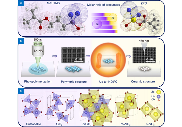
To sum up, precursors with properties required for fabrication are an essential prerequisite for micro- and nano-dimension ceramic frameworks made by laser 3D lithography (Fig. 1(a)). Thus, the search of new precursors suitable for laser 3D polymerization remains an urgent and timely task (Fig. 1(b)).
Figure 1.Graphical abstract showing precursors, their molar ratios in (a) syntheses, (b) photopolymerization and calcination technology and (c) formed crystalline phase lattices after calcination (Cristobalite, SiO2, ZrSiO4, monoclinic ZrO2 and tetragonal ZrO2). These phases can be observed depending on the treatment temperature and initial hybrid materials compositions.
Here we take over the state-of-the art to a new level in the sense of fabrication resolution, reproducibility and control of 3D structurable materials (Fig. 1(c)). Furthermore, the proposed approach is not limited to a specific LDW setup or hybrid material class - on the contrary becoming a new paradigm for the nano-structuring of inorganics in arbitrary 3D geometries. This has immediate applications for miniature and integrated, highly resilient and heavy duty opto-electronic devices.
Results and discussion
For inorganic material printing with predictable phase composition the metalorganic silicon and zirconium mixtures with variable composition was selected. In order to find out the suitability of such precursors for 3D micro/nano scale printing the different variations of the precursor SiX:ZrY were synthesized, characterized and 3D laser exposure and heat treatment experiments were performed. The material in focus is a modified silicate (ORMOSIL®) class sol-gel resist originating from SZ2080TM20.
Initial characterization of selected mixtures include evaluation of refractive index for selected mixtures. The index data is provided in Supplementary information
Fig. S2, indicating that for gel mixtures values are greater than 1.50 (except Si9:Zr1) and can be attributed to high-refractive-index polymers (HRIP). High refractive-index value is convenient for spherical aberration-free laser fabrication procedures, more specific information is given in 2008 Ovsianikov et al. publication20. The Fourier transform infrared spectroscopy (FTIR) measurements of post synthesis liquid and gel precursors were done. Peak intensities in FTIR spectra, attributed to Si-O-Si (1130–1000 cm–1), Zr-O-Zr (500–400 cm–1) and Si-O-Zr (1000–900 cm–1) correlate with initial precursor concentration. Increasing Si precursor concentration results in more intense Si-O-Si bond absorption peaks in polymerized mixtures. The analogous trend is visible for Zr precursor concentration increase. However, absorption peaks of Si-O-Zr overlap and derive clear bond concentration trends for different mixture variations is cumbersome. Detailed description of experimental data is in Supplementary information
Fig. S1. Based on FTIR and refractive-index data the selected synthesis procedure is considered valid for further examination.
Figure 2.(a) TGA data of SiX:ZrY showing weight loss vs. temperature (red line). (b) Theoretical (square symbols) and practical (circle symbols) weight loss for the phase transition from the polymeric to the glass/ceramic phase (black) and volumetric shrinkage (red) (theoretical- square symbols, practical- circle symbols) of cubes at the same phase transition (error bars of volumetric shrinkage represent Std. dev., n = 3, TGA measurements were performed once for each material, so it is not possible to include error bars for the weight loss). SEM images of the Si7:Zr3 cube before (c) and after (d) heat treatment at 1000 °C.
Thermogravimetric analysis data for different ratio SiX:ZrY materials are depicted in (Fig. 2). In Fig. 2(a) red lines show weight loss dependence on temperature. The initial sharp weight loss (up to ≈140 °C) is attributed to evaporation of solvents, such as methanol and isopropyl alcohol. Based on FTIR data it can be concluded that materials reach almost complete thermall polymerization at 140°C temperature (double C = C bond (1650 cm–1) signal intensity, while for polymers this signal almost disappear21 (see Supplementary information
Fig. S1(c)). Thermal polymerization temperature determination for prepared mixtures was necessary in order to properly compare weight loss for laser printed structures during annealing. Initial weight is set to 100% at 150 °C, based on assumption that polymerization is complete and bulk polymerized mixtures are similar to laser printed material. The weight loss patterns indicate that decomposition of organic moiety is finished at 600–700 °C temperature range. The weight stabilization at higher temperature points out the inorganic material formation. TGA data reveals that with increasing silicon content, weight loss increases and it ranges from 51% to 62% (Fig. 2(b)). It is necessary to mention that with a higher amount of zirconium, the inorganic material is achieved at lower temperature. The weight loss and volume shrinkage comparison is depicted in Fig. 2(b). The volume change after heating was estimated by measuring volume of fabricated cubes. The volumetric shrinkage was calculated employing the equation:
where V(initial) is a volume of cube before heat treatment, V(final) - after heat treatment. cubes outcontained set of three cubes out of which standard deviation (%) was calculated. The error ranges from 0.56 to 3.70 percent, with lowest values for Si:Zr 8:2 composition and highest for Si:Zr 5:5 composition. The low deviation from mean value brings to conclusion that 3D structure fabrication and post heat treatment are repeatable and reliable. All experimental data are provided in Supplementary information
Table S1. Data in Fig. 2(b) bring to conclusion, that denser ceramic structures are obtained by increasing the silicon content, while theoretical prognosis is opposite. The calculated volume shrinkage should increase with higher zirconium content, because crystalline zirconia is much denser than silica. The assumptions made for calculations are provided in Supplementary information. The fabricated cubes contained an unknown amount of amorphous phase after annealing at 1000 °C. It can be assumed that a higher amount of amorphous zirconia should be present compared to silica which crystallizes at lower temperature22, 23. Therefore, the trend in experimental data is opposite to the predicted (Fig. 2(b)).
To clarify the fabrication prospects of proposed mixtures, woodpiles were fabricated (Fig. 3). It was found that the highest resolution of the inorganic structure (58.7 ± 1.5 nm) is achieved for Si9:Zr1 material using 64 µW power and 200 µm/s velocity followed by annealing at 1000 °C (Fig. 3(f)). The higher power was not used due to uncontrolled burning of Si9:Zr1 material at 300 fs pulses, 515 nm central wavelength and 1.4 NA objective focusing conditions. To the best of our knowledge this is the highest resolution for inorganic 3D ceramic derivative achieved by printing up to this day. The same woodpiles were fabricated with all hybrids for resolution comparison of all materials. The dependence of woodpile lines width on the laser energy density is shown in Fig. 3(g, f) and the numerical values are listed in Supplementary information
Tables S2,
S3,
S4, and
S5. At lower energy densities it is difficult to get a clear relationship between resolution and material composition, nevertheless, at higher laser energy densities (from 24 μJ/μm3 to 32 μJ/μm3) it is evident that the resolution is higher where the zirconium content is lower. In prepared mixtures, the zirconium amount is linked to the methacrylic acid, while the silicon amount corresponds to the methyl methacrylate functional group. The resolution dependence of 3D derivatives changing composition can be explained by the fact that the photopolymerization activation energy of methacrylic acid is several times lower than the activation energy of the methyl methacrylate under the same conditions (Ea(methacrylic acid) = 1.79 kCal/mol, Ea(methyl methacrylate) = 4.48 kCal/mol)24. The same laser energy density tends to polymerize a larger volume of material with a lower photopolymerization activation energy during the unit pulse. However, photopolymerization activation energy may also depend on the influence of adjacent functional groups, photoinitiators, quenchers, and/or ambient conditions25. The printed structure treatment in a developing solvent after photopolymerization can also affect the resolution due to the solvent ability to dissolve the unpolymerized monomer molecules at the phase junction between polymer and gel. The higher solvent affinity to substance and the lower molecular weight or less branched structure of the molecule (steric effect), the better solubility is achieved26. Also, the increase in molecular weight in most cases leads to a decrease in solubility because the increase in molecular weight increases the cohesive energy density (CED), where, according to J. Hildebrand, the solubility parameter is the square root of the CED27. The molecular weight and branching are smaller for zirconium and methacrylic acid monomer compared to silicon monomer. Accordingly, as the zirconium content increases, the resolution of the 3D structure should increase too, different from the reaction activation energy influence. The competition takes place between two opposing processes. This fact explains why it is difficult to see the evident dependence of the resolution on the composition of the material at low laser energy densities. Similarly, the easier penetration of the solvent into the material can affect the swelling of the polymeric structure. It is important to mention that the solubility of materials depends on many factors, thus it is used here only for a comparison.
Figure 3.Si9:Zr1 woodpiles (a–c) before heat treatment and (d–f) after heating at 1000 °C under air atmosphere. (a, d) Woodpiles fabricated at 200 μm/s speed (on the top line) and at 500 μm/s speed (on the bottom line) with 48, 56, 64 μW incident irradiation power. (b, c, e, and f) The highest resolution of woodpiles was obtained by applying 200 μm/s and 64 μW parameters. (g) The dependence of Si9:Zr1, Si7:Zr3, Si5:Zr5 woodpiles lines width on the laser irradiance at 200 μm/s speed. Before heat treatment- solid lines, after- dashed lines. (h) The dependence of Si9:Zr1, Si7:Zr3, Si5:Zr5 woodpiles lines width on the laser irradiance at 500 μm/s speed (error bars represent Std. dev., n = 3).
In Figs. 4, 5, 6 XRD data of scaffolds (a–e) and corresponding powders (g–l) are presented for samples annealed at 1000 °C, 1200 °C and 1400 °C respectively. The color of all structures and powders was white, indicating that no organic contaminants remained after annealing. The quality of the skeleton surface and the absence of porosity are confirmed by SEM images depicted in supplementary information Fig. S3. It is obvious that the porous structure is obtained only by a structure made of Si9:Zr1 material. At the lowest annealing temperature (Fig. 4) in both, scaffolds and powders, the formation of crystalline cristobalite and tetragonal ZrO2 phases are observed. Increasing zirconium amount leads to a more pronounced tetragonal ZrO2 crystalline phase. However, a relatively high background in diffractograms indicates the presence of an amorphous phase. No visible deformations in 3D structures were observed for all series of samples with different compositions after calcination at 1000 °C. With increasing annealing temperature to 1200 °C (Fig. 5) leads to samples, both powder, and structures, with higher crystallinity. However, X-ray diffraction data for all samples still provide evidence of glassy amorphous phase presence. Diffractogram of Si5:Zr5 3D structure shows that the cristobalite phase remains as pronounced as tetragonal ZrO2, while different behavior is observed for powder sample, tetragonal ZrO2 phase is dominating. In order to find out why the XRD spectra of powders and 3D structures look so different, an extensive study should be done. However, we can assume that the difference in the amount of material (in the case of structure is very small) or the presence and absence of polymerization before annealing results in a difference in the XRD spectra due to diffusion or heat distribution discrepancies. Each 3D structure preserves its shape after 1200 °C heat treatment, except Si9:Zr1. The materials with the higher initial amount of silicon, start to melt due to the lower melting temperature of silicon oxide compared to zirconium oxides. The most stable zirconium dioxide phase is monoclinic, while tetragonal and cubic phases tend to form at higher temperatures28. However, in our study, the monoclinic ZrO2 phase formed only at 1400 °C (see Fig. 6(a–g)), while tetragonal dominated at all annealing temperatures and starting compositions (except Fig. 6(g)). Such phenomenon can be explained using Ostwald's Step Rule, stating that phase formation follow a general pattern when phases with the highest energy are formed first following the transition to lower energy phases29, 30. This means that the higher energy metastable tetragonal phase is frozen in prepared samples. Recently, A. Auxéméry et al. demonstrated that it is possible to stabilize metastable tetragonal ZrO2 not only by cationic substitution but it can be achieved by varying the synthesis conditions31. In summary, differences between the amounts of elements, such as Si, Zr, and O, before and after heat treatment, result in distinct ratios of the formed crystalline phases and the creation of further, higher or lower energy phases, although heated at the same temperature.
Figure 4.X-ray diffractograms of structures (SEM images) annealed at 1000 °C (a-Si5:Zr5, b-Si6:Zr4, c-Si7:Zr3, d-Si8:Zr2, e-Si9:Zr1, f-reference data) and X-ray diffractograms of powders annealed at 1000 °C (g-Si5:Zr5, h-Si6:Zr4, i-Si7:Zr3, j-Si8:Zr2, k-Si9:Zr1, l-reference data). SEM images show corresponding 3D scaffolds treated at 1000 °C. SEM images correspond to the same scale bar.
Figure 5.X-ray diffractograms of structures (SEM images) annealed at 1200 °C (a-Si5:Zr5, b-Si6:Zr4, c-Si7:Zr3, d-Si8:Zr2, e-Si9:Zr1, f-reference data) and X-ray diffractograms of powders annealed at 1200 °C (g-Si5:Zr5, h-Si6:Zr4, i-Si7:Zr3, j-Si8:Zr2, k-Si9:Zr1, l-reference data). SEM images show corresponding 3D scaffolds treated at 1200 °C temperature. SEM images correspond to the same scale bar.
Figure 6.X-ray diffractograms of structures (SEM images) annealed at 1400 °C (a-Si5:Zr5, b-Si6:Zr4, c-Si7:Zr3, d-Si8:Zr2, e-Si9:Zr1, f-reference data) and X-ray diffractograms of powders annealed at 1400 °C (g-Si5:Zr5, h-Si6:Zr4, i-Si7:Zr3, j-Si8:Zr2, k-Si9:Zr2, l-reference data). SEM images show corresponding 3D scaffolds treated at 1400 °C temperature. SEM images correspond to the same scale bar.
Moreover, the resistance of ceramic structures to aggressive chemicals has also been investigated and the results are depicted in the Supplementary Information
Fig. S5. This study confirmed that ceramic structures have a higher resistance to chemicals compared to the corresponding polymeric.
The strong adhesion to the substrate and high robustness in negative temperatures was validated by flushing the 3D nanostructures directly with liquid nitrogen down to −196 °C (≈77 K) for 10 min and letting it evaporate freely. No detachment, delamination, or fracture of the structures was observed due to rapid cooling / heating impact at low temperatures, shown in Fig. S4 of the Supplementary.
Currently, thermal post-treatment is being established as a technique for downscaling or improving the properties of the laser additively manufactured 3D nanostructures. For instance, it was reported to apply pyrolysis at 900 °C for production of carbon nanowires, which was successful for both downscaling the features and converting the compound into a new substance32.
However, the resulting material made of purely organic resin was still an organic one, though with significantly improved properties such as high isotropy, electrochemical stability, biocompatibility, chemical resistance, and semiconductor-like electrical parameters, making it attractive for manufacturing Carbon-MEMS.
In parallel, a single crack-free pre-ceramic resin for two-photon lithography was developed and studied for making bulky and free-form structures33, yet the systematic feature size (resolution) study was not performed in details, making the findings difficult to evaluate or compare in between.
On the other hand, some inorganic tin oxide ceramics were 3D structured via a similar femtosecond laser 3D photolithography technique followed by sintering, it showed a promising route for high definition additive manufacturing. Yet the obtained spatial resolution was ≈ 1 μm in linewidth34, thus roughly one order less in respect to the values achieved here. Up to date, the highest reported feature size was ≈200 nm and the used material was SiOC ceramics35, but without the phase tunability or possibility to achieve crystalline material.
The latest research towards applications in photonics was focused on creating high refractive index materials, such as TiO2, again the spatial resolution within the range 300–600 nm36. In general, metal oxide ceramics are important in both modern technology and commercial applications. This was demonstrated by applying lithium-cobalt oxide 3D structuring suitable for cathodes into lithium ion batteries5. All in all, the results achieved in this study are ground breaking in the context of repeatable additive manufacturing accuracy and crystalline phase tunability of 3D nanostructures. The validated fabrication of temperature and acid resilient materials provides an option for opto-electronics as 3D printing flexibility can be joined with advantageous properties of inorganic materials, which was not available up to date, could not be achieved without comprising one or other of the two advantages, or would require costly templating/infiltration processes that limits the rapid prototyping of novel devices.
Unlike their organic or metal-organic hybrid polymer counterparts, the variations presented here can allow for a new pallet of properties combined with ease of fabrication with micro/nano-structurability. The resulting structures after heat treatment are not sensitive to temperatures at least up to 1000 °C and down to –200 °C, are not expected to show shrinkage or swelling in liquid environments, and should not feature gas permeability either. It means that the applications can range from micromechanical to microelectromechanical systems for harsh environments requiring toughness, stability and easy 3D additive fabrication. The developed approach has no direct restrictions in dimensions, number of layers, height-to-width aspect ratio and so forth, thus fully compatible with the versatile true 3D printing nature of widely spread two-photon polymerization technology.
Conclusions
It is shown that the hybrid organic-inorganic polymer resists of variable composition SiX:ZrY can be directly 3D laser structured and heat-treated to produce micro- and nanostructures of different SiO2/ZrO2 inorganic phases. In particular, along with a typical amorphous (glass), t-ZrO2 and monoclinic cristobalite, the new m-ZrO2 and zircon phases have been detected.
The t-ZrO2 and cristobalite phases are observed after calcination at 1000 to 1400 °C for all initial compositions Si5:Zr5-Si9:Zr1. However, the m-ZrO2 and zircon polycrystalline phases are mostly pronounced in printed Si6:Zr4 and Si9:Zr1 composition samples after treatment at 1400 °C. This procedure is essential and relevant at the micro/nano-scale leading to individual feature size below 100 nm, while 3D additive manufacturing methods of hard inorganic materials is far from being readily available.
Repeatable nanoscale features size down to 60 nm were achieved for the composition of Si9:Zr1 heat-treated at 1000 °C. The resolution is proven for fine woodpile geometry periodic 3D structures. This is the highest resolution achieved for an ORMOSIL® class material using laser additive manufacturing based on multi-photon lithography and thermal post-processing. The 3D nanostructures are also proved to be robust in low temperatures down to –200 °C despite rapid cooling with liquid nitrogen and do not detach from the substrate, delaminate into layers, fracture due to instantaneous thermal expansion, or show any kind of geometrical distortions.
In perspective, further variation in composition of the metalorganic prepolymer SiX:ZrY in finer steps could yield more fine-adjusted physical and chemical properties. This should be expected not only for the examined current composition, but for other multicomponent metalorganic polymer mixtures. Such approach is highly promising, especially with combination with localised annealing methods, e.g. focused electron or ion beam, as well as a focused infrared laser radiation could generate a 3D structures with varying and controllable material properties throughout all 3D structure. Besides, proposed preparation approach is promising for 4D printing of inorganic smart/programmable materials.
Experimental
Materials and synthesis
Photoactive preceramic polymers were synthesized by the sol-gel method according to the synthesis described in Ovsianikov et al. article (2008)20. 3-(Trimethoxysilyl) propyl methacrylate (MAPTMS, Sigma Aldrich, 98%), zirconium(IV) propoxide solution 70 wt. % in 1-propanol (ZPO, Sigma Aldrich) and 2-methacrylic acid contains 250 ppm MEHQ as inhibitor (MAA, Sigma Aldrich, 99%) were selected as precursors for the preparation of the preceramic photopolymer. Methacrylic acid was distilled in a vacuum in order to remove the inhibitor. Other reagents were used without further purification. First of all, MAPTMS was hydrolyzed using aqueous HCl (0.1 M) solution at a 1:1 molar ratio. After a half of hour of stirring the solution of alkoxysilane and water becomes homogeneous, which means that hydrolysis of the alkoxysilane groups has occurred.
Simultaneously, ZPO was stabilized by MAA at a 1:1 molar ratio. After that, hydrolyzed MAPTMS was added dropwise to the stabilized ZPO solution to form a liquid sol. The photoinitiator was not used. After stirring for 12 h in a sealed vial, the material was filtered using a 0.22 μm syringe filter. One series (5 compounds) of SiX:ZrY metalorganic compound was synthesized, where X is Si molar ratio from 9 to 5 and Y is Zr molar ratio from 1 to 5, respectively. Five samples were prepared by sols drops adding on substrates, and the drops were dried on a hotplate at 90 °C degree for 1 hour in order to form monomers with inorganic condensation links causing to make gels.
For the chemical resistance investigation, a mixture of concentrated sulfuric acid (Chempur, 95–98%) and peroxide (Chempur, 50%) in a volume ratio of 4:1, respectively, (known as piranha) was used.
3D lithography and heat treatment
Structure fabrication was carried out by direct laser writing, using 300 fs 515 nm pulses at a frequency of 200 kHz9 . During woodpiles fabrication average laser power was 48, 56, and 64 μW, focused with a 100×1.4 NA objective, beam scanning speed was 200 and 500 μm/s, hatching distances in both, x and y axes, was 0.1 μm. Fabrication of scaffolds was done with an average laser power of 655 μW, focused with a 20×0.8 NA objective. The irradiance was calculated employing the following equation37:
where I is irradiance [TW/cm2], Ep = P/f, where P [mW] is average laser power, f- repetition rates [kHz], is the pulse duration [fs], ω = 0.61λ/NA [nm].
In order to remove the organic part from the fabricated organometallic structures and form an inorganic, glassy, or ceramic/crystalline, structures were heated at a high temperature. Cubes and woodpiles were annealed on corundum substrates for 1 h at 1000 °C, under air atmosphere, the rate of temperature rise was 5 °C/min. While scaffolds were annealed on graphite substrates at 1000 °C, 1200 °C, 1400 °C, under air atmosphere, the rate of temperature rise was also 5 °C/min.
In contrast, powder samples were prepared by annealing materials gels at appropriate temperatures (1000-1400 °C) in corundum crucibles.
Measurements
The X-ray diffraction data of SiX:ZrY 3D structures and powders annealed at 1000 °C, 1200 °C and 1400 °C were collected on a BRUKER AXS (D8 Quest System) X-ray diffractometer equipped with PHOTON 100 CMOS detector. The X-ray generator was operated at 50 kV and 20 mA using Mo Kα (λ = 0.71073 Å) radiation. Annealed 3D micro-structures and powders were placed on the measuring needle (Fig. 7(d)), obtained X-ray diffraction data (Debye-Scherrer rings (Fig. 7(c)) were collected and integrated using Bruker Apex 3 software. Obtained X-ray diffractograms were recalculated to Cu Kα (λ = 1.541874 Å) wavelength using Bragg’s law and data were compared to the reference data (Fig. 7(a, b)).
Figure 7.X-ray diffraction measurements. (a) X-Ray diffraction pattern of Si6:Zr4 structure annealed at 1200 °C temperature. (b) Reference patterns. (c) Debye-Scherrer rings obtained after X-ray diffraction measurement. (d) Photograph of Si6:Zr4 structure annealed at 1200 °C temperature before measurement.
XRD references are from COD (Crystallography Open Database). SiO2 in Figs. 4, 5 and 6 correspond to trigonal silicon dioxide.
Fourier transform infrared spectroscopy (FTIR) spectra of SiX:ZrY sols, gels, and polymer powders (thermally polymerized at 140 °C) were recorded in transmission mode using FTIR spectrometer ALPHA (Bruker, Inc.), equipped with a room temperature detector DLATGS. Spectra were acquired from 100 interferogram scans with 2 cm–1 resolution, from 4000 to 485 cm–1 wavenumbers.
For thermogravimetric (TGA) analysis, Pyris 1 TGA (Perkin Elmer) equipment was used; all SiX:ZrY sols were heated under air atmosphere from 30 °C to 900 °C with a heating rate of 5 °C/min.
Refractive indices of sols and gels were collected using Abbemat MW Multiwavelengths Refractometer with YAG (Yttrium-Aluminium-Garnet) prism, white light LED source, and 6 filters at different wavelengths: 436.5, 486, 513.5, 546.3, 589.3, 643.3 nm. Measurements were performed at 25 °C temperature.
The SEM images of woodpiles and cubes before and after heat treatment were taken with a FE-SEM Hitachi SU-70. The SEM images together with EDS of scaffolds were taken with a lower resolution scanning electron microscope- Hitachi TM3000. The elemental analysis was carried out with 15 kV accelerating voltage.
References
[26] Di L, Kerns EH. Drug-Like Properties 2nd ed (Boston: Academic Press, 2016).