
Linpeng Lu, Jiaji Li, Yefeng Shu, Jiasong Sun, Jie Zhou, Edmund Y. Lam, Qian Chen, Chao Zuo. Hybrid brightfield and darkfield transport of intensity approach for high-throughput quantitative phase microscopy[J]. Advanced Photonics, 2022, 4(5): 056002
- Advanced Photonics
- Vol. 4, Issue 5, 056002 (2022)
Abstract
1 Introduction
Organelles are implicated in multiple cellular life activities, and their metabolism or dysfunction is closely associated with the development and metastasis of cancers.1 The explorations of subcellular structures and their abnormal states facilitate insight into multiple pathological mechanisms, which are expected to achieve the early diagnosis and effective therapy of diseases.2,3 Hence, noninvasive high-throughput microscopic imaging is of great significance for attaining the precise detections of subcellular features and high-content quantitative analysis of multiple events in a large population of cells.4
Due to the low absorption or weak scattering of almost pure phase objects, the unstained cells have difficulty generating sufficient intrinsic contrast.8
Generally, to increase the imaging system throughput, a low numerical-aperture (NA) objective is used to acquire a wider FOV and a larger NA illumination is applied for extending the maximum achievable resolution beyond the coherent diffraction limit. However, the original TIE is limited to the circular BF illumination and the phase contrast progressively vanishes as the illumination NA () approaches the objective NA ().20,21 Partial coherence expands the maximum obtainable imaging resolution but aggravates the noise-to-resolution compromise since the decrease in illumination coherence tends to weaken the phase effect.22 Due to the deviation from the coherent linearized model, the TIE method has difficulty retrieving accurate results with incoherent diffraction-limited resolution under a circle-shaped BF illumination ().15,16 This resolution-FOV tradeoff deficiency limits the applications of TIE-based QPI methods in high-throughput biomedical fields with high-SBP needs, including cancer diagnostics and drug development.5,7
Sign up for Advanced Photonics TOC. Get the latest issue of Advanced Photonics delivered right to you!Sign up now
To alleviate the above problem, researchers suggested to explicitly interpreting partial coherence by generalizing the coherent contrast transfer function to the weak object transfer function (WOTF) of a partially coherent system.20,23 As is predicted by the WOTF analysis, the high-resolution and high-contrast QPI can be achieved via boosting the TIE phase transfer function response within the theoretical framework of a transmission cross-coefficient based on the illumination modulation.24,25 In the annular illumination-based TIE (AI-TIE),25,26 the image resolution can be extended to 2NA because of the robust transfer function response at high frequencies when the circular illumination aperture is replaced with an annular one (where the is equal to the ). Nevertheless, the SBP of AI-TIE is still restricted within the incoherent diffraction limit. To meet the needs of noninvasive high-throughput imaging, it is hoped that TIE-related methods can exceed this limit to acquire high-resolution and wide FOV quantitative phase microscopy.
To the best of our knowledge, TIE is always limited by BF illumination,15,16,26 and the maximum attainable imaging resolution is restrained to the incoherent diffraction limit when matched annular illumination is used.25 Fundamentally, the resolution-to-FOV tradeoff of TIE-based QPI methods originates from the imperfection of the simplified and linearized imaging model, which ignores partial coherence or introduces strict assumptions. In general, higher implies a larger spectral high-frequency cutoff frequency, increasing the ability of the microscope to record high-frequency details of the specimen. Specifically, the partial coherence in darkfield (DF) imaging () extends the maximum achievable imaging resolution beyond the incoherent diffraction limit. But the image formation model of DF imaging transforms into a nonlinear inverse problem under the nonparaxial condition, which cannot be solved by TIE because of the model mismatch. Consequently, high-throughput TIE-based QPI surpassing the incoherent diffraction-limited resolution has not been reported so far.
In this work, we propose a hybrid BF and DF transport of intensity approach, termed HBDTI, to obtain high-throughput QPI with a large SBP. HBDTI uses a low-NA objective to acquire two through-focus intensity stacks corresponding to BF and DF illuminations with a programmable light-emitting-diode (LED) array. The forward imaging model of HBDTI is established to depict the captured intensity stacks under the partially coherent illuminations for both BF and DF imaging precisely and elegantly. Based on an iterative phase retrieval algorithm with coherence model decomposition, the synthetic aperture process of HBDTI combines BF illumination with high-angle DF illumination to synthesize a high-resolution and large-FOV complex amplitude. The effectiveness of HBDTI is validated by measuring the USAF resolution target and biological samples both with absorption and phase or pure phase. It is demonstrated that HBDTI achieves a wide FOV of 488 nm half-width resolution that is higher than the incoherent diffraction limit, corresponding to SBP. Experimental results show the capability of HBDTI for high-SBP QPI to attain accurate detections of subcellular structures from large groups of cells across multiscales.
2 Methods
The essential idea of computational phase microscopy based on TIE is to build an accurate forward image formation model and then implement the phase retrieval algorithm via solving the corresponding inverse problem.19,27 However, for partially coherent illumination, the imaging system is nonlinear in either amplitude or intensity, making phase retrieval complicated.25 To simplify the image formation process, weakening the effect of partial coherence and implementing restrictive assumptions, such as the paraxial approximation and the weak defocusing, are often applied to linearize the TIE-related phase retrieval problems. In linearized imaging models, quantitative phase distributions can be directly reconstructed by Fourier space deconvolution in one step by simplifying the model complexity to decouple the phase solution from the model explicitly.
For diffraction-limited optical imaging systems, higher and raise the available angles and expand the accessible object frequency, thereby having a more powerful capability to resolve fine specimen details. However, when , the image formation process, from linear BF imaging (paraxial) to nonlinear DF imaging (nonparaxial), cannot be solved by the TIE linearized model.28,29 To obtain the imaging resolution over the incoherent diffraction limit, it is necessary to break the strict approximations of the original TIE and establish a more realistic forward physical model. The iterative solutions, such as Fourier ptychographic microscopy (FPM), can bypass the analytical modeling of the complex inverse problems and achieve high-resolution complex amplitude recovery by performing forward imaging models only. Thus, we establish an HBDTI forward imaging model to describe the measured intensity for both BF and DF imaging in the partially coherent fields precisely in an elegant way. HBDTI doesn’t require the restrictive assumptions like TIE as it considers the partial coherence of the image formation and utilizes coherence model decomposition in an iterative process.
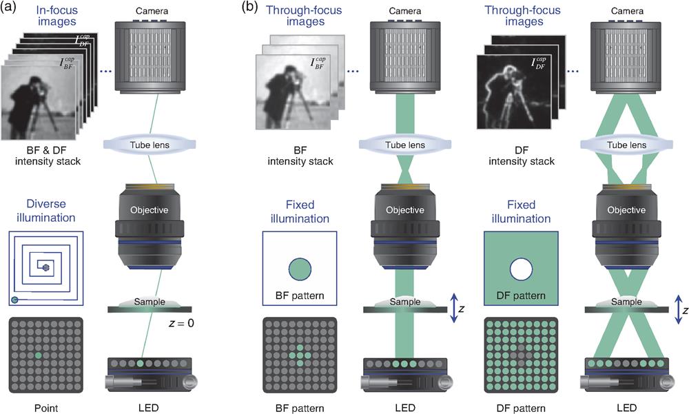
In the actual measurement of the intensity image, the dynamic range of BF and DF intensity images differs by several orders of magnitude, and the signal-to-noise ratio (SNR) between corresponding intensity images is quite different as well.30,31 Thus, the intensity images are separately captured under these two illuminations for better SNR and the capture process takes full advantage of the detector dynamic range, as illustrated in Fig. 1(b). It is worth mentioning that acquiring three sets (or more) of data according to the illumination NA can further effectively enhance the imaging SNR. But considering that the difference in the dynamic range of DF images with different NAs is much smaller than that in the BF case, the improved SNR performance of this strategy is relatively limited and increases the complexity of data acquisition. Hence, the proposed HBDTI captures only two sets of through-focus intensity stacks in BF and DF for the tradeoff of SNR and acquisition efficiency. The utilization of through-focus in TIE-based QPI is a traditional approach to introducing the imaginary component of the optical transfer function for improving phase effect, thereby the phase information can be transferred into the defocused intensity images.23,32 Based on the above considerations, we capture two through-focus intensity stacks under BF and DF illuminations as the inputs of the convergent iterative process for solving the nonlinear image formation of HBDTI.
![]()
Figure 1.Schematic diagram of the optical system comparison corresponding to the traditional FPM method and the proposed HBDTI method. (a) FPM requires a variably illuminated in-focus intensity stack that is captured under point illuminations. (b) HBDTI captures two through-focus intensity stacks under the discrete circle (BF) and the complementary-shaped (DF) illuminations, respectively.
To illustrate the advantages of HBDTI from the perspective of optical principle, we compared the optical system of the traditional FPM method and that of the proposed HBDTI method, as shown in Fig. 1. According to Fig. 1(a), FPM requires a variably illuminated in-focus intensity stack ( frames) with both BF and DF intensity images,33
We implement the HBDTI recovery algorithm by measuring two sets of through-focus intensity stacks and corresponding to the BF and DF illuminations [Fig. 2(a)], where is the defocus distance and is the step size of the intensity stack. As shown in step 2 in Fig. 2(b), the captured in-focus intensity is upsampled for the initialization of the object complex amplitude . Then, a series of high-resolution defocused intensity stacks are obtained through numerical propagation under corresponding LED illumination angles [step 3 in Fig. 2(c)], and the calculated low-resolution intensities after the downsampling of pixel binning can be treated as the input of the following intensity constraints process. In step 4 [Fig. 2(d)], the intensity images under different illumination angles are summed up to form the two intensity stacks and under corresponding BF and DF illuminations by coherent mode decomposition.34,39,40 The measured intensity stacks are divided by the two stacks as the factor to update the complex amplitude corresponding to various defocus distances. Inspired by the strategy of FPM,33 we apply the schemes of synthetic aperture and multiplexing to the difference map [step 5 in Fig. 2(e)],41
![]()
Figure 2.Roadmap of the proposed HBDTI method. (a) BF and DF defocused intensity stacks are measured under BF and DF illumination provided by
It is worth mentioning that the HBDTI method proposed in this paper is different from traditional FPM.33,35,36 In FPM, it requires a variable-illuminated intensity stack ( frames) including DF features at the in-focus plane under point illumination (leading to low-SNR intensity).33,45 Incorporating ptychographic phase retrieval and coherent synthetic aperture, FPM allows high-SBP imaging beyond the incoherent diffraction limit. But in terms of the matched illumination condition,37 FPM recovers low-frequency components only if the illumination angles match the cutoff angle allowed by the objective pupil function. Differently, HBDTI captures two through-focus intensity stacks ( frames) under BF and DF illumination with discrete circular and complementary-shaped patterns for high-SNR intensity. By merging synthetic aperture and multiplexed illumination,46 the achievable resolution of HBDTI can exceed the incoherent diffraction limit for high-SBP imaging. In contrast to FPM, as a propagation-based phase recovery method, the low-frequency phase components of HBDTI can be completely transferred by -scanning. Accordingly, HBDTI bypasses the strict requirement of the matched illumination condition by through-focus scanning, avoiding the loss of low-frequency components.38 Therefore, HBDTI can achieve the same high-SBP reconstruction capability as FPM only based on simpler operation and a smaller amount of data without the need for the matched illumination condition.
3 Results and Discussion
We perform the simulation under the 632 nm wavelength LED illumination with a pixel size detector and the , 0.1 NA objective to verify the feasibility of the proposed HBDTI approach. The simulated LED array of 120 mm below the sample is shown in Fig. 3(b), with a 6.5 mm distance between adjacent units. The original low-resolution data were defined with resolution, and the recovered high-resolution intensity was calculated in iteration number . As illustrated in Fig. 3(c), the details in the simulated low-resolution intensity image were severely blurred due to pixel binning. The HBDTI retrieval result in Fig. 3(d) presents more features than that in Fig. 3(c), such as the folds of clothes and the sideburns of the cameraman.
![]()
Figure 3.Quantitative simulation results by using HBDTI. (a1) Cameraman image with
Moreover, the high-throughput microscopy capability of HBDTI was validated by measuring the USAF resolution target, blood smear, and unlabeled Henrietta Lacks (HeLa) cells (both quantitative absorption and phase distributions) displayed in Figs. 4–6. The experiments were implemented on a commercial microscope (IX83, Olympus, Japan) that was equipped with a , 0.16 NA objective (PLN, Olympus, Japan) utilizing a motorized focus drive with a minimum step size of 10 nm, an industrial camera (The Imaging Source DMK33UX183, pixel resolution , pixel pitch ) and a programmable LED array. Each LED (RS-1515MBAM, Nationstar) approximately consumes 40 mW of power and provides spatially coherent quasimonochromatic illumination through three individual channels (central wavelength red 632 nm, green 504 nm, blue 460 nm, and bandwidth). The LED array is driven by a self-developed circuit with a field programmable gate array (FPGA) unit (EP4CE10E22C8N, Intel FPGA, United States) to provide logical control. The central LED array with a distance of 2 mm between adjacent units was placed 12.3 mm above the sample, offering the largest effective (in the case of BF illumination, ). In the experiments, in total, 100 intensity frames are acquired within a 3D intensity set () for 50 axial -slices under BF and DF illuminations achieved by a LED array within 5.5 s acquisition time (55 ms exposure time for each frame under objective lens). To improve computational efficiency, we adopt a nonmechanical image stitching algorithm of image segment recombination to reduce computational cost. Thus, in a normal laptop without GPU acceleration, our proposed method takes at ten iterations for 100 intensity images in the experiments.
![]()
Figure 4.High-throughput imaging results of USAF absorption target. (a1) Setup of HBDTI system based on a commercial microscope equipped with a programmable LED source at the front-end of illumination and a drive mechanism at the back-end of acquisition. (a2) The low-resolution BF in-focus intensity image of USAF was captured under a large FOV of
![]()
Figure 5.Imaging results of the stained blood smear. (a) BF low-resolution in-focus color image of stained blood cells. (b1) and (b2) BF and DF low-resolution in-focus intensity images of area 1 in (a). (b3), (c1), and (d1) The intensity images recovered by HBDTI in areas 1, 2, and 3 via summing the high-resolution HBDTI intensity results acquired separately for each of the three channels (
![]()
Figure 6.QPI results of unlabeled HeLa cells (as the phase object). (a) The retrieval full-FOV label-free HeLa cells phase result using the HBDTI method shows approximately 4000 HeLa cells on a
To demonstrate the throughput of HBDTI, the 1951 USAF resolution target (Ready Optics Company, United States) was captured with a , 0.16 NA objective under illumination as illustrated in Fig. 4. According to Sec. 3 in the Supplementary Material, the two sets of -axis intensity stacks were measured in under BF and DF illuminations. For the measured in-focus intensity shown in Fig. 4(a2), the highest distinguishable resolution target bars were element 5 in group 8 [Fig. 4(b1), half-pitch resolution]. Compared with the measured BF intensity and the quantitative profile in Figs. 4(b1) and 4(c1), all the unit details of group 8 were resolved in the HBDTI recovery result in higher contrast shown in Figs. 4(b2) and 4(c2). As depicted in Fig. 4(b2), the highest resolvable target bars of HBDTI retrieval result were element 1 in group 10, with a half-pitch resolution of . The maximum resolution of the experimental result presented the success of HBDTI to retrieve high-frequency features consistent with the theoretical half-pitch resolution of , .47 It was validated that HBDTI achieved high-resolution imaging of higher than the incoherent diffraction limit in the 0.16 NA objective, and the corresponding SBP was up to 30.2 megapixels with improvement under the FOV of .
HBDTI quantitatively recovers both phase and amplitude easily using two sets of defocused intensity stacks, which was confirmed by measuring the blood smear (Carolina Biological Supply Company, Burlington, North Carolina, United States) based on the , 0.16 NA objective (see Fig. 5 and Video 1). The low-resolution BF in-focus intensity shown in Fig. 5(a) was combined by the intensity images captured under quasimonochromatic illumination at (red), 504 nm (green), and 460 nm (blue), respectively. Applying the same experimental and computational parameters as the first experiment, the blurred edges and missing details of the blood cells in Fig. 5(b1) were retrieved using the proposed HBDTI method [Fig. 5(b3)]. Compared with the quantitative distribution in the measured intensity [Fig. 5(e1)], the profile of the blood cell was resolved clearly in the HBDTI recovery result both in intensity and phase [Figs. 5(e2) and 5(e3)]. In addition, as shown in Figs. 5(c1)–5(d2), the sharp red blood cells boundaries and the clear white blood cells’ internal particles were distinguished under a large FOV containing cells [Fig. 5(a)],48 proving the capability of HBDTI for precise detections of subcellular structures across the submicron scale to millimeter scale.
Our technique visualizes and provides high-resolution phase delay quantification of the unstained HeLa cells as the phase object, which was proved under the , 0.16 NA objective with illumination (see Fig. 6 and Video 2). HeLa cells were seeded (at an initial density of ) in a 35 mm glass-bottom Petri dish (No.0 Uncoated Coverslip, 10 mm Glass Diameter, MatTek Corporation, P35G010C) using DMEM high glucose with pyruvate (4.5 g 1:1 glucose, with GlutaMAX supplement, Gibco, Thermo Fisher Scientific or Roti-CELL DMEM, Roth) supplemented with 10% fetal bovine serum and penicillin-streptomycin (both Gibco, Thermo Fisher Scientific). Cells were incubated at 37°C in a humidified atmosphere of 5% carbon dioxide for 8 h to allow attachment. After that, cells were fixed in phosphate-buffered saline (PBS) buffer () on a microscope slide to preserve the cell morphology. According to Sec. 3 in the Supplementary Material, the two sets of -axis intensity stacks were also measured in under BF and DF illuminations. We adopted a nonmechanical image stitching algorithm of image segment recombination to reduce computational costs.33 As illustrated in Fig. 6(a), about 4000 HeLa cells with subcellular details were observed in the HBDTI recovery phase under a large FOV of . For better visual effects, we normalized the dynamic display range of the BF intensity and DF intensity, respectively. As shown in Figs. 6(b1) and 6(b2) and Figs. 6(c1) and 6(c2), it was confirmed that the intensity images acquired by HBDTI based on the taking full advantage of the detector dynamic range have a high SNR. As shown in Figs. 6(b3) and 6(c3), because of the low spatial coherence of circle-shaped BF illumination, TIE retrieved blurred cell boundaries and subcellular details with low contrast. Meanwhile, the missing details in the TIE retrieval results were accurately recovered by utilizing the proposed HBDTI approach in a wide FOV [Figs. 6(b4) and 6(c4)], achieving noninvasive high-throughput imaging for the high-content analysis of subcellular structure detections.
4 Conclusion
We have proposed a hybrid BF and DF transport of intensity approach for high-throughput QPI called HBDTI to solve the dilemma between the resolution and FOV. HBDTI extends the achievable imaging resolution beyond the incoherent diffraction limit via solving the nonlinear phase recovery problem under DF illumination, which is difficult for the linear formula of TIE. Utilizing two through-focus intensity stacks under BF and DF illuminations as input, HBDTI solves the nonlinear DF image formation model based on the coherent mode decomposition, which provides high-resolution recovery exceeding the incoherent diffraction limit in a large FOV. The successful performance of HBDTI has been demonstrated by the recovery of the USAF absorption target and biological specimens both with absorption and phase or pure phase. The experimental results have verified that the proposed HBDTI can achieve a wide FOV with a half-width resolution of 488 nm, achieving an improvement of in SBP from to . In the traditional TIE-based QPI method, whose illumination is limited in BF, its maximum attainable imaging resolution is at most 2NA. By combining BF with DF illuminations, the proposed HBDTI method has the capability to achieve the maximum resolution of about 5NA with a increase in the coherent diffraction limit. HBDTI shows the high-throughput ability to record large FOV images without degradation of the spatial resolution and has the potential in delineating subcellular structures in large-scale cell studies applicable for relatively thin objects. Further efforts, such as the differential collection of BF and DF images to relieve the data requirement and reduce the capturing time, are needed to promote the high-speed implementation of HBDTI in large-group live cell analysis.
Linpeng Lu received her BE degree from Nanjing University of Science and Technology. She is a fourth-year PhD student at Nanjing University of Science and Technology. Her research interests include computational microscopy, phase retrieval, and quantitative phase imaging. She is a member of SPIE and Optica.
Jiaji Li is a postdoc at the School of Electronic and Optical Engineering, Nanjing University of Science and Technology. He received his PhD from Nanjing University of Science and Technology in 2020. He was a visiting PhD student at the Department of Electrical and Computer Engineering, Boston University, from 2018 to 2019. He is currently a member of the Smart Computational Imaging Laboratory. His research interests include phase imaging and diffraction tomographic imaging. He is a member of SPIE and Optica.
Yefeng Shu is pursuing his PhD at Nanjing University of Science and Technology. His research interests include super-resolution microscopy, phase retrieval, and computational imaging. He is a member of SPIE and Optica.
Jiasong Sun received his BS degree from Soochow University in 2012 and his PhD from Nanjing University of Science and Technology in 2019. He is now an associate professor at the Department of Electronic and Optical Engineering. His research interest focuses on computational imaging, phase retrieval, super-resolution microscopy, diffraction tomography, and optical imaging. He is a member of SPIE and Optica.
Jie Zhou received his BE degree and is pursuing his ME degree at Nanjing University of Science and Technology. His research interests include deep learning-based phase retrieval and super-resolution microscopy. He is a member of SPIE and Optica.
Edmund Y. Lam received his BS degree, his MS degree, and his PhD, all in electrical engineering from Stanford University, in 1995, 1996, and 2000, respectively. He was the 49th PhD graduate of Prof. Joseph W. Goodman. He is now a professor in electrical and electronic engineering, the Director of the Computer Engineering Program, and the Founding Director of the Imaging Systems Laboratory at the University of Hong Kong. A recipient of the IBM Faculty Award, he is also a fellow of Optica, SPIE, IEEE, IS&T, as well as the Hong Kong Institution of Engineers.
Qian Chen received his BS, MS, and PhD degrees from Nanjing University of Science and Technology. He is currently a professor and vice-principal at Nanjing University of Science and Technology. He has been selected as Changjiang Scholar Distinguished Professor. With broad research interests in photoelectric imaging and information processing, he has authored more than 200 journal papers. His research team develops novel technologies and systems for non-interferometric quantitative phase imaging and high-speed 3D sensing and imaging, with particular applications in national defense, industry, and bio-medicine. He is a member of SPIE and Optica.
Chao Zuo received his BE and PhD degrees from Nanjing University of Science and Technology (NJUST) in 2009 and 2014, respectively. He was a research assistant at the Centre for Optics and Lasers Engineering, Nanyang Technological University, from 2012 to 2013. He is now a professor at the Department of Electronic and Optical Engineering and principal investigator of the Smart Computational Imaging Laboratory, NJUST. He has broad research interests in computational imaging and high-speed 3D sensing and has authored over 160 peer-reviewed journal publications. He has been selected for the Natural Science Foundation of China for Excellent Young Scholars and the Outstanding Youth Foundation of Jiangsu Province, China. He is a senior member of SPIE and Optica.
References
[8] G. Popescu. Quantitative Phase Imaging of Cells and Tissues(2011).
[10] J. Mertz. Introduction to Optical Microscopy(2019).
[11] R. H. Webb. Confocal optical microscopy. Rep. Prog. Phys., 59, 427(1996).
[17] A. Barty et al. Quantitative optical phase microscopy. Opt. Lett., 23, 817-819(1998).
[19] C. Zuo et al. Transport of intensity equation: a tutorial. Opt. Laser. Eng., 135, 106187(2020).
[36] X. Chang, L. Bian, J. Zhang. Large-scale phase retrieval. eLight, 4, 4(2021).
[44] V. Elser. Phase retrieval by iterated projections. J. Opt. Soc. Am. A, 20, 40-55(2003).
[50] Y. Cotte et al. Marker-free phase nanoscopy. Nat. Photonics, 7, 113-117(2013).

Set citation alerts for the article
Please enter your email address
© Copyright 2018-2021 | Chinese Laser Press. All Rights Reserved 沪ICP备15018463号-20