
E. J. Harvey. A route to enhanced performance for the petawatt beamlines of the Orion laser facility[J]. High Power Laser Science and Engineering, 2022, 10(3): 03000e19
- High Power Laser Science and Engineering
- Vol. 10, Issue 3, 03000e19 (2022)
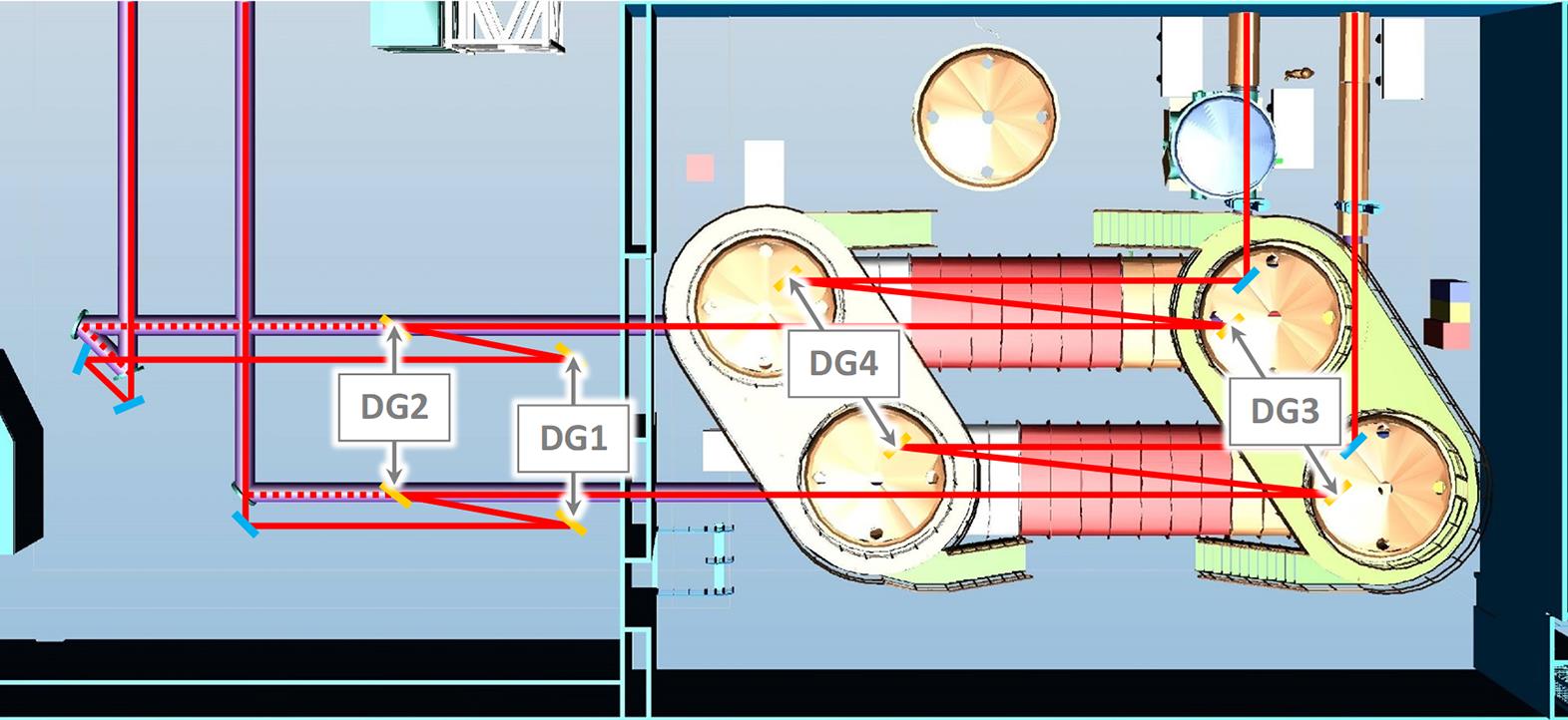
Fig. 1. Schematic layout (plan view) of the Laser Hall (left) and Compressor Hall (right), showing the new beam paths and components overlaid on the existing equipment. (Where they differ, the existing beam paths are shown with dashed lines.)
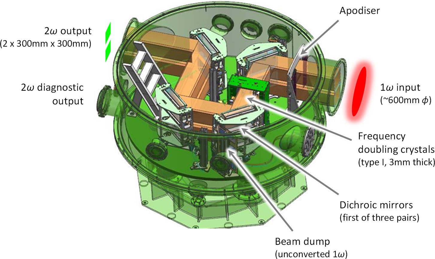
Fig. 2. Auxiliary vacuum chamber in its present configuration.
Fig. 3. Schematic layout (plan view) of the amended auxiliary chamber configured for the 2ω mode, for one beamline only, showing the incoming beam at 1ω (red) and the continuing beam at 2ω (green). The post-conversion grating pair (DG5, DG6) has been added and the final dichroic mirror in the chamber (DM3) has been repositioned as shown (compare Figure 2). To revert to the 1ω mode, the unnecessary apodizer (A) and mirrors (M1 and DM3) are removed, allowing the full aperture beam to propagate straight through the vessel.
Fig. 4. Expected performance on the target of the current and proposed configurations, showing pulse energy  and effective pulse duration of power
  on logarithmic scales. In the 2
ω mode, the basic scheme is illustrated with a representative set of configurations. Loci of fixed peak powers (in whole and half PW increments) are shown for reference.
and effective pulse duration of power on logarithmic scales. In the 2
| ||||||||||||||||||||||||||||||||||
Table 1. Draft specifications for 1ω diffraction gratings.
|
Table 2. Draft specifications for 2ω diffraction gratings.

Set citation alerts for the article
Please enter your email address
© Copyright 2018-2021 | Chinese Laser Press. All Rights Reserved 沪ICP备15018463号-20