
E. J. Harvey. A route to enhanced performance for the petawatt beamlines of the Orion laser facility[J]. High Power Laser Science and Engineering, 2022, 10(3): 03000e19
- High Power Laser Science and Engineering
- Vol. 10, Issue 3, 03000e19 (2022)
Abstract
1 Introduction
Orion[1], a high-power Nd:glass laser facility, commenced user experiments in 2013[2]. It provides ten beamlines with 0.1–10 ns pulse duration (‘long pulse’), each with a specification of 500 J in 1 ns at 351 nm and two beamlines each with a specification of 500 J in 500 fs (‘short pulse’) at 1054 nm. To obtain increased temporal contrast, one of the latter beamlines may be frequency doubled. With the original capability[3] enhanced recently, up to 210 J in 500 fs is available at 527 nm[4]. For a programme of experiments at high energy density, laser pulses are delivered to a small target, positioned and synchronized to high accuracy.
The study presented here considers significant enhancement of the performance of the ‘short pulse’ beamlines. Nominal specifications for operation at the fundamental level (1ω) have been proposed by the user community, requiring an increase in pulse energy on target to 1 kJ in each beamline in a duration reduced to 200–300 fs. The specification at the second harmonic (2ω) is to obtain as great a proportion of this pulse energy as reasonably practicable in a duration no greater than 1 ps.
A conceptual design has been developed that meets the specification with the minimum of modification to the existing beamlines. To deliver the second harmonic, a relatively straightforward approach is described. However, a novel, more developed approach with the potential to deliver similar energy in a much shorter pulse has also been devised. This route to high peak power at the second harmonic is not limited to the Orion facility and could be applicable generally.
Sign up for High Power Laser Science and Engineering TOC. Get the latest issue of High Power Laser Science and Engineering delivered right to you!Sign up now
Designs have been developed with the support of numerical simulation[5]. Details of the design and, for each mode of operation, an assessment of expected performance and critical specifications derived from it, are presented.
2 Conceptual design: operation at 1ω
2.1 Front end
At present, the front end consists of an oscillator, pulse stretchers and pre-amplifiers based on optical parametric amplification[1]. Spectral power in the output with a 20th-order super-Gaussian profile of 15 nm full width at half maximum (FWHM) has been assumed for the purposes of beamline design. It will be necessary to introduce an acousto-optic programmable dispersive filter (AOPDF) to achieve the shorter pulse duration required, through fine control of the spectral phase profile. No other modification of the front end is envisaged, except to amend the centre wavelength
2.2 Rod amplifier stage
Each beamline contains two rod amplifiers, which are passed twice. The two rods in each beamline differ, with one a phosphate glass (LHG-8) and the other a silicate glass (ED-2), to facilitate suitably broad bandwidth in the laser gain. While different options have been considered for reconfiguring the amplification in Nd:glass generally, requirements should be met without modifying the rod amplifier stage. The gain bandwidth may be increased sufficiently by increasing the contribution from the silicate rod amplifier. To be effective, however, this must be accompanied by a small change in the centre wavelength of sub-systems external to the laser amplifier, from 1054 to 1057 nm, so as to relax the impact of the upper bound on the wavelength that arises[1].
2.3 Disc amplifier stage
The aspiration to a pulse energy on a target of 1 kJ in each beamline informed the original design of the facility. A vacancy was included in order to accommodate an additional amplifier at 180 mm beam diameter. (Each amplifier contains three discs of LG-770.) Use of alternative glasses, such as variants of BLG-80[6], has been considered in the disc amplifiers, but no better compromise between output energy and bandwidth has been found.
Anticipating a change in the orientation of linear polarization, as dictated by the pulse compression (see below), the re-mounting of relevant components is expected, after rotation about the beam axis through a right angle.
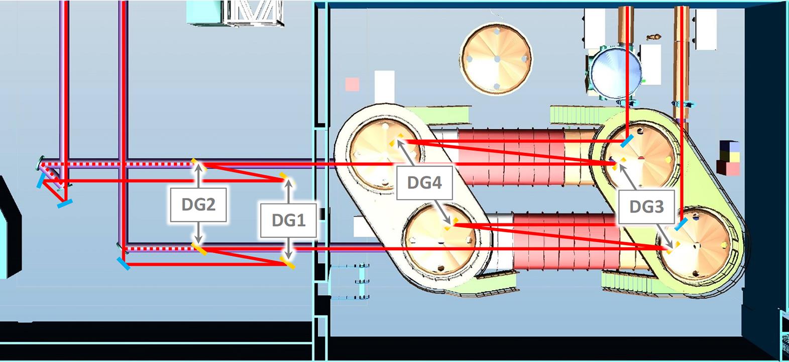
Figure 1.Schematic layout (plan view) of the Laser Hall (left) and Compressor Hall (right), showing the new beam paths and components overlaid on the existing equipment. (Where they differ, the existing beam paths are shown with dashed lines.)
Chromatic aberration (CA) in refractive singlet lenses, used routinely in beam transport, has a significant impact on beamline performance[7–9]. This will prevent achievement of the required pulse duration and it will be necessary to correct the aberration. The utility of diffractive components, which show axial CA of the opposite sign, has been recognized[10–12]. Such components are established as correctors of CA in high-power beamlines, such as PETAL[13] and OMEGA EP[14], and they are the favoured option for Orion. They might be introduced, as elsewhere, immediately prior to spatial filtering of the beam, at 180 mm diameter or possibly earlier, at 140 mm diameter, to provide for removal of small-scale phase error that may arise. While proprietary routes for manufacture are available, a collaborative programme of development is currently in progress that seeks to exploit in-house capability, enabling manufacture on site[15].
2.4 Pulse compression
At present, the pulse compression in each beamline consists of a single pair of reflection gratings. Owing to the limited threshold for laser-induced damage, it has long been understood that the gold coating represents the fundamental constraint on an increase in pulse energy. Multi-layer dielectric (MLD) gratings, which show a substantially increased damage threshold in the relevant range of pulse duration[16], are now available at large aperture. However, it is considered likely that otherwise like-for-like replacement is not available, with the groove profile implied at the current density (1480 mm–1)[1] not considered viable. In any event, increased bandwidth in the amplified pulse would enlarge the aperture required at the second grating and beyond, where the beam is laterally dispersed, to an extent that would not be cost-effective.
Therefore, the grating configuration must change. Given the high cost of replacement, the existing vacuum vessels shall be retained, fixing the geometry of the beams within. To resolve this situation, accommodating gratings of different groove density and a greater bandwidth, the pulse compression in each beamline is divided between two grating pairs in sequence (see Figure 1). The second (C2 = DG3, DG4) will be accommodated within one of the existing vacuum vessels, while the first (C1 = DG1, DG2) will precede it, located in space available in the Laser Hall and not evacuated. Support structures for the latter will be sufficiently robust to enable and retain alignment of the beamlines to the tolerances required. Separation into two differing grating pairs allows the new configuration to replicate the existing spectral phase change (to second and third derivatives, at least).
| Type | ||||||||
|---|---|---|---|---|---|---|---|---|
| Existing configuration | 1054 | Gold, p | 1480 | 47.9 | 54.9 | 940 | 13 | |
| Proposed | C1 | 1057 | MLD, s | 1568 | 52.2 | 60.1 | 1020 | 5.1 |
| configuration | C2 | 1300 | 47.0 | 40.0 | 910 | 13 | ||
Table 1. Draft specifications for 1
![]()
Figure 2.Auxiliary vacuum chamber in its present configuration.
The grating pair accommodated in the vacuum vessels (C2) must take a groove density smaller than the current value. The angle of incidence at DG3 must be comparable to the current value. If it is too small, the requirement for pulse energy cannot be met. If it is too large, the aperture of the gratings, already the largest components in the facility, becomes excessive. Together, these conditions restrict the range of practicable groove density to around 1150–1350 mm–1. They also imply that the angle of diffraction at DG3 is smaller than the angle of incidence, opposite to the current configuration of the pulse compression.
The additional grating pair in each beamline (C1) will be accommodated prior to the other as described above. Applying similar considerations, a higher groove density is implied and an angle of diffraction at DG1 that is larger than the angle of incidence.
The proposal is summarized in Table 1. Practicability is contingent on availability of efficient MLD gratings at these groove densities, but realistic designs have been established (see the Acknowledgement). In contrast to gold coating, they require s polarization. The laser-induced damage threshold required for each grating and the tolerances for misalignment have been determined (see the Appendix).
Although the complexity of the pulse compression is increased, a valuable benefit of multiple grating pairs is the option to oppose the lateral dispersions in order to reduce the effect overall. While the lateral dispersion in the compressed pulse is large at present (around 39 mm nm–1), in the proposed configuration it is all but eliminated, optimizing spatial filling at the critical final grating and beyond. Note that, in order to do this, the two pairs must be arranged so that the beam in each tracks laterally in the same direction (see Figure 1). This arrangement also reduces the sensitivity overall to input pointing/wavefront error, for a given pulse duration.
3 Conceptual design: operation at 2ω
Frequency doubling the compressed pulse in one of the beamlines is an important aspect of the facility capability. This is achieved in an auxiliary chamber separate from the compressor chambers (see Figure 2). However, an awkward feature of both the original installation[1,3] and the present installation, enhanced in aperture by segmentation with two beamlets 300 mm square in a vertical array[4], is the fact that the frequency doubling crystals are on the verge of being over-driven[9]. Increased input intensity would lead to de-conversion and loss of efficiency. This would arise if CA in the beamline were corrected[9], a realistic possibility in the near term in its own right[15], but much more so with the increased pulse energy and reduced pulse duration specified here for 1ω operation. In the latter case the likely consequence would be several cycles of conversion and de-conversion through the thickness of the crystals, and an unmanageable impact on laser performance.
Clearly, a thinner crystal would address this situation. Simulation suggests that converted pulse energy would be optimized at a reduced thickness of the order of 1 mm. While doubling of similar[17] or much higher intensities[18,19] in thin crystals has been investigated, no such component is available, or likely to become available in the near term, at the required aperture. Instead, we consider moderating the input intensity sufficiently to regain efficient conversion in available crystals.
This could be achieved simply by reducing the pulse energy, but this is clearly a poor strategy. As the input pulse would be shorter than at present by default, the converted pulse energy would inevitably fall below the current value.
Alternatively, we consider moderating the intensity at the crystals by controlling the temporal profile of the pulse (without significant loss). One obvious approach is to detune the otherwise well-compressed input pulse by mismatching the pulse stretchers and compressors. Unfortunately, while the pulse would then be longer and less intense, it would also be chirped, with a variation of instantaneous frequency through the pulse. Phase matching, which is achieved exactly at only one frequency (or a limited number of discrete frequencies), would therefore be compromised.
Fortunately, type I doubling near 1057 nm in potassium dihydrogen phosphate (KDP) shows group velocities for the coupled waves that nearly match at the phase-matching angle. Not only does this provide proof against loss of temporal overlap during conversion, but it also renders the phase-matching angle much less sensitive to frequency. This implies resistance to chirp, with the pulse phase matched relatively well over the whole bandwidth.
3.1 Basic scheme
For a given energy at the fundamental, there will be a corresponding detuning required to moderate the intensity at the crystals sufficiently to restore efficient conversion. The range of pulse duration permitted by the specification (up to 1 ps at 2ω) allows a generous upper bound on the energy that can be utilized (see below). Just as importantly, it appears that the necessary detuning can be introduced without the accompanying chirp compromising the conversion process. In fact, still greater chirp appears to be acceptable.
This approach has the advantage of leaving the post-compressor beamlines unchanged. On the other hand, it is unlikely to offer a meaningful increase in peak power, able to deliver increased energy only in a longer pulse. (It is compatible with enlargement of the aperture, segmented with a 2×2 array of beamlets, for example, although the further uplift in pulse energy would be accompanied by some degradation of temporal contrast on the target. The elimination of lateral dispersion in the compressed pulse precludes the softening of spectral clipping in the compressor otherwise derived from the roll-off to the periphery of the uncompressed spatial profile[1]. The consequent degradation of temporal contrast is strongest in the parts of the aperture that are peripheral in the dispersion direction.)
3.2 Advanced scheme
There is a further option for the moderation of intensity at the frequency doubling crystals in which a detuned pulse, having been frequency doubled, might then be compressed fully. This contrasts with a scheme in which a well-compressed pulse is doubled in a thin crystal, and its temporal profile is re-optimized subsequently after spectral amplitude and phase distortion in the crystal[17–19].
A further grating pair (C3 = DG5, DG6) is anticipated (see Figure 3). This is expected to be segmented as for the other optics in the auxiliary chamber. Other reflective components, such as multi-layer chirped mirrors or Gires–Tournois interferometers[20], are unlikely to supply sufficient chirp. Assuming a familiar z-fold involving the first diffracted order accommodated in a (replaced) auxiliary vacuum chamber, the grating separation is limited to around 720 mm and the angle made between the incoming and outgoing beams at each grating may be in excess of 30°. The latter is far from ideal in typical circumstances, but efficient gratings will be assumed for the present. With the layout fixed, the groove density and angle of incidence are in a fixed relationship, effectively a single free parameter. In view of the limited flexibility, some assistance will be needed from the enhanced front end in the form of further fine adjustment of the spectral phase.
While only a relatively small chirp is needed to moderate the intensity sufficiently for the existing crystals, this leaves a problem for the post-conversion compressor. With the geometry constrained, the modest compression required implies a low groove density of 500–600 mm–1. At the reduced wavelength of the second harmonic, such gratings admit multiple diffracted orders and an efficient grating design is unlikely. To avoid this situation, the groove density, and with it the chirp at the crystals, must be increased significantly. Based on a fixed angle between beams at the gratings of
![]()
Figure 3.Schematic layout (plan view) of the amended auxiliary chamber configured for the 2
| Type | ||||||
|---|---|---|---|---|---|---|
| 528.5 | MLD, p | 1610 | 43.2 | 9.5 | 440 | 0.721 |
Table 2. Draft specifications for 2
Frequency doubling is desirable as it enhances the temporal contrast of the compressed pulse significantly[1–3]. Introducing diffraction gratings post-conversion has the potential to degrade the contrast through scattering. The extent of this effect is not easy to predict. On the other hand, it should be noted that the zero order at DG5 will be rejected spatially, passing out of the beamline. This enhances the removal of unconverted light, handled currently with dichroic mirrors alone[4].
With the intended configuration established, an immediate concern is the availability of a design for efficient gratings. As it will be highly desirable to retain all gratings in a vertical plane, use of s polarization at 1ω gratings and type I doubling implies p polarization at 2ω gratings. Fortunately, investigation suggests that a favourable, if somewhat demanding, design exists for p polarization (see the Acknowledgement). The laser-induced damage threshold required for each grating and the tolerances for misalignment have been determined (see the Appendix).
For fine alignment of a parallel grating pair, angular dispersion in the transmitted beam can be used as a diagnostic of misalignment. This can be observed using a broadband beam brought to focus. At present, the front end produces broadband pulses at a repetition rate of 2 Hz, which are sufficiently energetic after frequency doubling in the auxiliary chamber to be detectable at focus at the target position[4]. This can continue in the advanced configuration if the pulse compression at the fundamental is re-optimized temporarily, as for operation in the 1ω mode. While the converted pulse will be chirped subsequently by C3, this is inconsequential for time-integrated observation.
Although the design is beyond the scope of this paper, diagnostics of the performance in the 2ω mode will be provided.
Finally, it is necessary to consider the adjustment to the front end required in switching to the 2ω mode. Various options are available. (i) The simplest requires an increase in the single-pass equivalent grating separation in the pulse stretcher
4 Expected performance
Performance of the beamlines at full power has been simulated. Wavefront error from optical components and the effect of spatial filtering have been neglected for simplicity. Background effects, such as amplified spontaneous emission (ASE), are not included. The spectral variation of diffraction efficiency has been represented in all cases. Pulse durations are rendered hereafter as effective values, that is, the integrated value of a temporal profile divided by its peak value, rather than the FWHM.
The bandwidths of spectral power expected immediately before and after the 1ω compressor are 7.9 and 7.7 nm, respectively (FWHM), and 8.2 and 8.0 nm, respectively (effective value).
Expected performance on the target is summarized in Figure 4. For comparison, this includes the beamlines in their current configuration, and the correction of CA as an intermediate step. While each beamline will continue to benefit from a deformable mirror in the disc amplifier stage[1], diffraction-limited performance on the target cannot be assured.
![]()
Figure 4.Expected performance on the target of the current and proposed configurations, showing pulse energy  and effective pulse duration of power
  on logarithmic scales. In the 2
In the 1ω mode, some 1070 J in 290 fs (3.7 PW and up to
In the 2ω mode, performance depends on which option has been selected. (i) In the basic scheme, the change in effective stretcher grating separation
5 Conclusions
Enhancement of the Orion laser facility has been considered and a conceptual design for modification of the ‘short pulse’ beamlines has been described. This meets the proposed specification, with operability expected to remain within reasonable bounds.
The expected performance represents a substantial uplift in capability, especially if the advanced scheme for the second harmonic is implemented. Although the practicability of critical components is not yet confirmed, this scheme is potentially applicable quite generally. It offers a route to ultra-high power at the second harmonic, with the accompanying advantage of high temporal contrast.
References
[1] N. W. Hopps, K. Oades, J. Andrew, C. Brown, G. Cooper, C. Danson, S. Daykin, S. Duffield, R. Edwards, D. Egan, S. Elsmere, S. Gales, M. Girling, E. Gumbrell, E. Harvey, D. Hillier, D. Hoarty, C. Horsfield, S. James, A. Leatherland, S. Masoero, A. Meadowcroft, M. Norman, S. Parker, S. Rothman, M. Rubery, P. Treadwell, D. Winter, T. Bett. Plasma Phys. Control. Fusion, 57, 064002(2015).
[2] D. J. Hoarty, P. Allan, S. F. James, C. R. D. Brown, L. M. R. Hobbs, M. P. Hill, J. W. O. Harris, J. Morton, M. G. Brookes, R. Shepherd, J. Dunn, H. Chen, E. Von Marley, P. Beiersdorfer, H. K. Chung, R. W. Lee, G. Brown, J. Emig. High Energy Density Phys., 9, 661(2013).
[3] D. Hillier, C. Danson, S. Duffield, D. Egan, S. Elsmere, M. Girling, E. Harvey, N. Hopps, M. Norman, S. Parker, P. Treadwell, D. Winter, T. Bett. Appl. Opt., 52, 4258(2013).
[4] S. Parker, C. Danson, D. Egan, S. Elsmere, M. Girling, E. Harvey, D. Hillier, D. Hussey, S. Masoero, J. McLoughlin, R. Penman, P. Treadwell, D. Winter, N. Hopps. High Power Laser Sci. Eng., 6, e47(2018).
[5] E. J. HarveyProceedings of International Conference on Ultra-High Intensity Lasers. , in ().(2006).
[7] Z. Bor. J. Mod. Opt., 35, 1907(1988).
[8] E. J. Harveyω. , “Performance of the main short pulse beamlines of Orion at 1,” AWE Plasma Physics Department Annual Report (), p. ., 35(2006).
[9] E. J. Harvey. , “Physics design of the frequency doubling crystals for the main short pulse beamlines of Orion,” AWE Plasma Physics Department Annual Report (), p. ., 27(2007).
[10] Z. Bor. Opt. Lett., 14, 119(1989).
[11] H.-M. Heuck, P. Neumayer, T. Kühl, U. Wittrock. Appl. Phys. B, 84, 421(2006).
[12] J. Néauport, N. Blanchot, C. Rouyer, C. Sauteret. Appl. Opt., 46, 1568(2007).
[13] N. Blanchot, G. Behar, T. Berthier, E. Bignon, F. Boubault, C. Chappuis, H. Coïc, C. Damiens-Dupont, J. Ebrardt, Y. Gautheron, P. Gibert, O. Hartmann, E. Hugonnot, F. Laborde, D. Lebeaux, J. Luce, S. Montant, S. Noailles, J. Néauport, D. Raffestin, B. Remy, A. Roques, F. Sautarel, M. Sautet, C. Sauteret, C. Rouyer. Plasma Phys. Control. Fusion, 50, 124045(2008).
[14] D. N. Maywar, J. H. Kelly, L. J. Waxer, S. Morse, I. A. Begishev, J. Bromage, C. Dorrer, J. L. Edwards, L. Folnsbee, M. J. Guardalben, S. D. Jacobs, R. Jungquist, T. J. Kessler, R. W. Kidder, B. E. Kruschwitz, S. J. Loucks, J. R. Marciante, R. L. Mccrory, D. D. Meyerhofer, A. Okishev, J. B. Oliver, G. Pien, J. Qiao, J. Puth, A. Rigatti, A. W. Schmid, M. J. Shoup, C. Stoeckl, K. A. Thorp, J. Zuegel. J. Phys.: Conf. Ser., 112, 032007.
[15] E. J. Harvey, D. A. Egan, R. J. S. Aulsberry, S. J. WheelerInternational Conference on Ultra-High Intensity Lasers. , , , and , in ().(2018).
[16] J. Neauport, E. Lavastre, G. Razé, G. Dupuy, N. Bonod, M. Balas, G. de Villele, J. Flamand, S. Kaladgew, F. Desserouer. Opt. Express, 15, 12508(2007).
[17] S. Y. Mironov, J. Wheeler, R. Gonin, G. Cojocaru, R. Ungureanu, R. Banici, M. Serbanescu, R. Dabu, G. Mourou, E. A. Khazanov. Quantum Electron., 47, 173(2017).
[18] S. Mironov, V. Lozhkarev, V. Ginzburg, I. Yakovlev, G. Luchinin, E. Khazanov, A. Sergeev, G. Mourou. Proc. SPIE, 7721, 77211R(2010).
[19] S. Y. Mironov, V. V. Lozhkarev, V. N. Ginzburg, I. V. Yakovlev, G. Luchinin, A. Shaykin, E. A. Khazanov, A. Babin, E. Novikov, S. Fadeev, A. M. Sergeev, G. A. Mourou. IEEE J. Sel. Topics Quant. Electron., 18, 7(2012).
[20] J. Kuhl, J. Heppner. IEEE Trans. Quantum Electron., 22, 182(1986).
[21] S. Hocquet, J. Neauport, N. Bonod. Appl. Phys. Lett., 99, 061101(2011).

Set citation alerts for the article
Please enter your email address
© Copyright 2018-2021 | Chinese Laser Press. All Rights Reserved 沪ICP备15018463号-20