Ronghui Lin, Zahrah Alnakhli, Xiaohang Li. Engineering of multiple bound states in the continuum by latent representation of freeform structures[J]. Photonics Research, 2021, 9(4): B96
Copy Citation Text
We demonstrate a neural network capable of designing on-demand multiple symmetry-protected bound states in the continuum (BICs) in freeform structures with predefined symmetry. The latent representation of the freeform structures allows the tuning of the geometry in a differentiable, continuous way. We show the rich band inversion and accidental degeneracy in these freeform structures by interacting with the latent representation directly. Moreover, a high design accuracy is demonstrated for arbitrary control of multiple BIC frequencies by using a photonic property readout network to interpret the latent representation.
1. INTRODUCTION
The optical bound states in the continuum (BICs) refer to an exotic class of states that remain perfectly confined despite lying in a continuous spectrum of radiating waves [1,2]. The lack of outgoing radiation means these states have a theoretical infinite lifetime but are unable to be excited by far-field radiation. In practice, perturbations are introduced intentionally or unintentionally to turn the BICs into leaky resonances with finite albeit high factors [3]. Engineering these modes to leverage the high quality () factor is benefiting a wide range of applications such as lasers [4,5], sensors [6,7], and nonlinear optics [8,9].
Recent reports show the BICs arise from the vortex centers of the polarization field and they carry quantized topological charges [10]. Merging of multiple BIC points can be used to achieve robust ultra-high factor modes immune to out-of-plane scattering losses [11]. Moreover, being able to manipulate multiple BICs might further benefit areas where high factors are desirable at multiple frequencies such as nonlinear optics [12] and multi-wavelength sensing [13–15].
The core idea of realizing BICs is the parameter tuning to cancel out the far-field radiation. This is mostly achieved by the sweeping of parametric geometries such as circles, rectangles, ellipses, or the combination of them. These geometrics can be easily described and modified by equations with a limited number of variables and, thus, a limited degree of tunability. They run into problems with more advanced tuning tasks such as the manipulation of multiple BICs simultaneously. So far, arbitrary control of multiple BICs has never been achieved.
Sign up for Photonics Research TOC. Get the latest issue of Photonics Research delivered right to you!Sign up now
The freeform structures optimized by evolutionary algorithms [16,17] and adjoint methods [18,19] show great potential in the topology optimization of photonic structures and promise new methods of tuning BICs. They are not bound by any equations and, thus, offer a limitless degree of tunability, which may yield designs that outperform those by conventional geometries [19,20]. However, these algorithms are generally costly in computational resources. Besides these interactive optimization methods, deep neural networks (DNNs) are viable tools in handling complicated photonic structures [20–22]. There have been some impressive attempts to design freeform photonic structures using generative adversarial networks (GANs) [23–27]. A problem with the GANs is the difficulty in training with the possibility of noisy outputs where extra filtering and smoothing algorithms are needed to refine the geometries [24,25]. Another issue with the GANs is that the desired optical properties are directly linked to the geometrical shapes described by pixels, which have much higher dimensions than that of the optical properties such as the transmission and reflection spectra. This results in converging problems and bad generalization performance. Furthermore, the structures with predefined symmetries, which are a critical quality in the field of photonics, have not been demonstrated by GANs. To make the DNNs learn and generate the symmetry and parity properties of the real-life structures is an active research topic in the machine learning community [28–30]. Special techniques such as symmetry loss [31] and structured GANs [32] are necessary to ensure symmetrical outputs. In this work, we demonstrate a DNN structure based on the variational autoencoders (VAEs) that can handle freeform photonic structures with predefined symmetry. Instead of connecting the property to the pixel representation of the geometries directly, we convert the geometries into the latent representation, which can be linked to the optical properties more easily and, hence, increase the stability of the inverse design. The latent representation also allows small perturbations of the geometries, which in turn allow continuous manipulation of the photonic properties. With a property readout network to interpret the latent representation, we demonstrate arbitrary, on-demand control of multiple BICs with high accuracy. The band inversion and accidental degeneracy arising from these symmetrical freeform structures can also be a platform for further discoveries and innovations.
2. SYMMETRY-PROTECTED BIC IN C4v Lattice
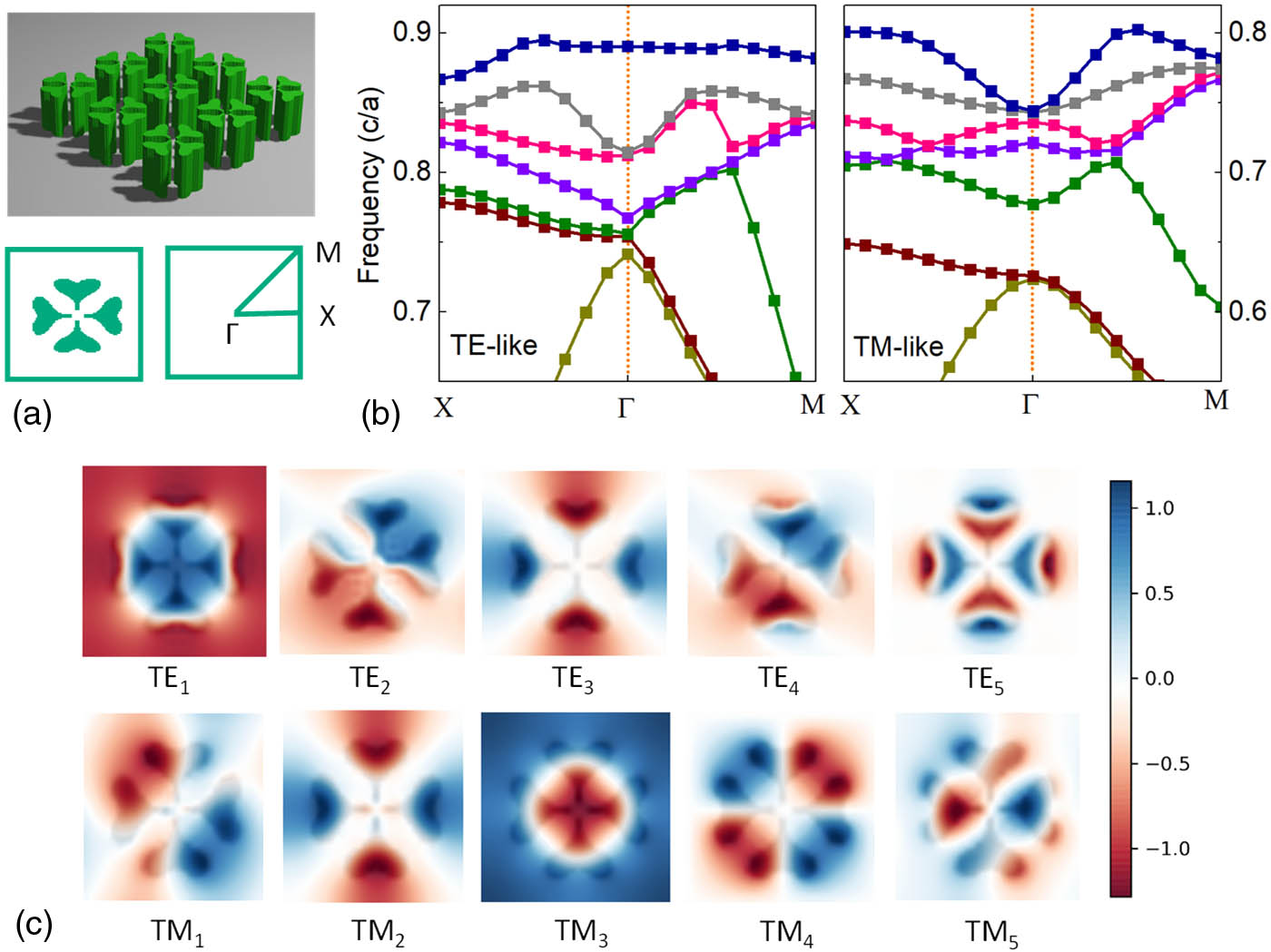
Figure 1.(a) Top, an artistic rendering of the photonic crystal considered. Bottom, planar view of the unit cell and the definition of high symmetry points. (b) Band diagram for TE-like and TM-like modes. (c) and Bloch mode profiles for TE-like and TM-like modes, respectively.
Since these BICs are protected by symmetry, their frequencies can be tuned by geometrical perturbations as long as the symmetry is maintained. The freeform structure with symmetry as shown in Fig. 1(a) is studied. We consider a unit cell of with the material refractive index , which corresponds to Si in the infrared region. The geometry is assumed to have a fixed height of 550 nm in the air with a mirror symmetry about the plane. Hence, the photonic modes can be classified as TE- and TM-like modes. The unit cell is discretized with a mesh, and the plane wave expansion method is used to determine the eigenmodes and eigenfrequencies along the high symmetry points . The calculations are implemented with an open-source package MIT photonic bands (MPB) [33]. The photonic band diagrams and the corresponding Bloch mode profiles are shown in Figs. 1(b) and 1(c). The field is plotted for TE-like modes, and the field is plotted for TM-like modes. The , , , and are doubly degenerate modes, as can be verified from the band diagrams. These mode profiles have an odd parity for transformation. The nondegenerate modes are all even modes for transformation, and they all lie below the diffraction limit , where , , and are the speed of light, the refractive index of air, and the lattice size, respectively. Hence, they are all symmetry-protected BIC modes. The Bloch modes of the freeform structures largely resemble the field profiles of Mie-type resonators. However, they are distorted and deformed with a lot of local features, which are the key to engineer and fine-tune the BIC frequencies.
Figure 2.(a) Transmission spectra at different incident angles for s polarization and p polarization. The red arrows indicate the doubly degenerate modes, and the numbered modes are nondegenerate. (b) The factors of the BIC modes shown in (a).
We use the -VAE [34,35] with a loss function as follows: The first term is the reconstruction loss, which forces the decoder to represent the input as closely as possible. The second term is the Kullback–Leibler (KL) divergence between the prior distribution and the encoder distribution . It is a regularization term that forces the latent representation to assume the same standard normal distribution as the prior . The resultant latent representation is centered and closely packed in the latent space, and most importantly, continuous and interpolable. The factor imposes extra weight on the KL divergence, thus increasing the regularization power. Previous reports show an increase in the factor can promote the disentanglement of latent representation [35], allowing them to be more interpretable. In this work, we choose a factor of 3. The -VAE can not only reproduce the training data but also create new data with the same distribution as the training data. As the high dimension data are collapsed to a lower dimension, a lot of the high dimension features and minor details are filtered out. Hence, the output geometries are naturally smooth with less ultrafine structures such as sharp corners and isolated islands. Moreover, the latent representation has similar dimensions with our optical response, which is easier to link to the optical properties by DNN.
We use 20,000 randomly generated geometries with symmetry to train the -VAE. The training geometries are generated by applying symmetry operations to random polygons. The training loss of the -VAE in Fig. 3(b) shows good convergence, which is an advantage over GANs. Randomly generated latent vectors are used to test the output of the -VAE after the training. Some examples of the output are shown in Fig. 3(c). The VAE can produce a wide variety of geometries with different topology while maintaining the perfect symmetry. These geometries are obtained without any additional filtering, but they are smooth with little noise. Since the latent representation is continuous, a perturbation of the latent vector results in a perturbation in the output. This is demonstrated in Visualization 1, where we show the change of the output geometries as the vector is varied continuously.
Figure 4.(a) Shapes of geometry 8 and 12, with the sites of deformation marked by red arrows. (b) The shift of TE-like and TM-like bands at point as the latent vector is varied continuously (see Visualization 1 for the continuous variation of the geometries). (c) field of TE-like modes for geometry 12. The inversed bands are grouped by dashed green boxes.
The reason for this band crossing can be understood from the Bloch mode profiles. In Fig. 4(c), the field of is mostly localized at the center of the heart-shaped structures; hence, it is less sensitive as the heart shape deforms. In contrast, is more susceptible to such changes because a considerable amount of field intensity is located at the site of deformation. Since the amount of the frequency shift is proportional to the field concentration in the perturbation area [41], the band remains mostly unchanged while the band shifts more drastically, causing the band crossing. In this geometry, , , and are symmetry-protected BICs. The shifting and crossing of the bands give us a lot of possible combinations of BICs. Since these shapes are controlled by a latent vector with 10 dimensions, there are 10 dimensions to fine-tune the geometries and, hence, the BIC combinations.
Figure 5.(a) Shift of TE-like and TM-like bands at point as the scaling factor is varied. The inset in (a) shows the geometry considered. (b) The field of TM-like modes for geometry with a scaling factor of 0.8. The inversed bands are grouped by dashed green boxes.
Figure 6.(a) Whole DNN structure studied in this work. (b) Information flow during training, where 1 is the training of -VAE, 2 is the training of , and 3 is the training of . (c) Information flow for the forward modeling and the inverse design.
Figure 8.(a) Correlation between target BIC wavelengths in the validation data set and the output of the DNN. (b) Correlation between randomly generated target BIC wavelengths and the output of the DNN. The axis is the target value, and the axis is the DNN output in both (a) and (b).
Figure 9.Demonstration of the multiple BIC inverse design. (a) The comparison of the random target BIC wavelengths, DNN output, and numerical simulation. The inset shows the output geometry of the DNN. (b) Band diagrams for the designed structures. (c) The and field profiles for the TE and TM BIC states, respectively.
We demonstrate a DNN structure that can design and engineer multiple symmetry-protected BICs by manipulating freeform structures with predefined symmetry. The geometries are represented by latent vectors, which can then be mapped to the photonic property by a property readout network. We demonstrate the on-demand design of three arbitrary BIC frequencies with high accuracy. We also analyze the nature of complicated band inverse and accidental degeneracy when such freeform structures are tuned and scaled continuously, which shows the potential for further discovery and application.
Acknowledgment
Acknowledgment. The authors would like to thank Prof. Andrea Fratalocchi from KAUST for his advice.
References
[10] B. Zhen, C. W. Hsu, L. Lu, A. D. Stone, M. Soljačić. Topological nature of optical bound states in the continuum. Phys. Rev. Lett., 113, 257401(2014).
Ronghui Lin, Zahrah Alnakhli, Xiaohang Li. Engineering of multiple bound states in the continuum by latent representation of freeform structures[J]. Photonics Research, 2021, 9(4): B96