
Junmin ZHANG, Xiaowu CHEN, Chunjin LIAO, Feiyu GUO, Jinshan YANG, Xiangyu ZHANG, Shaoming DONG. Optimizing Microstructure and Properties of SiCf/SiC Composites Prepared by Reactive Melt Infiltration [J]. Journal of Inorganic Materials, 2021, 36(10): 1103
- Journal of Inorganic Materials
- Vol. 36, Issue 10, 1103 (2021)
Abstract
Keywords
Due to obvious advantages of fast densification and low cost, reactive melt infiltration (RMI) has become one of the most attractive techniques in the fabrication of ceramic and ceramic-matrix composites[
Research proved that melt infiltration kinetics is strongly dependent on the pore structure of preforms[
In addition to pore closure, inhomogeneity of pore structure is another important factor affecting the melt infiltration. As for fibrous preforms prepared based on woven fiber bundles, where inter-bundle pores are usually much larger than intra-bundle pores, uniform melt infiltration is hardly realized due to the inhomogeneous pore structure[
In present study, SiC fibrous preforms were prepared by slurry impregnation(SI), and the pore structure was adjusted through different impregnation treatments. The effects of pore structure on the melt infiltration and the as-received SiCf/SiC composites were studied in detail. Compared to phenolic resin impregnation, the preform obtained by polymer blend (organic pore former+phenolic resin) impregnation showed more homogenous pore structure and more sufficient Si melt infiltration, thus resulting in better mechanical properties of the composites. Besides, the infiltration kinetics in terms of pore struc- ture was investigated mathematically, which further con-firms that the infiltration is controlled by pore structure. This study can provide guidance for optimizing RMI- derived composites by pore structure adjustment.
1 Experimental procedure
1.1 Materials and process
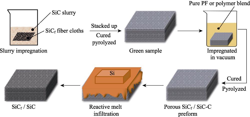
A schematic of material preparation is given in Fig. 1. Firstly, plain-weave KD-Ⅱ SiC fiber cloths (National University of Defense Technology, China) was coated with BN interphase (~500 nm thick) via chemical vapor infiltration (CVI) method. SiC slurry prepared by mixing SiC powders was impregnated into SiC fiber cloths by vacuum impregnation. The preparation technology of the slurry is similar with the previous study[
![]()
Figure .Flowchart of SiCf/SiC composites fabrication process
To obtain preforms with various pore structures, different impregnation treatments were used to adjust the pore structure. The pyrolyzed preforms were divided to three groups: the first group, named Pre-1, was directly densified by RMI without further impregnation, the second group, named Pre-2, was impregnated with phenolic resin (PF; 2130#, Wuxi Guangming Chemical Co. Ltd., Wuxi, China), and the third group was impregnated with a polymer blend of named Pre-3, in which the ratio of organic pore former/PF was 0.2. Then the re-impregnated preforms were cured at 130 ℃, followed by pyrolysis in flowing Ar atmosphere at 900 ℃. Finally, Si melt was infiltrated into the preforms at 1490 ℃ to obtain SiCf/ SiC composites. The designations of the preforms and the composites are shown in Table 1.
| Preform | Preparing process | Further impregnation | Composites |
|---|---|---|---|
| Pre-1 | Slurry impregnation | None | Com-1 |
| Pre-2 | Slurry impregnation | Pure PF | Com-2 |
| Pre-3 | Slurry impregnation | Polymer blend | Com-3 |
Table 1.
Different impregnation treatments to the preforms
1.2 Tests and characterization
The pore size distribution of the preforms and the porous carbon derived from PF and the polymer blend of organic pore former+PF were analyzed using an AutoPoreIV 9510 mercury porosimeter (Micromeritics, Shanghai, China). The phase compositions of the preforms and the composites were analyzed by a Rigaku D/max X-ray diffractometer (XRD, Rigaku Corporation, Kyoto, Japan) with monochromated Cu-Kα radiation (40 kV, 40 mA, 10 (°)·min-1 from 10° to 80°). The microstructures of the preforms and the composites were observed using an S4800 field emission scanning electron microscope (FESEM, Hitachi, Tokyo, Japan). The elemental analyses were conducted by energy dispersive spectroscope (EDS, Aztec X-Max 20, Oxford, UK).
The bulk density and open porosity of the preforms and the composites were measured by Archimedes method using deionized water as an immersing medium. To evaluate the effects of the preform pore structure on the mechanical properties of the composites, room temperature flexural strength of the composites was determined on specimens with average size of 3 mm×5 mm×40 mm, using a 3-point bending test machine (DDL20, Changchun Research Institute for Mechanical Science Co. Ltd, Changchun, China) with a span of 30 mm and a loading rate of 0.5 mm/min. To minimize the accidental error, at least five specimens were tested, and the reported strength was the averaged value.
2 Results and analysis
To tailor the pore structure of the fibrous preforms, a polymer blend solution of organic pore former and PF was impregnated into the preforms. Fig. 2 shows the microstructure and pore size distributions of the pure PF and the organic pore former-PF blend after the pyrolysis. The pure PF-derived carbon shows a dense structure with few pores (Fig. 2(a)), while the blend-derived carbon consists of interconnected carbon particulates and pore structure. The content of organic pore former has a significant effect on the carbon particulate size and the degree of interconnection. With the increase of organic pore former content, the carbonized product displays more uniform sized carbon particulates (Fig. 2(b-d)). This can be further confirmed by the pore size distributions (Fig. 2e). The blend-derived carbon shows micropores with the pore size located between 0.1 and 5 μm. The number of micropores increases significantly with the addition of organic pore former increasing. However, excessive organic pore former significantly increases the viscosity of the blend, resulting in the difficulty of gas escape during the curing process, which causes the abrupt changes of the pore volume and inhomogeneous pore size distribution in the pyrolytic carbon. Besides, high viscosity can impede the impregnation of the blend into the preforms. Hence, the optimum ratio of organic pore former/PF in the blend is set at 0.2 in this study.
![]()
Figure .SEM images of pyrolytic carbon prepared with different organic pore former contents ((a) Pure PF; (b) Organic pore former: PF=0.1; (c) Organic pore former: PF=0.2, (d) Organic pore former: PF=0.3); (e) Pore size distribution of pyrolytic carbon
The microstructures of the preforms with different impregnation treatments (Pre-1, Pre-2, and Pre-3) are shown in Fig. 3(a-c). Pre-1 presents two types of pores: submicron inter-bundle pores and micron intra-bundle pores. The pore volume of Pre-1 changes abruptly was probably due to interlaminar crack appearing in the sample, and the cracks were mistaken for part of the macropore. In the Pre-2 (further impregnation with PF), there are still obvious micropores in the intra-bundles, but the inter-bundle pores are filled or even blocked with the dense pyrolytic carbon. While for Pre-3 (further impregnation with organic pore former+PF blend), the intra-bundle pores are separated into submicron pores, which keeps uniformly with the inter-bundle pores. The pore characteristics of the preforms are further shown in Fig. 3(d). The bimodal pore size distribution of Pre-1 represents the inter-bundle pores and the intra-bundle pores, which indicates the inhomogeneity of pore structure. Pre-2 also shows inhomogeneous pore structure, though the fraction of large-sized pores in the intra-bundles is significantly reduced. While Pre-3 exhibits homogeneous pore size distribution in the range of 0.1-5.0 μm and large-sized pores almost disappear.
![]()
Figure .Cross-sectional SEM images of preforms ((a) Pre-1, (b) Pre-2, (c) Pre-3), and (d) pore size distribution of the preforms
The inhomogeneous pore structure of Pre-1 is caused by the insufficient impregnation of SiC slurry. The fiber bundles are the barrier to the slurry impregnation, leading to massive pores inside the bundles while tiny pores outside the bundles. Repeating impregnation with PF and organic pore former can effectively reduce the pore distribution inhomogeneity. However, the effects of different re-impregnation treatments are significantly different. Fore pure PF re-impregnation, due to the significant shrinkage of PF during the pyrolysis, the preforms show coexistence of dense carbon and large pores inside the bundles. While for polymer blend (organic pore former+PF) re-impregnation, the shrinkage of PF can be significantly reduced as organic pore former could effectively separates bulk PF into connected island shape. Therefore, the decomposition of organic pore former during the pyrolysis can effectively lead to a homogeneous porous structure. Unlike SiC powder slurry, polymer blend solution can infiltrate inside fiber bundles unimpededly, leaving homogeneous pore structure in the preforms (Pre-3).
After infiltration with Si melt, the preforms (Pre-1, 2, 3) were transformed into SiCf/SiC composites. Fig. 4 shows XRD patterns of the composites. Four main phases, α-SiC (slurry introduced), β-SiC (reaction formed), Si (infiltration unreacted), and BN (interphase) are detected. The decrease of the BN peak may be related to Si melt eroding the BN interphase during the RMI. In order to evaluate the effects of preform pore structure of on the composite formation, the relative contents of β-SiC/α-SiC in the composites are calculated based on the intensity ratio of the strongest peaks of β-SiC (2θ≈35.71°) and α-SiC (2θ≈38.18°). The calculated results of β-SiC/ α-SiC peak ratio in Com-1, Com-2 and Com-3 are 3.12, 4.12 and 5.21, respectively. As the preforms are all impregnated with SiC slurry under the same conditions, the α-SiC contents in all of the preforms can be regarded as identical. Therefore, higher β-SiC/α-SiC peak ratio means higher β-SiC content. According to the calculation, the β-SiC content is lowest in Com-1 while highest in Com-3. Compared with slurry impregnation (Pre-1) and PF re-impregnation (Pre-2), re-impregnation with polymer blend (organic pore former+PF) can effectively increase the proportion of β-SiC in the composites, sug-gesting that homogenizing the pore structure of the preforms contributes to more sufficient Si infiltration and thus more complete reaction (Si+C→β-SiC).
![]()
Figure .XRD patterns of SiCf/SiC composites prepared with different impregnation treatments
The microstructures of the composites are shown in Fig. 5. There are fewer residual intra-bundle pores in Com-3, but massive pores in Com-1 and Com-2. This can be attributed to the different pore structures in the preforms. Due to the bimodal pore size distribution (corresponding to inter/intra-bundle pores) in Pre-1 and Pre-2, the preforms can be approximated as the “narrow-mouth bottle”. Therefore, Si melt infiltration in the preforms is a stepwise process: infiltrating into inter-bundle pores (narrow mouth of bottle) firstly and then infiltrating into intra- bundle pores (wide body of bottle). Small inter-bundle pores will greatly limit the speed of Si melt infiltrating into the intra-bundle pores, and large intra-bundle pores increase the difficulty of Si melt densifying the intra- bundle matrix. Hence, the nonuniform pore structure is obviously not conductive to the infiltration kinetics inside the fiber bundles. Especially the volume expansion effect of reaction between Si and C contribute to premature blockage of inter-bundle pores, leading to insufficient melt infiltrating into intra-bundle pores in Com-2. While Pre-3 exhibits homogeneous pore size distribution with smaller intra-bundle pores and larger inter-bundle pores than Pre-2. Smaller intra-bundle pores benefit the rapid densification of the matrix inside bundles fibers, and larger inter-bundle pores slow down the closure of pores, leading to more sufficient infiltration of Si melt and less residual pores.
![]()
Figure .Cross-sectional SEM images of SiCf/SiC (a) Com-1, (b) Com-2 and (c) Com-3
In order to further investgate the effects of inter/intra- bundle pores on the composite formation, element compositions of the composites were analyzed (Fig. 6). The Si/C atomic ratio in inter/intra-bundle of Com-3 is approximately 1, while that of Com-1 is remarkably higher than 1. This indicates that relatively higher Si residue content in Com-1 than that in Com-3, which is consistent with the results shown in Fig. 4. Interestingly, for Com-2, Si residue is mainly located at the inter-bundles according to the Si/C ratio in inter/intra-bundles. The fact mentioned that no carbon is introduced into Pre-1, where the Si melt infiltration is nonreactive. Hence more residual Si exists in intra-bundles with massive pores in Com-1. While the Si melt infiltration in Pre-2 is reactive, too small inter-bundles pores limit Si melt infiltrating into the intra-bundle pores, resulting in more residual Si outside bundles fibers in Com-2. Homogeneous pore structure of Pre-3 leads to homogeneous Si melt infiltration. This verifies that pore structure of preforms decides the phase composition of the composites, and homogeneous pore structure between inter/intra-bundles facilitates sufficient melt infiltration and complete reaction between Si and C.
![]()
Figure .Elemental analyses of inter/intra-bundle matrix in composites
Three-point bending tests were performed to contrast the mechanical properties of the composites. The mechanical properties are summarized in Table 2, and load- displacement curves as well as fracture surfaces are shown in Fig. 7. All composites show a typical pseudo- plastic fracture behavior (Fig. 7(a)). Com-3 shows the highest bending strength, while Com-1 shows the lowest bending strength. The different mechanical properties should be attributed to the different melt infiltration modes. As discussed above, Com-1 has massive residual pores in the intra-bundle (Fig. 5(a)) due to the insufficient melt infiltration, which almost contributes to no bonding between the fiber and the matrix. The absence of bonding makes stress transfer between fiber/matrix unattainable, resulting in few fibers pulling off matrix on the fracture surface (Fig. 7(b)). Com-2 and Com-3 show significant fiber pull-out on the fracture surfaces (Fig. 7(c-d)). Benefiting from dense matrix in inter/intra bundle, Com-3 shows independent and gradual fiber pull-out, which is favorable for crack propagation and stress relaxation. This fracture mechanism can maximize the reinforcing effect of the fibers, thus endowing the composite with higher mechanical strength. Besides, Chen et al[
![]()
Figure .(a) Bending load-displacement curves of composites, and fractural surface SEM images of composite ((b) Com-1, (c) Com-2 and (d) Com-3)
| Composites | Density/(g·cm-3) | Open porosity/% | Flexural strength/MPa | Elastic modulus/GPa |
|---|---|---|---|---|
| Com-1 | (2.41±0.08) | (10.08±0.50) | (96.04±9.50) | (42.53±0.73) |
| Com-2 | (2.57±0.08) | (8.39±0.58) | (176.76±3.78) | (67.55±0.46) |
| Com-3 | (2.61±0.05) | (7.92±0.61) | (200.50±7.33) | (79.19±0.65) |
Table 2.
Comparison of the mechanical properties of the SiCf/SiC composites
For RMI-composites, the matrix formation and the mechanical behavior are closely related with the pore structure of preforms, as the pore structure directly decides the melt infiltration kinetics. Therefore, establishing the mathematical relationship between the infiltration kinetics and the pore structure is extremely essential to optimize the composites. For RMI SiCf/SiC composites, pore size reduction caused by β-SiC layer formed on the pore wall (Si+C→β-SiC) is the key process to control the infiltration kinetics (Fig. 8(a)). Assuming that the growth of β-SiC layer is a diffusion-limited process, then the relationship between pore size and infiltration time can be expressed as[
where MSi, MSiC, ρSi and ρSiC are the molar weights and densities of Si melt and reaction layer (β-SiC), respectively. DC/SiC is the theoretical diffusion coefficient of C atom in the reaction layer, and r0 and rt are the initial (t=0) and final pore radii of the preform.
![]()
Figure .(a) Schematic of reaction layer generated during the RMI, (b) curves of cumulative volume percentage
Substituting MSi=28.1 g/mol, MSiC=40.1 g/mol, ρSi= 2.33 g/cm3, ρSiC=3.21 g/cm3 and DC/SiC=1.98×10-12 cm2/s[
For preforms with inhomogeneous pore structures, r0 can be assumed as the median pore radius obtained from mercury porosimeter, which corresponds to the pore radius at cumulative volume percentage reaching 50%. As discussed previously, the inter-bundle pores (0-10 μm) in the preforms play more critical role in the melt infiltration. Hence, it is more appropriate to calculate the median pore radius of the inter-bundle pores. The cumulative volume percentages versus the pore diameter within 0-10 μm are shown in Fig. 8(b). As Pre-1 is obtained by SiC slurry infiltration without any carbon addition, the melt infiltration in the preform is a non-reactive mode, which makes it inadequate to the equation above. Therefore, only infiltration kinetics of Pre-2 and Pre-3 are calculated.
Substituting Pre-2: r0=0.21 μm, Pre-3: r0=0.33 μm. Then Eq. 3 can be written as below.
According to Eq. (3) and (4), the curves of pore radius (r) versus infiltration time (t) are obtained, as shown in Fig. 8(c).
The calculation results indicate that pore size of the preforms decreases quickly with the infiltration going on. The decrease of pore size increases the viscous resistance between the melt and the pore wall, impeding the melt infiltration. When the pore size decreases to zero (pore closure), the infiltration kinetics is suppressed dramatically. For Pre-2, the time that pore radius decreases to zero is about 36 s, while that for Pre-3 is 89 s. Longer time the pore closure needs, more favorable kinetically the melt infiltration is. The time of pore closure in Pre-3 is about 2.5 times of that of Pre-2, resulting in more sufficient melt infiltration in Pre-3. This leads to denser matrix and better mechanical properties in the Com-3. As the calculation simplifies the pore structures, the results may deviate the real situation. However, as one of rare attempts to reveal melt infiltration kinetics from the view of pore structure, the present study is expected provide important guidance for pore structure regulation in the fabrication of melt-infiltrated composites.
3 Conclusion
The SiCf/SiC composites were fabricated by Si melt infiltration into porous preforms. The pore structure of the preforms was adjusted by SiC slurry impregnation and subsequent polymer re-impregnation. The effects of pore structure on the melt infiltration and the obtained composites were studied. The results indicate that the preforms impregnated with polymer blend (organic pore former+PF) show much more homogeneous pore structure compared with those impregnated with SiC slurry and PF. The homogeneous pore structure leads to more sufficient Si melt infiltration and denser ceramic matrix in the composites, as well as better mechanical properties. Besides, the melt infiltration kinetics in terms of pore structure was calculated, indicating that the pore size decreases quickly with the infiltration going on. As the time needed for pore closure in organic pore former+PF impregnated preforms is longer than that for PF impregnated preform, this makes infiltration kinetics more favorable and thus leads to more sufficient melt infiltration and better mechanical properties in the former.
References
[4] M SINGH, E ALMAN D, A HAWK J. Microstructure and Wear Behavior of SiC-based Composites Fabricated by Melt Infiltration. Roll of Characterization in Understanding Environmental Degradation of Materials, ASM International, 169-175(1998).
[10] W WASHBURN E. The dynamics of capillary flow. Physical Review, 17, 273-283(1921).
[18] P LEE S, S PARK J, Y KATOH et al. Process, microstructure and flexural properties of reaction sintered Tyranno SA/SiC composites. Journal of Nuclear Materials, 307, 1191-1195(2002).
[21] O LEVENSPIEL. Ingenieria de las Reacciones. 2nd ed. Wiley (ed.). Barcelona: Revertre(1978).

Set citation alerts for the article
Please enter your email address
© Copyright 2018-2021 | Chinese Laser Press. All Rights Reserved 沪ICP备15018463号-20