
Jindong Wang, Zhizhou Lu, Weiqiang Wang, Fumin Zhang, Jiawei Chen, Yang Wang, Jihui Zheng, Sai T. Chu, Wei Zhao, Brent E. Little, Xinghua Qu, Wenfu Zhang. Long-distance ranging with high precision using a soliton microcomb[J]. Photonics Research, 2020, 8(12): 1964
- Photonics Research
- Vol. 8, Issue 12, 1964 (2020)
Abstract
1. INTRODUCTION
High-accuracy long-distance ranging plays a significant role in frontier sciences and advanced industrial processing, such as multisatellite flying formation-based extraterrestrial planet searching, black-holes imaging, and gravitational waves detection; it heavily relies on the precision of a real-time satellite position detection system [1–4]. During the last few decades, laser-based light detection and ranging (lidar) has been a major interest in the scientific community for its high angle, distance and velocity resolution, high anti-interference capability, as well as its compact volume [5]. Nowadays, with the rapid development of space exploration and industrial production, there is a higher demand for higher-performance lidar [6–8]. Recently, optical frequency combs (OFCs) have been used as revolutionary laser sources to improve the ranging accuracy, acquisition speed, and extended distances of lidar [9–11], and many ranging techniques have been developed, such as the time-of-flight method [12,13], synthetic wavelength interferometry [14–16], dispersive interferometry (DPI) [17–21], and the dual-comb method [22–24], as well as their combinations [25]. However, among the various methods, whether based on the continuous wave (CW) or OFC, few could achieve the high precision, high measuring speed, and large measurement range at the same time. CW lidars have fast measurement speed but limited precision, and new OFC lidars have high accuracy but poor real-time performance.
OFC-based DPI (as shown in Fig. 1), also known as frequency-domain interferometry or spectral interferometry, is well suited for high-accuracy long-distance ranging because of its large coherent length and high tolerance against interference [19,20]. However, there are still some deficiencies in DPI systems. The distance information of a DPI is demodulated from the interference spectrum envelope, and the maximum measurable distance depends on the resolution of the optical spectrum acquisition system. Once is less than the distance measurement cycle (inversely proportional to the repetition rate of the OFC), a measurement dead zone from to will be introduced, as shown in Fig. 2 [26]. Complex experimental techniques, such as scanning reference arm length, repetition rate tuning method [27], and dual-comb or tri-comb schemes [28], have been employed to avoid the dead zone. But these are at the expense of the real-time performance, as well as the stability and integration capacity, which are great challenges for practical applications.
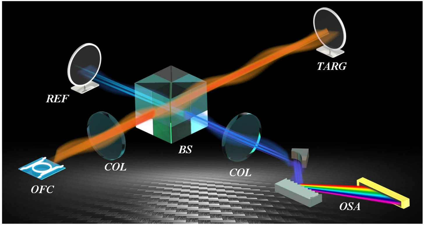
Figure 1.Schematic of DPI system used for distance measurement. COL, collimating mirror; BS, beam splitter; REF, reference mirror; OSA, optical spectrum analyzer; TARG, target mirror.
![]()
Figure 2.Comparison of dead zone of mode-locked OFC and SMC. The dead zone is introduced by the mismatch between the repetition rate of the OFC and the resolution of the optical spectrum acquisition system. Using an SMC with a repetition rate higher than
Actually, for a given optical spectrum acquisition system, a simple and effective solution of this issue is using a high repetition rate OFC to shorten the distance measurement cycle, i.e., . When the repetition rate of the OFC is higher than ( is the air group refractive index, is the resolution of the optical spectrum acquisition system), the dead zone will be totally eliminated, as shown in Fig. 2. The emergence of a novel type of integrated broadband coherent optical sources known as microresonator-based soliton microcombs (SMCs) makes this solution possible. Realizing double balances between nonlinearity and dispersion as well as parametric gain and cavity loss in a micrometer-scale optical resonator, an SMC can provide an equidistant comb-shaped spectrum like a traditional mode-locked OFC [29–35]. Benefiting from the miniature structure of the microresonators, SMCs are featured by an ultrahigh repetition rate. Since it emerged, the SMC has exhibited unprecedented prospects in the areas of classical and quantum optical communication systems [36,37], dual-comb spectroscopy [38], chip-scale optical frequency synthesizers [39], and high-accuracy ranging [40,41]. In our work, a self-developed SMC is employed to improve the performance of DPI-based long-distance ranging system.
Sign up for Photonics Research TOC. Get the latest issue of Photonics Research delivered right to you!Sign up now
Benefiting from the ultrahigh repetition rate, an SMC is an ideal laser source to eliminate the dead zone of DPI-based lidar and has a great advantage for compact integration. Besides, the ultrahigh repetition rate of an SMC reduces the demand on spectrometer resolution due to fewer optical modes among each interference spectrum, which is propitious for dynamic and high-speed measurement. To achieve dynamic nanometer measurement at long distances, we built an SMC-based DPI system, where a high-speed InGaAs linear array image sensor (LAIS) is employed for interference spectrum collection that enhances the data acquisition rate, and the periodic ambiguity is extended to 1500 m via an auxiliary dual-frequency phase-modulated laser range finder (PLR). The feasibility of the proposed measurement system is experimentally demonstrated in two scenarios. In the first scenario, an 80 m distance is measured in a well-maintained environment where a high-accuracy incremental laser interferometer group (IMG) is used as reference. For the second scenario, the ranging system is built in an outdoor baseline for up to a 1179 m distance measurement. The results show that the proposed SMC lidar system has the potential to realize nanometric-precision measurement of long distance with a high real-time updating rate of up to 35 kHz. Also, the proposed SMC lidar could be extended from millimeter to hundreds of kilometers length measurement, as well as holding the potential for miniature integration aimed at the various applications of long-distance measurement such as formation flying of satellites, advanced manufacturing, and the frontiers of scientific research.
2. METHODS
A. Soliton Microcomb Generation
The core SMC is generated in a high-index doped silica glass microring resonator (MRR) with a quality factor of 1.7 million [42,43]. Two key techniques are adopted to ensure the SMC generates and survives in the unguaranteed experimental environment. First, the MRR is butterfly-packaged with a compact thermal electric cooler (TEC) [Fig. 3(b)].
![]()
Figure 3.Single SMC generation in a high-index doped silica glass MRR. (a) Experimental setup for SMC generation. An auxiliary laser-assisted intracavity thermal-balanced scheme is adopted for single SMC generation. (b) Image of the butterfly-packaged MRR; (c) typical optical spectrum of the single SMC. Left inset, enlarged comb lines; right inset, electrical spectrum of single SMC. ECDL, external cavity diode laser; EDFA, erbium-doped optical fiber amplifier; FPC, fiber polarization controller; Cir, circulator; PD, photodetector; ESA, electrical spectrum analyzer; OSA, optical spectrum analyzer.
The TEC is used to tune the resonances of the MRR for SMC generation and isolate the temperature fluctuation of the external environment to maintain the SMC. Second, an auxiliary laser-assisted intracavity thermal-balanced scheme is adopted to access single SMCs in a deterministic fashion [42]. The experimental setup is shown in Fig. 3(a). In our experiments, the wavelength of a pump laser is fixed at 1560.2 nm with a linewidth of 100 Hz. The pump and auxiliary lasers have similar on-chip power of . Figure 3(c) shows a typical optical spectrum of a single SMC, which exhibits a standard squared hyperbolic secant () envelope. The mode-crossing is almost avoided over the SMC bandwidth, which benefits from the stringent spatial mode control of the device. The repetition rate of the single SMC is 48.97 GHz, corresponding to a pulse spacing of 20.4 ps. As an ideal broadband coherent laser source, the single SMC can survive over 2 h in the outdoor environment, which is critical for our long-distance measurement experiments.
B. Principle of the SMC Lidar
Figure 4 shows the principle of the proposed SMC lidar where two channels, the DPI channel and the PLR channel, are included. For the DPI channel, the self-developed SMC is split into signal and reference combs using an 80∶20 optical coupler (OC), and an optical attenuator (OA) is used to compensate for the transmission loss of the signal comb to improve the visibility of interference fringes. The interference spectrum of the reflected signal comb and the reference comb is spatially separated using two concave mirrors (CMs) and a reflection grating before lighting to a 256-pixel InGaAs LAIS for interference fringe detection [Fig. 4(a)]. The detection system is well designed to ensure that each LAIS pixel is illuminated by a single SMC mode (about 250 valid optical modes). The exposure time of the LAIS can be flexibly set between 26 and 260 μs by adjusting the integration time, which corresponds to a maximum measurement frequency of , with an additional start-up time of 2.5 μs. An equivalent average process is realized during the spectrum acquisition, which is helpful in alleviating the impact of white noise coupled from the pump source, the erbium-doped optical fiber amplifier (EDFA), and the external environment.
![]()
Figure 4.Principle of the proposed SMC lidar. A dual-frequency PLR is employed for rough distance evaluation. (a) SMC generator. A single SMC is split to signal and reference combs using a 20∶80 OC. (b) Interference spectrum acquisition system. Two CMs and a reflection grating are designed to separate the interference spectrum spatially, which ensures each pixel of the LAIS is exposed by a single SMC mode. (c) Schematic of the PLR for distance evaluation. A phase-modulated LD is used as optical source, and the phase variation is demodulated by a phase detector. (d) An IMG, including three He–Ne laser interferometers to eliminate Abbe error, is used to provide a high-precision absolute distance reference. (e) Typical interference spectrum of the SMC-based DPI ranging system; (f) FFT spectrum of the interference spectrum envelope; (g) zoom-in vision of the FFT spectrum. A three-point fitting method (red line) is employed to extract the exact delay time. CM, concave mirror; LAIS, linear array image sensor; OC, optical coupler; OA, optical attenuator; CW, continuous wave laser; EDFA, erbium-doped optical fiber amplifier; CIR, circulator; LD, laser diode; APD, avalanche photodiode; COL, collimating mirror; WDM, wavelength division multiplexer.
Assuming the spectrum of the SMC is expressed as , where is the angular frequency of every optical mode of the SMC, the signal and reference combs are expressed as
For the PLR channel, a dual-frequency PLR is employed to estimate the distance and to compensate for the ambiguity of the distance measurement cycle, which is parallel to the SMC-based DPI using a wavelength division multiplexer (WDM) technique, as shown in Fig. 4(c). A phase-modulated laser diode (LD) is used as a light source, and the phase difference between the original modulation signal and the reflected laser signal is regained using a fast Fourier transform (FFT) digital phase discrimination technique. By switching the LD modulation frequencies, two signals are generated by a direct digital synthesis signal generator with 100 kHz frequency difference, i.e., and . A heterodyne method is used to convert the high-frequency phase signals to a low-frequency signal (100 kHz), which facilitates the distance information demodulation. The measurement laser signal is detected by an InGaAs avalanche photodiode (APD) detector. The phase shift of the laser signal is demodulated by a full-phase digital FFT phase discriminator whose precision is about 0.1° for 100 kHz signals. In our scheme, the absolute distance under test can be real-time synthesized once the distance information from DPI and PLR channels is obtained simultaneously.
![]()
Figure 5.Ultimate distance result synthesis procedure. (a) Schematic diagram of ultimate distance synthesis.
3. RESULTS
To verify the capacity of our SMC lidar, we demonstrate the experimental implementation of an 80 m range in a well-maintained environment and a 1179 m range in an outdoor environment, respectively.
A. Ranging in a Well-Maintained Environment
The proposed SMC lidar is first implemented in a well-maintained environment. The target is mounted on an 80 m-long precision granite guide rail system that is installed in a 10 m deep basement at the National Institute of Metrology (NIM), China. The environmental parameters, including temperature, humidity, acoustical vibration, and atmosphere pressure, are well monitored and controlled using the mounted sensor arrays and control systems, which results in minor environmental turbulence. The air refractive index is calibrated in real time using the monitored environmental data based on the modified Edllen’s formula.
To obtain absolute precision, a referenced absolute distance is simultaneously measured using an IMG. The IMG consists of three parallel installed He–Ne interferometers for Abbe error elimination [Fig. 4(d)]. The absolute precision of the IMG is in the controlled environment. A reference point (zero distance) is calibrated by the proposed scheme and the IMG ranging system synchronously. Then, the target mirror is moved from 0 to 3 mm with a step size of 50 μm. The measured results are shown in Fig. 6(a) (top), while the residuals between the measured and reference values are presented in Fig. 6(a) (bottom) with standard deviation error bars. The residuals are within 100 nm, which indicates the two ranging systems have a similar accuracy. The accuracy of the IMG ranging system linearly decreases as the distance increases. It is no longer suitable as a reference for long-distance ranging. Therefore, a standard deviation analysis is used for measurement accuracy assessment in our following experiments. For longer distance measuring experiments, the target is placed around 1 and 80 m, respectively, and the interference spectra are continuously acquired for 6 s with an updating rate of 35 kHz. Based on a fast peak fitting algorithm and a timely distance demodulation technique [45], the distance information can be recovered in a timely fashion in a medium-performance field-programmable gate array.
![]()
Figure 6.Experimental results of distance ranging in a well-maintained environment. (a) Measurement results when the target moves from 0 to 3 mm with a step size of 50 μm. Top, measured results versus set distance; bottom, residuals between the DPI and IMG ranging results; the standard deviations are labeled with error bars (magenta). (b) Fractional parts of the measurement results of 1 m ranging experiment; (c) fractional parts of the measurement results of 80 m ranging experiment; (d) Allan deviations versus average time of 1 and 80 m ranging experiments.
The fractional parts of the measurement results of the 1 and 80 m ranging experiments are shown in Figs. 6(b) and 6(c), and the standard deviations are 2.99 and 9.95 nm; the repeatability precision is 28 and 59 nm, respectively. The minimum Allan deviations of the two ranging experiments are 2.88 nm at an average time of 2.74 s, and 5.39 nm at an average time of 2.055 s, respectively [Fig. 6(d)]. It is noted that there are apparent distance drifts for 80 m distance measurements [Fig. 6(c)], which is caused mainly by environmental fluctuation. We believe that the ranging error could be further improved once the environmental fluctuation is well compensated.
B. Long Distance Ranging in an Outdoor Environment
The environmental applicability of the proposed SMC lidar is validated by building the system in a 1200 m outdoor standard baseline located at NIM [Fig. 7(b)]. Environmental parameters along the baseline, including temperature, air pressure, and humidity, are also monitored to calculate the air group refractive index. Temperature is monitored by 60 high-precision Pt-100 platinum resistance temperature sensors, which are installed along the baseline with a spacing of 20 m. Air pressure and humidity are monitored by 3 air pressure sensors and 13 humidity sensors along the baseline. To overcome the optical energy loss caused by beam expansion, an optical transmitter-receiver system is constructed, which consists of a Cassegrain telescope and an automatic space-to-fiber coupling system [Fig. 7(a)]. An eyepiece is used to collimate the light path and aim at the target. The automatic space-to-fiber system optimizes the coupling efficiency through a piezoelectric scanning method. The transmitting–receiving efficiency is about 1%, which is enough for our ranging experiments.
![]()
Figure 7.Experimental setup of long-distance ranging in an outdoor environment. (a) Layout of the long-distance ranging experiments. The emitted light is coaxial to the reflected light with the help of two reflectors. The lower left is a photograph of the experimental setup. A cube-corner prism is used as the target mirror and installed on a piezoelectric vibrator (lower right). (b) Satellite image of the outdoor baseline of NIM. The distance to be measured is
A cube-corner prism is used as the target and placed at about 1179 m away from the optical transmitter–receiver. In order to test the resolving ability of the proposed ranging system, the cube-corner prism is installed on a piezoelectric vibrator to provide high-frequency vibration signals, as shown in Fig. 7(a). According to the test result of the PLR channel, is determined to be 385,072. Considering the air effect group refractive index, which is calculated to be 1.000,267,232 using the modified Edllen’s formula based on the area weighted averaging parameters along the baseline, the integer part of the stationary distance of the target is calibrated to 1,179,305.255,157,9 mm.
The fractional part of the stationary distance is continuously recorded using the proposed ranging system for 5 s, as shown in Fig. 8(a), where three conditions are included, that is stationary, 1 kHz vibration, and 5 kHz vibration. It can be seen that there is an obvious distance drift of , which is mainly induced by the low-frequency noise, arising from the temperature drift, environmental acoustic interference, as well as air turbulence. The low-frequency noise can be clearly observed in the FTS [Fig. 8(d)] which is inevitable in an outdoor environment. According to the modified Edllen’s formula, temperature is the main factor in the change of the air refractive index (e.g., a 1°C temperature fluctuation will result in an air refractive index changing by , corresponding to optical length drift for the distance of 1179 m).
![]()
Figure 8.Experimental results of long-distance ranging in an outdoor environment. (a) Ranging results under three conditions: stationary (blue), 1 kHz vibration (red), and 5 kHz vibration (yellow); (b) zoom-in of the ranging results; (c) Allan deviations of the stationary ranging results versus averaging time before and after an HP filter; (d) frequency spectra of three conditions.
To alleviate the effect of low-frequency noise induced by environmental disturbances and temperature shifts, a digital high-pass (HP) filter is employed. Figure 8(c) shows the Allan deviation of the stationary results before and after the HP filtering. Without the HP filter, the minimum Allan deviation is 5.6 μm at an average time of 0.2 ms, and the Allan deviation increases, along with the average time increasing, up to 57 μm. Using an HP filter, the Allan deviation continuously decreases with an increased average time, and a minimum deviation of 27 nm is obtained at an average time of 1.8 s. 27 nm is regarded as the ranging capability of our outdoor ranging system, which is limited by the air dispersion, which broadens the soliton pulse and leads to the spectral chirp (different arrival times of different optical modes).
Such a system would show better performance in a nondispersive environment such as outer space, where the air refractive index fluctuation and air dispersion are eliminated. Further, the capacity of high-frequency vibrations measurement is verified by imposing a modulation signal on the piezoelectric vibrator, e.g., two frequencies of 1 and 5 kHz. The corresponding real-time ranging results are shown by the red and yellow lines in Fig. 8(a), respectively. The zoom-in waveforms [Fig. 8(b)] represent vibrations of the target; the vibrational frequencies are clearly indicated by the Fourier transform spectra [Fig. 8(d)].
C. Precision Analysis
The continuous precision analysis of length measurement is illustrated in Fig. 9, where the absolute precision and relative precision are depicted in blue and brown lines, respectively. The measuring range is divided into four areas, i.e., the micronano area, the general area, the long-length and the ultralong areas. In the first two areas, the main factors affecting the precision are the systematic error of measuring systems, such as the frequency stability of the laser source, the dispersion error, and the algorithm error. Ideally, absolute precision can be kept better than tens of nanometers. For long-length and ultralong areas, the fluctuation caused by the air refractive index gradually becomes the dominant factor influencing precision. Consequently, the relative precision can only approach the level of air variation, i.e., . If the air refractive index can be compensated, precision can be further improved.
![]()
Figure 9.Precision analysis of length measurement. The blue and brown lines are the absolute precision and the relative precision as a function of the length on measure, respectively. The yellow line is the absolute precision of measuring result after HP filtering as a function of the length on measure with the minimum Allan deviation of 27 nm marked with a red point.
On the other hand, absolute accuracy is not necessary in many ranging applications, but the dynamic process or special frequency may be more crucial, and this information could be obtained by just removing the low-frequency fluctuation of air with an HP filter. As the yellow line in Fig. 9 shows, precision is heavily improved after filtering the low-frequency fluctuation, and the trend inhabits the general area. The minimum Allan deviation of 27 nm can effectively represent the length-measuring capability of the built system. Especially for applications in outer space, such as multisatellite flying formations, where the measurement path is close to a vacuum, it is able to achieve dynamic precise measurement of kilometers’ distance with tens of nanometers of absolute precision. For applications in an outdoor air environment as in the demonstrated experiments, employing a dual-band OFC source is one of the possible solutions to compensate for the air refractive index, which still needs to be further researched.
4. DISCUSSION AND CONCLUSION
In this research, aimed at achieving high-speed long-distance ranging with high precision, a chip-scale SMC is introduced to a DPI system for the first time. Traditionally, high-precision long-distance ranging requires complex steps and calculations, which are difficult to apply in practice and which sacrifice real-time performance. Here, both the theoretical analysis and the experimental results show that the problems of existing measuring schemes comprising a large dead zone, low precision, and poor real-time performance can be completely avoided. The proposed SMC lidar is experimentally demonstrated in both a well-maintained environment and an outdoor standard baseline, where the distance detection accuracy reaches nanometer scale. Even for outdoor long-distance measurement of more than 1179 m, a minimum Allan deviation of 27 nm is achieved when the effect of the air refractive index fluctuation is neglected.
Moreover, for the proposed scheme, the maximum measurable distance is determined by the available laser power as well as the coherent length of the laser source. The SMC is pumped by a 100 Hz linewidth laser, which ensures the coherent length of the SMC over 1000 km [46]. Therefore, such a ranging system has the potential to extend the measurable distance to hundreds of kilometers as long as a long-distance light transmitting–receiving antenna is available. Additionally, the measuring speed of our scheme is subject to the spectrum acquisition rate. Actually, each soliton pulse can act as an effective distance probe; thus the maximum achievable measuring speed can approach the repetition rate of SMC (i.e., 48.97 GHz) once an ultrahigh-speed photodetector array is available. The proposed SMC lidar is therefore a promising technique applicable to ultrafast optical three-dimensional shape measurement. In conclusion, the excellent features, large dynamic range, ultrahigh precision, extreme measuring speed, and the compact system-on-a-chip integration potential ensure the SMC lidar can have extensive application prospects in both scientific and industrial areas.
Acknowledgment
Acknowledgment. F. Z., W. W., W. Z., Wei. Z., and X. Q. organized the project. J. W., Z. Lu., J. C., and Y. W. conducted the various experiments. J. C., J. W., and J. Z. analyzed the data. W. Z., W. W., S. C., and B. L. designed and fabricated the devices. W. W. packaged the samples. All authors discussed results and commented on the paper. J. W., Z. L., W. W., and W. Z. wrote the paper. W. Z. and F. Z. supervised the project. We thank the experimental sites supported by the National Institute of Metrology (NIM), China.
References
[2] N. White. X-ray astronomy—imaging black holes. Nature, 407, 146-147(2000).
[9] T. Udem, R. Holzwarth, T. W. Hansch. Optical frequency metrology. Nature, 416, 233-237(2002).
[24] Z. Zhu, G. Wu. Dual-comb ranging. Engineering, 4, 772-778(2018).
[41] M. G. Suh, K. J. Vahala. Soliton microcomb range measurement. Science, 359, 884-887(2018).

Set citation alerts for the article
Please enter your email address
© Copyright 2018-2021 | Chinese Laser Press. All Rights Reserved 沪ICP备15018463号-20