
Hiromitsu Kiriyama, Yasuhiro Miyasaka, Akira Kon, Mamiko Nishiuchi, Akito Sagisaka, Hajime Sasao, Alexander S. Pirozhkov, Yuji Fukuda, Koichi Ogura, Kotaro Kondo, Nicholas P. Dover, Masaki Kando. Enhancement of pre-pulse and picosecond pedestal contrast of the petawatt J-KAREN-P laser[J]. High Power Laser Science and Engineering, 2021, 9(4): 04000e62
- High Power Laser Science and Engineering
- Vol. 9, Issue 4, 04000e62 (2021)
Abstract
1. Introduction
With the remarkable progress in chirped-pulse amplification (CPA) technology and Ti:sapphire laser media, femtosecond lasers with very high peak powers of 1–10 petawatt (PW)[1–6] have been developed around the world and extremely high intensities of 1022–1023 W/cm2[7–9] are now available. Owing to the limitation of the available size and transverse parasitic oscillation in the Ti:sapphire gain media, femtosecond lasers based on optical parametric chirped-pulse amplifiers (OPCPAs) with a peak power of order 100 PW have been designed and are under construction[10,11]. The laser intensity will possibly exceed 1023 W/cm2 in the near future. With the development of ultra-high-intensity femtosecond lasers, the investigations of electron acceleration, ion acceleration, X-/γ-ray generation and astrophysical systems are being actively pursued.
For laser–matter interaction experiments at such an intense level, the temporal contrast of the laser pulse is a key parameter. Temporal contrast, defined as the ratio of the intensity of the peak of the main pulse to that of pre-pulses or background in different temporal ranges, is required to be as high as possible to minimize unwanted pre-plasma dynamics. Any pre-pulses and background with the intensities of 1010–1011 W/cm2 are capable of ionizing solid targets, which will then greatly influence the laser–matter interaction process. Therefore, the temporal contrast is crucial for accessing high-field physics and is now under intense investigation throughout the world. It is necessary to develop pulse cleaning techniques in an ultra-high peak power laser to satisfy the experimental requirements. The poor contrast can take the form of amplified spontaneous emission (ASE) extending over nanoseconds[12], and discrete pre-pulses that are usually within a few hundred picoseconds of the main pulse[13]. A third contribution is uncompressible energy within the stretched pulse, which manifests itself as an exponentially rising pedestal, typically within tens of picoseconds of the main pulse[14,15].
Several methods have been investigated, based on temporal cleaning or filtering techniques, for example, relying on double CPA (DPCA)[16], ultrafast electro-optic switches[17], saturable absorbers[5], cross-polarized wave generation in nonlinear crystals[18], hybrid amplification in femtosecond lasers based on OPCPA at the front-end section[19], second harmonic generation (SHG)[20] and plasma mirrors (PMs)[21]. The SHG and PM schemes are used as the final temporal cleaner at the full compressed pulse in the CPA laser chain[22,23]. ASE contrast of greater that 1010 has been achieved by using these techniques at PW class peak powers. With the recent significant enhancement of the ASE contrast, pre-pulses and pedestals that were previously buried in the ASE have risen to prominence.
Sign up for High Power Laser Science and Engineering TOC. Get the latest issue of High Power Laser Science and Engineering delivered right to you!Sign up now
Removing post-pulses is also essential in order to minimize the pre-pulse. Even though the post-pulses do not directly influence laser–matter interaction experiments, nonlinear effects of post-pulses in the laser can lead to the formation of pre-pulses. If the time between the main pulse and post-pulse is less than the duration of the stretched pulse in a CPA system, the pulses overlap in time and interfere with each other, resulting in spectral interference equivalent to spectral modulation within the main pulse. As this pulse is amplified and transmitted through optical elements, such as windows and amplifier crystals, the phase is also modulated due to nonlinear optical effects. Upon recompression of the pulse, both pre-pulses and post-pulses are therefore generated. The magnitude of the pre-pulses is determined by both the B-integral and the intensity of the original post-pulse[13,24–28]. The unwanted pre-pulses can strongly affect targets placed at the high-power laser focus, causing ionization and target pre-heating. Therefore, it is important to investigate the pre-pulse generation mechanism and remove strong post-pulses to minimize target disruption in high-intensity laser plasma experiments.
There is also a common temporal feature in all high-intensity laser systems that is responsible for the degradation of the temporal contrast in the tens of picoseconds range. In CPA lasers, a laser beam is spectrally resolved on optics in a stretcher and compressor. Thus, the surface roughness causes a relative phase shift at each wavelength and is directly converted to random spectral phase noise (RSPN). This means that the surface quality of the stretcher and compressor optics, such as the mirror and gratings, is important for spectral phase noise, which reduces the temporal contrast of the main pulse and generates a noisy structure on both sides of the main pulse[14,15,29]. Recently, Ranc et al. have shown that the RSPN from the primary convex mirror in Öffner stretchers is the principal source of this feature. This feature is termed the coherent contrast pedestal and is of concern because its effect is to extend the rising edges of the pulse by tens of picoseconds to several picoseconds at an intensity that is likely to be well above the plasma generation threshold. Therefore, this pedestal should be managed carefully and improved by orders of magnitude of tens of picoseconds before the main pulse.
In this paper, we report on a detailed study of pre-pulses generated by the post-pulses and the pedestal contrast in J-KAREN-P, a PW Ti:sapphire laser at the National Institutes for Quantum and Radiological Science and Technology (QST) in Japan. Our experimental investigation of this study is organized in two steps. Firstly, we describe the experimental observation and investigation for deeper understanding of the behavior of the pre-pulses generated by post-pulses. We discuss three surprising observed features of the generated pre-pulses. Firstly, in the case where there is a long time delay between the main pulse and post-pulse, the generated pre-pulse delay does not correspond to that of the post-pulse. Instead, the pre-pulses are slightly delayed in time. Secondly, in such conditions the pulse shape of the pre-pulse is unsymmetrically distorted. Finally, the peak intensities of the pre-pulse are strongly suppressed compared to predictions. Furthermore, we will briefly describe the identification of the origins of the pre-pulses generated by post-pulses and removal of the pre-pulses in the J-KAREN-P experimentally. We then demonstrate orders of magnitude enhancement of the pedestal contrast of the J-KAREN-P pulse by improving the surface quality of the convex mirror in the Öffner stretcher.
2. Description of J-KAREN-P
J-KAREN-P[5,30] is a PW CPA laser system based on Ti:sapphire. A schematic block diagram of the J-KAREN-P system is shown in Figure 1. The system includes a DCPA architecture to improve the contrast. The first CPA stage provides a 25 fs, sub-millijoule pulse, which is transmitted through a saturable absorber. The pulse is then re-stretched using a grating-based all-reflective Öffner stretcher for the second CPA stage. An acousto-optic programmable dispersive filter (AOPDF) is implemented to compensate for high-order dispersion terms resulting from beam propagation, and a small-aperture Faraday isolator is used to prevent back-reflected pulses. The pulses then enter a three-stage OPCPA pre-amplifier, which provides amplification with both broad bandwidth and high contrast. The OPCPA is pumped by a frequency-doubled Nd:YAG laser (Amplitude Laser Group Continuum, Intrepid), which can deliver an arbitrary temporal pulse shape using a programmable optical pulse shaper consisting of a Mach–Zehnder modulator, a bias control circuit and a programmable arbitrary pulse synthesizer. The pulses subsequently pass through an ultrafast Pockels cell, improving the nanosecond-order ASE, before being further amplified in a Ti:sapphire pre-amplifier, a cryogenically cooled Ti:sapphire power amplifier and two booster amplifiers. A large-aperture Faraday isolator is also placed between the Ti:sapphire pre-amplifier and the power amplifier to prevent any backward propagating pulses. The fully amplified pulses are then recompressed in a grating-based compressor. The spectral phase is measured using a high-dynamic single-shot diagnostic system (Fastlite, Wizzler) after the compressor, and then fed back to the AOPDF to minimize phase distortion. The durations of the stretched and recompressed pulses in this experiment were approximately 0.5 ns and approximately 40 fs, respectively.
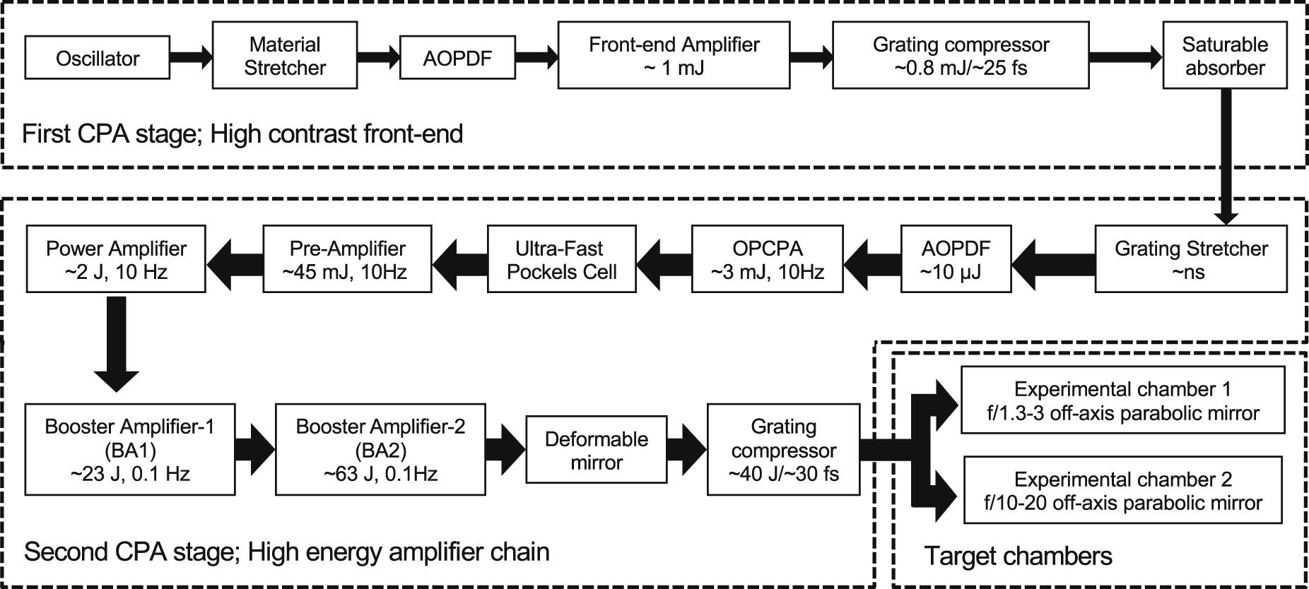
Figure 1.Schematic block diagram of the J-KAREN-P laser system.
3. Experimental study of pre-pulses generated by post-pulses
3.1. Pre-pulses generated by post-pulses
To facilitate the generation of controlled post-pulses, five uncoated fused-silica plane-parallel plates of different thicknesses were prepared for installation into the beamline. The thicknesses of the plates were approximately 1, 3, 5, 8 and 11.8 mm, and they were installed perpendicularly to the laser propagation direction directly before the Ti:sapphire pre-amplifier. The plates give a reflectivity of typically approximately 3.4% per surface, and result in a post-pulse via a double reflection of the incident pulse off two surfaces at a contrast level of approximately 10–3. The thicknesses were chosen to allow a range of delays between the main pulse and post-pulse. For the thinnest plates, most of the pulses are overlapped, whilst for the thickest plates there is only partial overlap. The time delays were approximately t = 10, 30, 50, 80, 118 ps, determined by t = 2dn/c, where d is the thickness of the plates, n = 1.45 is the refractive index of the plane-parallel plates and c is the speed of light. The laser pre-pulses and post-pulses were measured with a third-order cross-correlator (Amplitude Technology, Sequoia, Paris, France). For calibration, we also inserted the plates directly in front of the third-order cross-correlator in the calibration. As this is after amplification and recompression, there is no pre-pulse generation when the plates are placed at this position. The measured post-pulse intensity agrees with the prediction of the Fresnel equations. We also observed the pre-pulse generated artificially in the third-order cross-correlator, due to the mixing of the post-pulse second harmonic and the fundamental of the main peak. The artificial pre-pulse intensity is the square of the post-pulse contrast, approximately 10–6.
The pre-pulse generation using different thickness plane-parallel plates is shown in Figure 2. The measurements were taken at three different amplification levels: (1) approximately 45 mJ of the Ti:sapphire pre-amplifier output; (2) approximately 1.8 J of the Ti:sapphire power amplifier output; and (3) approximately 26 J of the booster amplifier output. The different amplification levels result in different values of accumulated B-integral in the laser system. For all amplification levels, the pulses were attenuated appropriately using wedged plates to provide the same level of laser energy at the third-order cross-correlator.
![]()
Figure 2.Measured pre-pulse contrast in the J-KAREN-P laser system with the plane-parallel plates of (a) approximately 1 mm, (b) approximately 3 mm, (c) approximately 5 mm, (d) approximately 8 mm and (e) approximately 11.8 mm. The green line is for calibration (the plane-parallel plate is placed after the compressor). The blue line, red line and black filled circles are obtained with the output energies of approximately 45, 1.8 and 26 J, respectively. These energies correspond to the B-integrals of approximately 0.037, 0.25 and 0.85 rad, respectively.
For a plate thickness of approximately 1 mm, the post-pulse was generated at approximately 10 ps after the main pulse with an approximately 10–3 contrast, resulting in an artificial pre-pulse at approximately 10 ps of an approximately 10–6 contrast before the main pulse, as seen from the green curve in Figure 2(a). Increasing the pulse energy resulted in increasing pre-pulse contrasts of approximately 4.1 × 10⁻⁶ (blue line), 5.3 × 10⁻⁵ (red line) and 6.8 × 10⁻⁴ (black filled circles) in Figure 2(a), with corresponding calculated B-integral values of approximately 0.037, 0.25 and 0.85 rad, respectively. The B-integral was estimated by considering all the transmissive optics in the laser chain. The calculated B-integral value is not linearly related to the laser pulse intensity because of the different beam diameters for each amplifier. At the maximum amplification level, giving pulses of approximately 26 J, the pre-pulse was approximately 1000 times stronger than the artificial pulse generated in the third-order cross-correlator. The increase of pre-pulse magnitude with the B-integral is due to the accumulation of the nonlinear effects[13] and can be theoretically estimated to be 4.6 × 10⁻⁷, 2.0 × 10⁻⁵ and 2.4 × 10⁻⁴ for the three different B-integral values, respectively. Note that for small values of the B-integral, the real pre-pulses are hidden by the stronger artificially generated pre-pulse. The experimental data agree with the theoretical predictions relatively well.
When using thicker plane-parallel plates, as shown in Figure 2, three interesting features were found. Unlike the observations from thinner plates, the timing of the pre-pulse peak differs somewhat with the corresponding post-pulse timing, even though the artificial pulse remains at the same delay as the post-pulse. The temporal pre-pulse shape is also found to be asymmetric, characterized by a faster rise time and slower fall time. Finally, the pre-pulse peak intensity is smaller than the theoretical predictions[13]. This is exemplified by the behavior using the thickest plate, shown in Figure 2(e). Despite the post-pulse coming 118 ps after the main pulse, and the corresponding artificial pre-pulse generated by the third-order cross-correlator generated at 118 ps before the pulse, the real pulse was generated at 113.2 ps before the main pulse, a shift of 4.8 ps. The real pre-pulse shows significant asymmetry between the rising and falling edge. The absolute height of the pre-pulse peak was also suppressed compared to thinner plates. The different modes of laser amplification with the 11.8 mm plate resulted in pre-pulses of approximately 1.8 × 10⁻⁸ (blue line), 2.0 × 10⁻⁶ (red line) and 3.8 × 10⁻⁶ (black filled circles), corresponding to B-integral values of approximately 0.037, 0.25 and 0.85 rad, respectively. At maximum amplification, the pre-pulse intensity reached approximately 6.8 × 10⁻⁴ with a 1 mm thick plate, but only approximately 3.8 × 10⁻⁶ with an 11.8 mm plate, a reduction of more than two orders of magnitude. The relationship of pre-pulse intensity and delay with parallel-plate thickness is given in Figure 3.
![]()
Figure 3.(a) Summary of pre-pulse peak contrast in the J-KAREN-P laser system with plane-parallel plates of approximately 1, 3, 5, 8 and 11.8 mm. The blue, red and black filled circles are obtained with the output energies of approximately 45, 1.8 and 26 J, respectively. These energies correspond to B-integrals of approximately 0.037, 0.25 and 0.85 rad, respectively. (b) Summary of the time delay versus the plane-parallel plate thickness.
Although our measurements for thinner plane-parallel plates were in reasonable agreement with theoretical predictions[13], the surprising pre-pulse properties resulting from the thicker plates are still not well understood at present and require further consideration. Increasing the plate thickness reduces the overlap between the stretched main pulse and post-pulse. Due to the chirped nature of the stretched beams, this means the spectral bandwidth over which the spectral intensity and phase are modulated becomes narrower. This naturally leads to a reduction in available energy to create the pre-pulse, which would naturally reduce the pre-pulse intensity. This is compounded by a longer pulse duration due to the narrow spectral bandwidth, further reducing the pre-pulse intensity. The pre-pulse clearly possesses a post-pulse foot following the peak with a decaying oscillatory modulation characteristic of positive higher odd-order dispersion, likely combined with self-phase modulation. As the window of spectral intensity modulation leading to the pre-pulse is different from that of the main pulse, the pre-pulse experiences more spectral phase modulation, which can cause it to be delayed in time. A full quantitative understanding of these effects is under investigation and will be presented in a future publication.
Following from these investigations with inserted plane-parallel plates, we have confirmed that the pre-pulse generated by the Ti:sapphire pre-amplifier crystal was also distorted and time-delayed, as shown in Figure 4. The post-pulse and artificial pulse were at a delay of approximately 186 ps before and after the main pulse, respectively, but an additional real pre-pulse was observed approximately 11 ps after the artificial pre-pulse. This pre-pulse was asymmetrically distorted and broadened, just as described above. We imply from this observation that the time delay increases quadratically with the optical path length, which is the product of the thickness and refractive index of the optical components in the system.
![]()
Figure 4.Representative measured artificial and real pre-pulses in the J-KAREN-P laser system by the Ti:sapphire pre-amplifier crystal.
3.2. Pre-pulse contrast improvement
Figure 5(a) shows the measured contrast of the J-KAREN-P laser system. According to our above experience and knowledge, we have identified pre-pulses and artificial pulses generated by the post-pulses. The pre-pulses at approximately 270, 175, 137, 96 and 40 ps are real, coming from the post-pulses due to double reflection in the Ti:sapphire crystal of the power amplifier, the Ti:sapphire crystal of the pre-amplifier, the small-aperture Faraday isolator between the stretcher and the OPCPA, the windows of the cryogenically cooled power amplifier and the optics inside the oscillator, respectively. These real pre-pulses in Figure 5(a) imply the existence of artificial pulses. The two pre-pulses at approximately 298 and 186 ps before the main pulse are artificial pulses originating from the Ti:sapphire crystals of the power amplifier and pre-amplifier, respectively. These two artificial pulses can be seen more clearly because of the long time delay between the artificial and real pre-pulses, while the other artificial pulses appear to overlap with the real pre-pulses because of the shorter time delay between the artificial and real pre-pulses.
![]()
Figure 5.Typical contrast of the J-KAREN-P laser system (a) before and (b) after employing optical components with a small wedge angle.
After identifying the source of all the pre-pulses, we endeavored to remove them by avoiding post-pulse generation in our laser system. This was implemented by adding a small wedge to the post-pulse generating Ti:sapphire crystals and windows. The wedge is orientated horizontally to enable angular dispersion compensation in the four-pass amplifier geometry. The angular dispersion of the output pulse was also calculated with Zemax software, and it was found to be negligible and result in no focal spot degradation, which was subsequently experimentally confirmed. We also removed the small-aperture Faraday isolator, eliminating its pre-pulse, as it was found to be unnecessary with the current system configuration. The final remaining pre-pulse at 40 ps before the main pulse is generated in the oscillator and is difficult to remove. A PM system will therefore be introduced to suppress its impact on high-power laser plasma experiments. The subsequent contrast with wedged optical components is displayed in Figure 5(b), showing the elimination of all pre-pulses except the one originating from the oscillator.
4. Experimental study of the coherent contrast
In our previous theoretical investigation, we reported a detailed analysis of the influence of RSPN on the temporal contrast of an ultra-high-intensity laser pulse[14]. We accurately evaluated the impact of stretcher and compressor optics on the contrast pedestal of the ultra-high-intensity laser pulse by precise quantitative characterization of the optics surface. The surface roughness of tens of nanometers on the stretcher and compressor optics causes RSPN, which reduces the temporal coherence of the main pulse and generates a noisy structure around the main pulse. Recently, the impact of RSPN on the pedestal contrast was explored experimentally[15]. The results show clearly that the temporal pedestal greatly depends on the optics roughness of the convex mirror in the Öffner stretchers. We demonstrate the crucial impact of the surface roughness of the convex mirror in the Öffner stretcher on the contrast of the J-KAREN-P PW laser facility.
In the second CPA stage in the J-KAREN-P, the pulses are temporally stretched to over nanosecond duration by passing through an aberration-free, all-reflective, Öffner-type stretcher[31]. This stretcher consists of a 1480-grooves/mm grating, a 2000-mm radius of curvature mirror (400-mm width, 80-mm height), a 1000-mm radius of curvature convex mirror (150-mm width, 10-mm height) and a roof mirror. We prepared and compared two convex mirrors. The measured RMS (root mean square) values for the roughness of the two mirrors are 1–2 and 0.2–0.3 nm, respectively. Figure 6 shows the typical contrast of the J-KAREN-P laser system with the Öffner stretcher convex mirror roughness of 1–2 nm RMS (blue line) and 0.2–0.3 nm RMS (red line). The pedestal contrast of less than around 10–6 of the main pulse is improved by using higher quality convex mirrors. The improvement of the pedestal contrast by one to two orders of magnitude between these two mirrors in the –7 to –33 ps range is clearly observed. The spectral phase modulation leads to a reduction of the temporal contrast of the pulse, and the induced pedestal is directly linked to the power spectral density of the spectral phase[32]. The intensity of the pedestal scales quadratically with the amplification of the spectral phase. Our result is reasonably in agreement with the theoretical prediction. The reduction of the pedestal by the improvement of the convex mirror quality has revealed two pre-pulses at –19 and –14 ps that are generated by the post-pulses through the nonlinear coupling described above. The pre-pulse at –14 ps originates from the double reflection of the half-wave plate. The origin of the pre-pulse at –19 ps is not clear at the moment, but probably comes from the oscillator section. Because the contrast trace of Figure 6(b) is taken without the large-aperture Faraday isolator and with smaller laser energy, the intensity of the pre-pulse at –40 ps may be below the detection limit due to the smaller nonlinear coupling associated with the 40 ps post-pulse at a smaller B-integral. Further investigation is required. The pedestal that is closer to the main pulse is caused by the lower frequency spectral phase modulation in the other optics[32] and by the nonlinear transfer of the characteristic post-pedestal to pedestal[13]. This pedestal, with the rising slope just before the main pulse, has a non-negligible effect on the plasma physics processes occurring on the target surface. Because it is also difficult to remove these pre-pulses and the pedestal, we plan to suppress them by installing a PM in the future[23].
![]()
Figure 6.Typical contrast of the J-KAREN-P laser system with the Öffner stretcher convex mirror roughness of (a) 1–2 nm RMS (blue line) and (b) 0.2–0.3 nm RMS (red line).
5. Conclusions
We have experimentally measured in detail the properties of pre-pulses generated by the nonlinear coupling associated with post-pulses at different values of the B-integral, using the PW facility J-KAREN-P. When there is a small time difference between the main and post-pulses, a pre-pulse is generated before the main pulse at the same time difference as the delay between the main and post-pulses. However, for longer time differences between the main and post-pulses, the generated pre-pulse is offset in time, asymmetrically distorted and lengthened in time. The improved understanding of the pre-pulses allowed identification of all sources of pre-pulses in the J-KAREN-P system, almost all of which were subsequently eliminated via the use of wedged optical components.
We also demonstrate the impact of the surface quality of the convex mirror in the Öffner stretcher. Installing a higher quality convex mirror in the J-KAREN-P stretcher has resulted in a one to two orders of magnitude reduction in the intensity of the coherent pedestal. This simple method may pave the way to improve the inherent contrast of PW class lasers by directly using pre-pulse mitigation techniques.
Since 10 PW lasers were demonstrated recently and even 100 PW class lasers are under construction, the achievable focused intensities on targets are rapidly increasing. Therefore, great care has to be exercised in the design of the laser chain and its components to avoid the generation of the pre-pulses and the pedestal, which radically modify the laser–matter interaction processes. We believe that the results of the investigation described here, therefore, are useful guidelines for the characterization and improvement of pre-pulse contrast and will be of great significance for ultra-high peak power and ultra-high-intensity CPA-based lasers.
References
[1] N. C. Danson, C. Haefner, J. Bromage, T. Butcher, F. C. J. Chanteloup, A. E. Chowdhury, A. Galvanauskas, A. L. Gizzi, J. Hein, I. D. Hillier, W. N. Hopps, Y. Kato, A. E. Khazanov, R. Kodama, G. Korn, R. Li, Y. Li, J. Limpert, J. Ma, H. C. Nam, D. Neely, D. Papadopoulos, R. R. Penman, L. Qian, J. J. Rocca, A. A. Shaykin, W. C. Siders, C. Spindloe, S. Szatmari, M. G. M. R. Trines, J. Zhu, P. Zhu, D. J. Zuegel. High Power Laser Sci. Eng, 7, e54(2019).
[2] H. J. Sung, W. H. Lee, Y. J. Yoo, W. J. Yoon, W. C. Lee, M. J. Yang, J. Y. Son, H. Y. Jang, K. S. Lee, H. C. Nam. Opt. Lett., 42, 2058(2017).
[3] K. Nakamura, H. Mao, J. A. Gonsalves, H. Vincenti, E. D. Mittelberger, J. Daniels, A. Magana, C. Toth, P. W. Leemans. IEEE J. Quantum Electron., 53, 1200121(2017).
[4] W. Li, Z. Gan, L. Yu, C. Wang, Y. Liu, Z. Guo, L. Xu, M. Xu, Y. Hang, Y. Xu, J. Wang, P. Huang, H. Cao, B. Yao, X. Zhang, L. Chen, Y. Tang, S. Li, X. Liu, S. Li, M. He, D. Yin, X. Liang, Y. Leng, R. R. Li, Z. Xu. Opt. Lett., 43, 5681(2018).
[5] H. Kiriyama, S. A. Pirozhkov, M. Nishiuchi, Y. Fukuda, K. Ogura, A. Sagisaka, Y. Miyasaka, M. Mori, H. Saksaki, P. N. Dover, K. Kondo, K. J. Koga, Z. H. T. TEsirkepov, M. Kando, K. Kondo. Opt. Lett., 43, 2595(2018).
[6] F. Lureau, G. Matras, O. Chalus, C. Derycke, T. Morbieu, C. Radier, O. Casagrande, S. Laux, S. Ricaud, G. Rey, A. Pellegrina, C. Richard, L. Boudjemaa, C. Simon-Boisson, A. Baleanu, R. Banici, A. Gradinariu, C. Caldararu, D. B. Boisdeffre, P. Ghenuche, A. Naziru, G. Kolliopoulos, L. Neagu, R. Dabu, I. Dancus, D. Ursescu. High Power Laser Sci. Eng., 8, e43(2020).
[7] S. A. Pirozhkov, Y. Fukuda, M. Nishiuchi, H. Kiriyama, A. Sagisaka, K. Ogura, M. Mori, M. Kishimoto, H. Sakaki, P. N. Dover, K. Kondo, N. Nakanii, K. Huang, M. Kanasaki, K. Kondo, M. Kando. Opt. Express, 25, 20486(2017).
[8] Z. Guo, L. Yu, J. Wang, C. Wang, Y. Liu, Z. Gan, W. li, Y. Leng, X. Liang, R. Li. Opt. Express, 26, 26776(2018).
[9] W. J. Yoon, G. Y. Kim, W. Il, J. H. S. Choi, J. H. Sung, W. H. Lee, K. S. Lee, H. C. Nam. Optica, 8, 630(2021).
[10] J. Bromage, S.-W. Bahk, A. I. Begishev, C. Dorrer, J. M. Guardalben, N. B. Hoffman, J. Oliver, G. R. Roides, M. E. Schiesser, J. M. Shoup, M. Spilatro, B. Webb, D. Weiner, D. J. Zuegel. High Power Laser Sci. Eng., 7, e4(2019).
[11] J. Hu, X. Wang, Y. Xu, L. Yu, F. Wu, Z. Zhang, X. Yang, P. Ji, P. Bai, X. Liang, Y. Leng, R. Li. Appl. Opt., 60, 3842(2021).
[12] V. V. Ivanov, A. Maksimchuk, G. Mourou. Appl. Opt., 42, 7231(2003).
[13] V. N. Didenko, V. A. Konyashchenko, P. A. Lutsenko, Y. S. Tenyakov. Opt. Express, 16, 3178(2008).
[14] H. Kiriyama, Y. Mashiba, Y. Miyasaka, R. M. Asakawa. Rev. Laser Eng., 46, 142(2018).
[15] L. Ranc, L. C. Blanc, N. Lebas, L. Martin, J.-P. Ji-Ping Zou, F. Mathieu, C. Radier, S. Ricaud, F. Druon, D. Papadopoulos. Opt. Lett., 45, 4599(2020).
[16] P. M. Kalashnikov, E. Risse, H. Schönnagel, W. Sandner. Opt. Lett., 30, 923(2005).
[17] M. Kaluza, J. Schreiber, K. I. M. Santala, D. G. Tsakiris, K. Eidmann, J. Meyer-ter-Vehn, J. K. Witte. Phys. Rev. Lett., 93, 045003(2004).
[18] A. Jullien, O. Albert, F. Burgy, G. Hamoniaux, J.-P. Rousseau, J.-P. Chambaret, F. Augé-Rochereau, G. Chériaux, J. Etchepare, N. Minkovski, M. S. Saltiel. Opt. Lett., 30, 920(2005).
[19] H. Kiriyama, M. Mori, Y. Nakai, Y. Yamamoto, M. Tanoue, A. Akutsu, T. Shimomura, S. Kondo, S. Kanazawa, H. Daido, T. Kimura, N. Miyanaga. Opt. Lett., 32, 2315(2007).
[20] Y. Huang, C. Zhang, Y. Xu, D. Li, Y. Leng, R. Li, Z. Xu. Opt. Lett., 36, 781(2011).
[21] A. Lévy, T. Ceccotti, P. D’Oliveira, F. Réau, M. Perdrix, F. Quéré, P. Monot, P. Bougeard, M. Lagadec, H. Martin, P. Geindre, P. Audebert. Opt. Lett., 32, 310(2007).
[22] Y. Wang, S. Wang, A. Rockwood, M. B. Luther, R. Hollinger, A. Curtis, C. Calvi, S. C. Menoni. and J. J. Rocca, Opt. Lett., 42, 3828(2017).
[23] W. I. Choi, C. Jeon, G. S. Lee, Y. S. Kim, Y. T. Kim, J. I. Kim, W. H. Lee, W. J. Yoon, H. J. Sung, K. S. Lee, H. C. Nam. Opt. Lett., 45, 6342(2020).
[24] N. Khodakovskiy, M. Kalashnikov, E. Gontier, F. Falcoz, P.-M. Paul. Opt. Lett., 41, 4441(2016).
[25] S. Keppler, M. Hornung, R. Bodefeld, M. Kahle, J. Hein, C. M. Kaluza. Opt. Express, 26, 20742(2018).
[26] A. V. Schanz, C. Brabetz, J. D. Posor, D. Reemts, M. Roth, V. Bagnoud. Appl. Phys. B, 125, 7(2019).
[27] A. Kon, M. Nishiuchi, H. Kiriyama, M. Kando, S. Bock, T. Tiegler, T. Pueschel, K. Zeil, U. Schramm, K. Kpondo. Crystals, 10, 657(2020).
[28] S. Bock, M. F. Herrmann, U. T. Püschel, R. Gebhardt, J. J. Lötfering, R. Pausch, K. Zeil, T. Ziegler, A. Irman, T. Oksenhendler, A. Kon, M. Nishuishi, H. Kiriyama, K. Kondo, T. Toncian, U. Schramm. Crystals, 10, 847(2020).
[29] C. Hooker, Y. Tang, O. Chekhlov, J. Collier, E. Divall, K. Ertel, S. Hawkes, B. Parry, P. P. Rajeev. Opt. Express, 19, 2193(2010).
[30] H. Kiriyama, S. A. Pirozhkov, M. Nishiuchi, Y. Fukuda, A. Sagisaka, A. Kon, Y. Miyasaka, K. Ogura, P. N. Dover, K. Kondo, H. Sakaki, K. J. Koga, Z. T. Esirkepov, K. Huang, N. Nakanii, M. Kando, K. Kondo, S. S. Bock, T. Ziegler, T. Püschel, K. Zeil, U. Schramm. Crystals, 10, 783(2020).
[31] G. Cheriaux, P. Rousseau, F. Salin, J. P. Chambaret, B. Walker, L. F. Dimauro. Opt. Lett., 21, 414(1996).
[32] C. Dorrer, J. Bromage. Opt. Express, 16, 3058(2008).

Set citation alerts for the article
Please enter your email address
© Copyright 2018-2021 | Chinese Laser Press. All Rights Reserved 沪ICP备15018463号-20