• Photonics Research
  • Vol. 9, Issue 11, 2190 (2021)
Yiwu Yuan1, Jierong Cheng1、2、*, Fei Fan1, Xianghui Wang1, and Shengjiang Chang2、3
Author Affiliations
  • 1Institute of Modern Optics, Nankai University, Tianjin 300350, China
  • 2Tianjin Key Laboratory of Micro-scale Optical Information Science and Technology, Tianjin 300350, China
  • 3Tianjin Key Laboratory of Optoelectronic Sensor and Sensing Network Technology, Tianjin 300350, China
  • show less
    DOI: 10.1364/PRJ.433777 Cite this Article Set citation alerts
    Yiwu Yuan, Jierong Cheng, Fei Fan, Xianghui Wang, Shengjiang Chang. Control of angular dispersion in dielectric gratings for multifunctional wavefront shaping and dynamic polarization conversion[J]. Photonics Research, 2021, 9(11): 2190 Copy Citation Text show less
    (a) Schematic of multifunctional wavefront shaping via the rotation of the cylindrical metalens composed of nonuniform gratings. The focal length shifts with the incident angle. (b) Photograph of the metalens. (c) Schematic of multifunctional polarization control via the rotation of the uniform grating around the x axis. The incident beam is polarized along 45° relative to the grating ridges. By changing the incident angle from 0° to 60°, the output polarization state can be switched among RCP, cross-LP, and LCP. (d) Photograph of the uniform grating for polarization control. The inset defines the period and the ridge width.
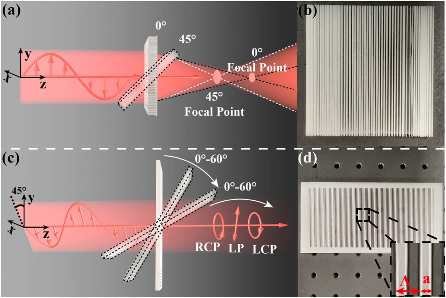
    Fig. 1. (a) Schematic of multifunctional wavefront shaping via the rotation of the cylindrical metalens composed of nonuniform gratings. The focal length shifts with the incident angle. (b) Photograph of the metalens. (c) Schematic of multifunctional polarization control via the rotation of the uniform grating around the x axis. The incident beam is polarized along 45° relative to the grating ridges. By changing the incident angle from 0° to 60°, the output polarization state can be switched among RCP, cross-LP, and LCP. (d) Photograph of the uniform grating for polarization control. The inset defines the period and the ridge width.
    Modulation of angular dispersion in gratings by tuning the number of excited waveguide modes. (a) Field distribution in a grating with Λ=0.47λ and η=0.73 with the mode matrix of [1, 1]. (b) Field distribution in a grating with Λ=0.56λ and η=0.7 with the mode matrix of [1, 2]. (c) Field distribution in a grating with Λ=0.93λ and η=0.58 with the mode matrix of [2, 2]. The position of the grating is shown by the dash box in (a)–(c). The field in the grating is decomposed into separate waveguide modes if more than one mode is excited in (a)–(c). (d)–(f) Solid lines show variation of the transmission phase over the incident angle for the gratings in (a)–(c). Dash lines are the transmission phase of gratings with changed duty cycle and the same mode matrix. (g) Independent transmission phases achieved at 0° and 45° incident angles in 64 types of gratings. (h) Period distribution of the 64 gratings. (i) Duty cycle distribution of the 64 gratings.
    Fig. 2. Modulation of angular dispersion in gratings by tuning the number of excited waveguide modes. (a) Field distribution in a grating with Λ=0.47λ and η=0.73 with the mode matrix of [1, 1]. (b) Field distribution in a grating with Λ=0.56λ and η=0.7 with the mode matrix of [1, 2]. (c) Field distribution in a grating with Λ=0.93λ and η=0.58 with the mode matrix of [2, 2]. The position of the grating is shown by the dash box in (a)–(c). The field in the grating is decomposed into separate waveguide modes if more than one mode is excited in (a)–(c). (d)–(f) Solid lines show variation of the transmission phase over the incident angle for the gratings in (a)–(c). Dash lines are the transmission phase of gratings with changed duty cycle and the same mode matrix. (g) Independent transmission phases achieved at 0° and 45° incident angles in 64 types of gratings. (h) Period distribution of the 64 gratings. (i) Duty cycle distribution of the 64 gratings.
    (a) Ideal phase profiles of the metalens with 150 mm focal length (purple line) at 0° incident angle and 100 mm focal length (yellow line) at 45° incident angle. Dots are discrete phase distribution of the selected grating units under different incident angles. (b) Simulated field distribution with 0° excitation using Lumerical FDTD Solutions. (c) Measured field distribution with 0° excitation. (d) Simulated field distribution with 45° excitation using Lumerical FDTD Solutions. (e) Measured field distribution with 45° excitation.
    Fig. 3. (a) Ideal phase profiles of the metalens with 150 mm focal length (purple line) at 0° incident angle and 100 mm focal length (yellow line) at 45° incident angle. Dots are discrete phase distribution of the selected grating units under different incident angles. (b) Simulated field distribution with 0° excitation using Lumerical FDTD Solutions. (c) Measured field distribution with 0° excitation. (d) Simulated field distribution with 45° excitation using Lumerical FDTD Solutions. (e) Measured field distribution with 45° excitation.
    Variation of the transmission phase of (a) TE and (b) TM polarizations with the incident angle and the grating period when η=0.4 and h=5.2 mm. To better observe the phase change with the incident angle, the phases at θ=0° are forced to be 0 in both plots. (c) Variation of the phase difference δϕ between TE and TM polarizations with the grating period and the incident angle. (d) δϕ in selected gratings with period of Λ=0.4 mm, Λ=0.7 mm, Λ=1.0 mm, and Λ=1.4 mm.
    Fig. 4. Variation of the transmission phase of (a) TE and (b) TM polarizations with the incident angle and the grating period when η=0.4 and h=5.2  mm. To better observe the phase change with the incident angle, the phases at θ=0° are forced to be 0 in both plots. (c) Variation of the phase difference δϕ between TE and TM polarizations with the grating period and the incident angle. (d) δϕ in selected gratings with period of Λ=0.4  mm, Λ=0.7  mm, Λ=1.0  mm, and Λ=1.4  mm.
    Simulated and experimentally measured intensity distribution by rotating the polarizer before the detector with and without the gratings with different incident angles realized by tilting the sample.
    Fig. 5. Simulated and experimentally measured intensity distribution by rotating the polarizer before the detector with and without the gratings with different incident angles realized by tilting the sample.
    Simulated and experimentally measured intensity modulation by electrically rotating the grating and inserting a polarizer.
    Fig. 6. Simulated and experimentally measured intensity modulation by electrically rotating the grating and inserting a polarizer.
    Yiwu Yuan, Jierong Cheng, Fei Fan, Xianghui Wang, Shengjiang Chang. Control of angular dispersion in dielectric gratings for multifunctional wavefront shaping and dynamic polarization conversion[J]. Photonics Research, 2021, 9(11): 2190
    Download Citation