
Yiwu Yuan, Jierong Cheng, Fei Fan, Xianghui Wang, Shengjiang Chang. Control of angular dispersion in dielectric gratings for multifunctional wavefront shaping and dynamic polarization conversion[J]. Photonics Research, 2021, 9(11): 2190
- Photonics Research
- Vol. 9, Issue 11, 2190 (2021)
Abstract
1. INTRODUCTION
Angular dispersion characterizes the variation of the electromagnetic response with the incident angle. Traditional metasurfaces are focused on electromagnetic manipulation at a specific incident angle [1–5]. The angular dispersion is either overlooked or very weak. Until recently, researches are carried out to intentionally weaken it for angle-insensitive functionalities [6–8] and to maximize it for angle-dependent wave manipulation [9–12] and angle-multiplexed multifunctionalities [13–16]. Precisely tailoring the angular dispersion offers a new degree of freedom for wave manipulation.
Angular dispersion has been proved to be closely related to the near-field coupling among adjacent meta-elements. To reduce the angular sensitivity, one should weaken the coupling of the elements. For example, Deng et al. showed that the localized cavity mode resonance of the reflective metallic grating is unchanged with the variation of the incident angle [6]. Zhang et al. used the dislocated metallic bars with reduced inter-element coupling to achieve angle-insensitive meta-absorbers [17]. In contrast, angular dispersion can be enhanced in strongly coupled metasurfaces and even finely tuned by controlling the coupling strength. Collective resonances in tightly coupled split rings show ultrahigh angular selectivity [18,19], which can be used to suppress the stray light, to increase the sensitivity of detectors, to function as spatial frequency filters [20,21], and to perform analog computing [22]. A metasurface operating in the bound states in the continuum with angle-tunable resonances is used for spectrum detection [15].
In addition, the nonlocal interaction is also helpful to increase the angular dispersion. We have shown that long-period metasurfaces with nonlocal scattering can selectively enhance the diffraction in a desired order according to different incident angles [23]. Disordered metasurfaces greatly reduce the memory effect and shape the wavefront into completely different patterns with a tiny change of the incident angle [24]. Topology-optimized freeform metasurfaces with implicit coupling show angle-tunable birefringence for versatile polarization control [10]. The coupling and interaction in the above designs happen in a much longer distance as compared to that in metasurfaces with rigorous subwavelength lattice, facilitating the realization of multifunctional integration encoded by the incident angle.
Sign up for Photonics Research TOC. Get the latest issue of Photonics Research delivered right to you!Sign up now
In this work, we tailor the angular dispersion from another perspective. We focus on the simplest one-dimensional binary dielectric grating structure and find the physical origin of angular dispersion from the contribution of waveguide modes to the transmission response. One can independently manipulate the zeroth-order transmission phases from different incident angles by properly tuning the number of waveguide modes inside the grating. In addition, low-index dielectric structure is used as it brings stronger angular dispersion as compared to the high-index one due to the weak field localization and increased coupling [14]. A metalens is designed and experimentally verified with independent focal lengths at two incident angles. We further utilize the angular dispersion in TE and TM modes to demonstrate angle-insensitive wave plates and angle-multiplexed trifunctional wave plates. All the samples are 3D-printed and tested at terahertz frequencies with excellent performance. The simple structure, clear physics, and low-cost fabrication technique make the dielectric grating an attractive choice for multifunctional wavefront and polarization control encoded in well-tailored angular responses.
2. MECHANISM OF TAILORING THE ANGULAR DISPERSION
The angle-dependent wavefront shaping and polarization control are schematically shown in Figs. 1(a) and 1(c), which are implemented by rotating one-dimensional nonuniform and uniform dielectric gratings around the axis, respectively. The grating is made of low-index and low-loss 3D-printable polymer high impact polystyrene (HIPS) with refractive index of 1.518 around the target frequency 0.14 THz. The geometric parameters of the grating involve the period , the duty cycle of the ridge , and the thickness . For angle-dependent wavefront shaping, both and vary along the axis, and is fixed, while the grating is uniform for polarization control.
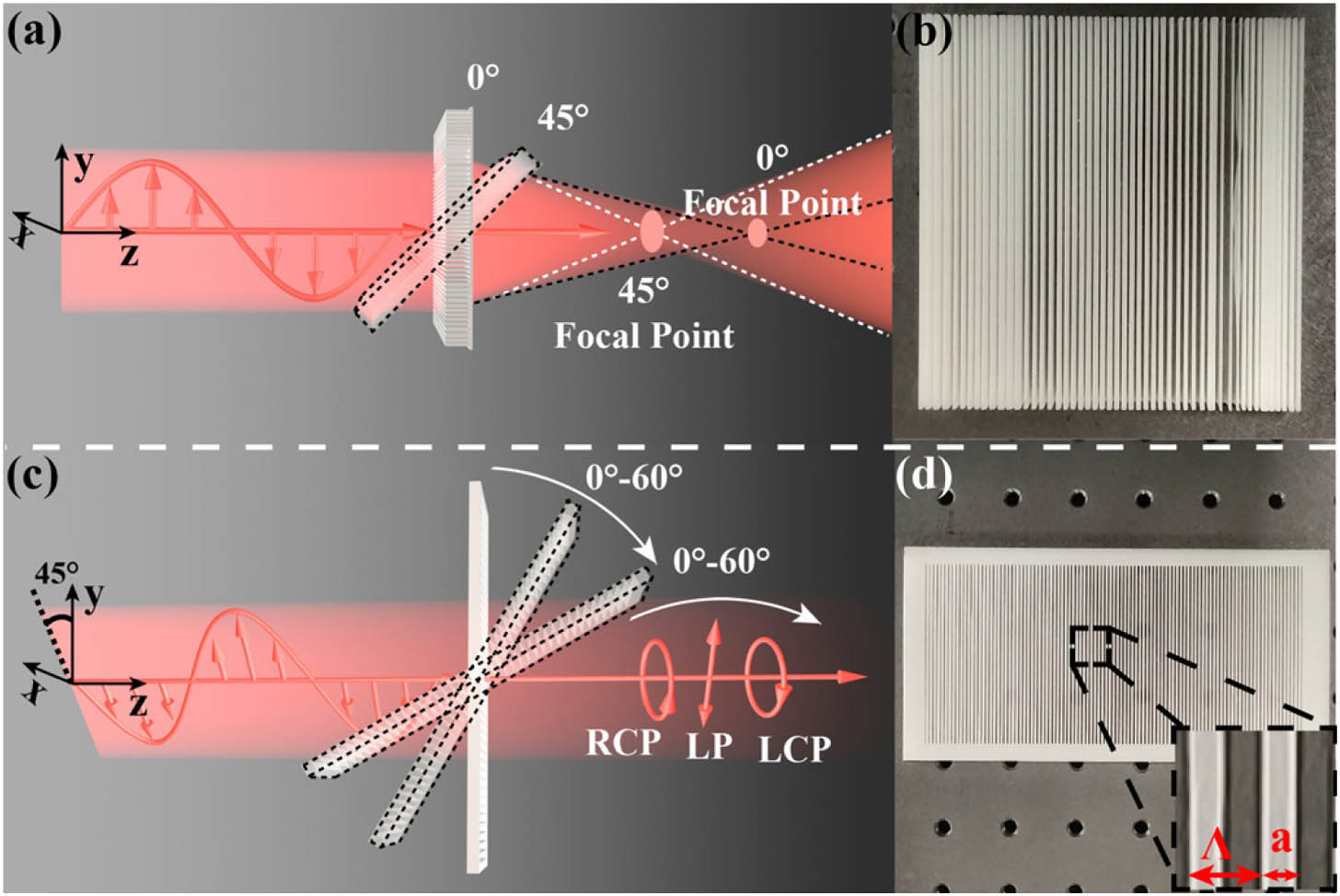
Figure 1.(a) Schematic of multifunctional wavefront shaping via the rotation of the cylindrical metalens composed of nonuniform gratings. The focal length shifts with the incident angle. (b) Photograph of the metalens. (c) Schematic of multifunctional polarization control via the rotation of the uniform grating around the
To explain the origin of angular dispersion and the method of controlling it, we consider the uniform grating as a periodic waveguide truncated along the axis and analyze the supported Bloch waveguide modes. Considering the TM polarization as an example, the field in and out of the grating can be written in a general form [25,26]:
The summation of the waveguide modes is matched to the transmission and reflection fields at the bottom and top interfaces. One can obtain the diffracted fields of each order by doing the Fourier decomposition of the total field at the interfaces. When reflection is ignored, the zeroth-order diffraction coefficient (noted as for short) can be expressed as
For clarity, we define a mode matrix for each grating with two elements describing the number of supported waveguide modes corresponding to incident angles of and . We find that if two gratings have the same mode matrix, their angular responses share very similar shapes with a constant shift. It means the phase difference between two incident angles is locked, and the angular dispersion cannot be tuned freely. In contrast, changing one or two elements in by tuning the geometric parameters and means introduction of new waveguide modes. Hence the transmission response in Eq. (2) is disturbed by the addition of new modes, and the shape of the curve can be dramatically changed. The angular dispersion can be tailored accordingly.
Here we consider and for simplicity and analyze the angular dispersion of three gratings with different mode matrices . The first grating has the period and duty cycle . It supports one waveguide mode regardless of the launched direction of the beam, corresponding to the mode matrix of . The field distributions at two incident angles are shown in Fig. 2(a). The grating behaves as an effective medium and refracts the beam at the interfaces. The second grating with and has the mode matrix of . The field inside the grating is composed of two modes with 45° excitation as shown in Fig. 2(b). The third grating with and has another mode matrix of . The field distribution in the grating layer is superposition of two waveguide modes both with normal excitation and with 45° excitation. The angular response of the zeroth-order transmission phase of the three gratings is summarized in Figs. 2(d)–2(f). The slope of is different from each other. is always 0, and is , , and in the three cases. In contrast, if we simply change the duty cycle of each grating while maintaining its mode matrix, only gains a constant phase shift as shown by the dash curves in Figs. 2(d)–2(f). This means the angular dispersion is hardly tunable if only one type of mode matrix is involved.
![]()
Figure 2.Modulation of angular dispersion in gratings by tuning the number of excited waveguide modes. (a) Field distribution in a grating with
Higher-order modes always appear first when the incident angle is larger. With the increase of the grating period, the involved matrices are [1, 1], [1, 2], and [2, 2] in sequence. With further increase of the grating period, the next matrix will be [2, 3]. So in order to decouple the responses from different incident angles, it is better to involve as many mode matrices as possible in the process of adjusting geometric parameters, sometimes at the cost of opening higher diffraction orders [Fig. 2(c)]. However, the choice of the grating should minimize the energy in higher diffraction orders and in the reflection side to ensure the efficiency in angular dispersion engineering. Since variation of the thickness does not change the number of the waveguide mode, it is not a key factor to tune the angular dispersion. For simplicity, we choose for proper phase manipulation at normal incidence, and we tune and to tailor the angular dispersion.
By simultaneously tuning the period and the duty cycle, one can independently tune the phase responses under different incident angles. The grid in Fig. 2(g) shows all the combinations of and in the range of with a step of , when and . The dots are realized by 64 gratings, which sit at or around the desired grid points. The period and duty cycle of the 64 gratings are shown in Figs. 2(h) and 2(i). The efficiency of the zeroth-order transmission is above 0.5 in all the cases. The involved mode matrices are [1, 1], [1, 2], and [2, 2]. All the gratings in Fig. 2 have the thickness of . They are thicker than conventional metasurfaces partly due to the use of low-index dielectric and partly due to the need of independent control of phase responses at different incident angles.
All the above analysis is under TM polarization. For TE-polarized excitation, the involved mode matrices may be different from the TM case due to the anisotropic feature of the one-dimensional grating. Manipulation of the angular dispersion of the phase retardation between TM and TE polarization states will be more flexible as one has more choices to combine different mode matrices in TM and TE polarizations. Next, angle-dependent wavefront shaping in TM polarization and angle-insensitive/sensitive polarization control are studied to demonstrate the power of the simple grating structure in tailoring the angular dispersion on demand.
3. ANGLE-DEPENDENT WAVEFRONT SHAPING
To demonstrate the flexibility of wavefront shaping brought by angular dispersion, we design a cylindrical metalens with different focal lengths when illuminated from different directions. The operation frequency is set as 140 GHz. Figure 3(a) shows the phase profile of the metalens when the focal length is 150 mm with 0° excitation and 100 mm with 45° excitation. According to the data in Figs. 2(h) and 2(i), gratings with different and are selected and arranged spatially to simultaneously satisfy the desired phase responses for 0° and 45° excitations. The discrete circles in Fig. 3(a) show that the gratings are not equally spaced as what we usually have in conventional metasurfaces.
![]()
Figure 3.(a) Ideal phase profiles of the metalens with 150 mm focal length (purple line) at 0° incident angle and 100 mm focal length (yellow line) at 45° incident angle. Dots are discrete phase distribution of the selected grating units under different incident angles. (b) Simulated field distribution with 0° excitation using Lumerical FDTD Solutions. (c) Measured field distribution with 0° excitation. (d) Simulated field distribution with 45° excitation using Lumerical FDTD Solutions. (e) Measured field distribution with 45° excitation.
The metalens is fabricated by a 3D printer (RAISE3D N2) using the fused-deposition modeling (FDM) method as shown in Fig. 1(b). The simulated and experimentally measured intensity distributions are summarized in Figs. 3(b)–3(e). With normal excitation, the simulated focal length is 138 mm, and the measured one is 125 mm. 45° excitation is achieved by rotating the metalens around the axis by 45°. The simulated and measured focal lengths are 95 mm and 91 mm, respectively. Rotation of the metalens from 0° to 45° continuously shifts the focus from 125 mm to 91 mm, which can be used for dynamic 3D imaging. Since the metalens is relatively thick, the alignment between the metalens and the Gaussian beam has an impact on the field distribution for the oblique incidence. The simulation shows the best focusing performance when the top surface center of the metalens is at , which is also the reason for the asymmetry of the focus in Fig. 3(d), while the measurement shows the best focusing when the center of the whole volume is aligned to . We attribute this discrepancy to the fabrication error of the metalens and the system alignment error. Further study shows that the bandwidth of the metalens is wider under normal excitation than under oblique excitation. This is because the phase of the grating under oblique excitation is a result of two-mode interference, which oscillates with frequency.
4. ANGLE-INSENSITIVE/MULTIPLEXED POLARIZATION CONTROL
For polarization control, the duty cycle of the grating is fixed as 0.4, because the form birefringence will be reduced as is towards 0 or 1. The thickness of the grating is fixed as 5.2 mm. Figures 4(a)–4(c) show the transmission phase in TE and TM polarizations and the phase retardation between TE and TM with the variation of grating periods and incident angles. The pseudo color plots are divided by the dashed lines into two parts, corresponding to one and two waveguide modes supported in the gratings, respectively, in Figs. 4(a)–4(c). In the one-mode region, although the phase of both TE and TM polarizations varies with the incident angle, the phase difference is quite stable regardless of and . In the two-mode region, varies quickly with the incident angle. With being 0.4, 0.7, and 1 mm, the angular responses of are shown in Fig. 4(d). The slope of is weakly modulated among the three gratings, as they all support a single waveguide mode for each polarization with incident angles up to 60°. Especially when is 0.7 mm, is invariant with the incident angle . This grating can be used as an angle-insensitive quarter-wave plate for linear-circular polarization conversion. The thickness of the grating is chosen to have a phase retardation of . One can simply double the thickness to achieve an angle-insensitive half-wave plate with .
![]()
Figure 4.Variation of the transmission phase of (a) TE and (b) TM polarizations with the incident angle and the grating period when
To significantly deviate from the current angular dispersion, a larger grating period can be chosen so that more waveguide modes will appear for oblique incidence. For example, when is 1.4 mm, there are two waveguide modes, as the incident angle is larger than 20°. Figure 4(d) shows that vibrates and increases significantly with , leading to phase retardation of , , and when is 0°, 45°, and 56°, respectively. As a result, the grating with can switch the linear polarization into right-handed circular (RCP), cross-polarized linear (LP), and left-handed circular (LCP) polarization states by simply rotating the sample. If we still consider two incident angles and , the mode matrix is [1, 1] in the angle-insensitive grating and [1, 2] in the highly dispersive grating. When working at other frequencies around 0.14 THz, the grating with still has an angle-insensitive , which varies proportionally with frequency. The grating with shows increased (decreased) angular dispersion when working at higher (lower) frequencies.
For validation, we 3D-print and experimentally test two gratings with being 0.7 mm and 1.4 mm at 0.14 THz. One sample with is shown in Fig. 1(d). Figure 5 shows the intensity of the beam by rotating the polarizer before the detector without and with the grating samples. The measured results are well consistent with the theoretical ones. The source is linearly polarized along 45° in the plane as shown in Fig. 1(c). The grating with is a quarter-wave plate converting the linear polarization into the circular one insensitive to the incident angle except for the very large angle of 56°. In contrast, the grating with is very sensitive to the incident angle. The output polarization varies from circular to cross-linear and then opposite-handed circular states with the increase of the incident angle. The transmission efficiency towards the zeroth order is above 90% for both gratings under four incident angles, except for the grating with at 45° and 56°, where the efficiency is 80%.
![]()
Figure 5.Simulated and experimentally measured intensity distribution by rotating the polarizer before the detector with and without the gratings with different incident angles realized by tilting the sample.
Next, we fix the polarization axis of the polarizer to be the same as the incident polarization direction. The dispersive grating wave plate is mounted on a motorized rotation stage for dynamic intensity modulation with a rotation speed of 60° per second. The measured and simulated intensity variations with the incident angle are shown in Fig. 6. The detected intensity is 0.46 for normal excitation and 0.03 for 45° excitation, respectively, which further validates that the output is very close to circular and cross-linear polarization states. The variation of the transmission is slow around 0° and 180°, as the phase retardation varies slowly for small-angle excitation as shown in Fig. 4(d). The intensity can be modulated between 0 and 0.62. The grating shows great potential as an electrical terahertz (THz) modulator with the modulation speed controlled by the rotation speed.
![]()
Figure 6.Simulated and experimentally measured intensity modulation by electrically rotating the grating and inserting a polarizer.
5. CONCLUSION
In conclusion, we propose a strategy to tune the angular dispersion of dielectric binary gratings by controlling the number of waveguide modes inside the grating. We show that the transmission phase is highly correlated with the incident angle in different gratings if they support the same number of waveguide modes. This correlation can be broken by introducing new waveguide modes, which facilitates completely independent wavefront shaping and multifunctional polarization conversion over different incident angles. Using this strategy, we experimentally demonstrate a metalens with angle-dependent focus, an angle-insensitive wave plate, and an angle-multiplexed wave plate, which can dynamically change the output to right-handed circular, cross-linear, and left-handed circular polarizations via electrical rotation of the grating. Our findings may extend the capability of metasurfaces in beam manipulation and promote the integration of multifunctionalities via the perspective of incident angle.
References
[1] J. Hu, S. Bandyopadhyay, Y. H. Liu, L. Y. Shao. A review on metasurface: from principle to smart metadevices. Front. Phys., 8, 1-20(2021).
[2] S. Chen, W. Liu, Z. Li, H. Cheng, J. Tian. Metasurface-empowered optical multiplexing and multifunction. Adv. Mater., 32, 1805912(2020).
[3] Q. He, S. Sun, S. Xiao, L. Zhou. High-efficiency metasurfaces: principles, realizations, and applications. Adv. Opt. Mater., 6, 1800415(2018).
[4] Z. Shen, S. Zhou, X. Li, S. Ge, P. Chen, W. Hu, Y. Lu. Liquid crystal integrated metalens with tunable chromatic aberration. Adv. Photon., 2, 036002(2020).
[5] B. Xu, H. Li, S. Gao, X. Hua, C. Yang, C. Chen, F. Yan, S. Zhu, T. Li. Metalens-integrated compact imaging devices for wide-field microscopy. Adv. Photon., 2, 066004(2020).
[6] Z. L. Deng, S. Zhang, G. P. Wang. A facile grating approach towards broadband, wide-angle and high-efficiency holographic metasurfaces. Nanoscale, 8, 1588-1594(2016).
[7] Y. Cheng, H. Zou, J. Yang, X. Mao, R. Gong. Dual and broadband terahertz metamaterial absorber based on a compact resonator structure. Opt. Mater. Express, 8, 3104-3114(2018).
[8] M. Feng, Y. Li, J. Zhang, Y. Han, J. Wang, H. Ma, S. Qu. Wide-angle flat metasurface corner reflector. Appl. Phys. Lett., 113, 143504(2018).
[9] X. Wang, A. Diáz-Rubio, S. A. Tretyakov. Independent control of multiple channels in metasurface devices. Phys. Rev. Appl., 14, 024089(2020).
[10] Z. Shi, A. Y. Zhu, Z. Li, Y. W. Huang, Y. W. Huang, W. T. Chen, C. W. Qiu, F. Capasso. Continuous angle-tunable birefringence with freeform metasurfaces for arbitrary polarization conversion. Sci. Adv., 6, eaba3367(2020).
[11] Y. Li, J. Yang, Z. Yin, G. Deng, W. Lai, X. Wang, D. Zhang, Q. Zhu. Angle-dispersive metasurface for axisymmetric wavefront manipulation over continuous incident angles. Phys. Rev. Appl., 14, 031001(2020).
[12] D. Arslan, K. E. Chong, A. E. Miroshnichenko, D.-Y. Choi, D. N. Neshev, T. Pertsch, Y. S. Kivshar, I. Staude. Angle-selective all-dielectric Huygens’ metasurfaces. J. Phys. D, 50, 434002(2017).
[13] E. Wang, J. Niu, Y. Liang, H. L. Li, Y. Hua, L. Shi, C. Xie. Complete control of multichannel, angle-multiplexed, and arbitrary spatially varying polarization fields. Adv. Opt. Mater., 8, 1901674(2020).
[14] S. M. Kamali, E. Arbabi, A. Arbabi, Y. Horie, M. S. Faraji-Dana, A. Faraon. Angle-multiplexed metasurfaces: encoding independent wavefronts in a single metasurface under different illumination angles. Phys. Rev. X, 7, 041506(2017).
[15] A. Leitis, A. Tittl, M. Liu, B. H. Lee, M. B. Gu, Y. S. Kivshar, H. Altug. Angle-multiplexed all-dielectric metasurfaces for broadband molecular fingerprint retrieval. Sci. Adv., 5, eaaw2871(2019).
[16] S. Li, X. Li, L. Zhang, G. Wang, L. Zhang, M. Liu, C. Zeng, L. Wang, Q. Sun, W. Zhao, W. Zhang. Efficient optical angular momentum manipulation for compact multiplexing and demultiplexing using a dielectric metasurface. Adv. Opt. Mater., 8, 1901666(2020).
[17] X. Zhang, Q. Li, F. Liu, M. Qiu, S. Sun, Q. He, L. Zhou. Controlling angular dispersions in optical metasurfaces. Light Sci. Appl., 9, 76(2020).
[18] M. Qiu, M. Jia, S. Ma, S. Sun, Q. He, L. Zhou. Angular dispersions in terahertz metasurfaces: physics and applications. Phys. Rev. Appl., 9, 054050(2018).
[19] N. Born, I. Al-Naib, C. Jansen, R. Singh, J. V. Moloney, M. Scheller, M. Koch. Terahertz metamaterials with ultrahigh angular sensitivity. Adv. Opt. Mater., 3, 642-645(2015).
[20] X. Chen, Z. Wang, W. Chen, Y. S. Ang, W. Y. Yin, H. Chen, E. P. Li. Magnetic metamirrors as spatial frequency filters. IEEE Trans. Antennas Propag., 68, 5505-5511(2020).
[21] V. A. Fedotov, J. Wallauer, M. Walther, M. Perino, N. Papasimakis, N. I. Zheludev. Wavevector selective metasurfaces and tunnel vision filters. Light Sci. Appl., 4, e306(2015).
[22] F. Zangeneh-Nejad, D. L. Sounas, A. Alù, R. Fleury. Analogue computing with metamaterials. Nat. Rev. Mater., 6, 207-225(2021).
[23] J. Cheng, S. Inampudi, H. Mosallaei. Optimization-based dielectric metasurfaces for angle-selective multifunctional beam deflection. Sci. Rep., 7, 12228(2017).
[24] M. Haghtalab, M. Tamagnone, A. Y. Zhu, S. Safavi-Naeini, F. Capasso. Ultrahigh angular selectivity of disorder-engineered metasurfaces. ACS Photon., 7, 991-1000(2020).
[25] Y. Yuan, J. Cheng, X. Dong, F. Fan, X. Wang, S. Chang. Terahertz dual-band polarization control and wavefront shaping over freestanding dielectric binary gratings with high efficiency. Opt. Laser Eng., 143, 106636(2021).
[26] T. Clausnitzer, T. Kämpfe, E.-B. Kley, A. Tünnermann, U. Peschel, A. V. Tishchenko, O. Parriaux. An intelligible explanation of highly-efficient diffraction in deep dielectric rectangular transmission gratings. Opt. Express, 13, 10448-10456(2005).
[27] V. Karagodsky, F. G. Sedgwick, C. J. Chang-Hasnain. Theoretical analysis of subwavelength high contrast grating reflectors. Opt. Express, 18, 16973-16988(2010).
[28] T. Clausnitzer, T. Kämpfe, E. B. Kley, A. Tünnermann, A. Tishchenko, O. Parriaux. Investigation of the polarization-dependent diffraction of deep dielectric rectangular transmission gratings illuminated in Littrow mounting. Appl. Opt., 46, 819-826(2007).

Set citation alerts for the article
Please enter your email address
© Copyright 2018-2021 | Chinese Laser Press. All Rights Reserved 沪ICP备15018463号-20