
Chengyang Hu, Honghao Huang, Minghua Chen, Sigang Yang, Hongwei Chen. FourierCam: a camera for video spectrum acquisition in a single shot[J]. Photonics Research, 2021, 9(5): 701
- Photonics Research
- Vol. 9, Issue 5, 701 (2021)
Abstract
1. INTRODUCTION
Humans observe the world in the space–time coordinate system, and traditional video cameras are also based on the same principle. The video data format in the unit of a time serial image frame is well understood for eyes and is the basis for many years of research in machine vision. With the development of optics, focal plane optoelectronics, and a post-detection algorithm, some novel video camera architectures have gradually emerged [1]. The single-shot ultrafast optical imaging system observes the transient events in physics and chemistry at an incredible rate of one billion frames per second (fps) [2]. An event camera with high dynamic range, high temporal resolution, and low power consumption asynchronously measures the brightness change, position, and symbol of each pixel to generate event streams and is widely used in autonomous driving, robotics, security, and industrial automation [3]. A privacy-preserving camera based on coded aperture has also been applied in action recognition [4]. Although the functions of these cameras are impressive, the essential sampling strategy is still to measure the reflected or transmitted light intensity of a scene in the temporal domain. In the lens system, pixels can be regarded as independent time channels, and the acquired signal is the temporal variation of light intensity at the corresponding position in the scene. It is well-known that the frequency domain feature of a visual temporal signal is more significant. For example, in general, a natural scene video has high temporal redundancies, so most information of a temporal signal concentrates on low-frequency components, which is a premise in video compression [5]. The static background of the scene appears as a DC component in the frequency domain, which provides insights for background subtraction [6–8]. In deep learning, performing high-level vision tasks based on spatial frequency domain data brings a better result [9]. By taking into account space–time duality, this strategy has the potential to be used for temporal frequency domain data. All of the above frequency characteristics imply that capturing video in the temporal frequency domain instead of the temporal domain will initiate a sampling revolution.
In this paper, we propose a temporal frequency sampling video camera: FourierCam, which is a novel architecture that innovates the basic sampling strategy. The concept of FourierCam is to perform pixel-wise optical coding on the scene video and directly obtain the temporal spectrum in a single shot. In contrast with the traditional cameras, the framework of single-shot temporal spectrum acquisition has a lower detection bandwidth. Furthermore, the data volume can be reduced by analyzing the temporal spectrum features for efficient sampling. Since the temporal Fourier transform is done in the optical system, its computational burden is lower compared to that of the time-frequency transformation pipeline (sampling–storing–transforming). In addition to the basic advantages, according to the clear physical meaning of the spectrum, a variety of temporal filter kernels can be designed to accomplish typical machine vision tasks. To demonstrate the capability of FourierCam, we present a series of applications, which cover video compression, background subtraction, object extraction, and trajectory tracking. These applications can be easily switched only by adjusting the temporal filter kernels without changing the system structure. As a flexible framework, FourierCam can be easily integrated with existing imaging systems and is suitable for microimaging to macroimaging.
2. PRINCIPLE OF FourierCam
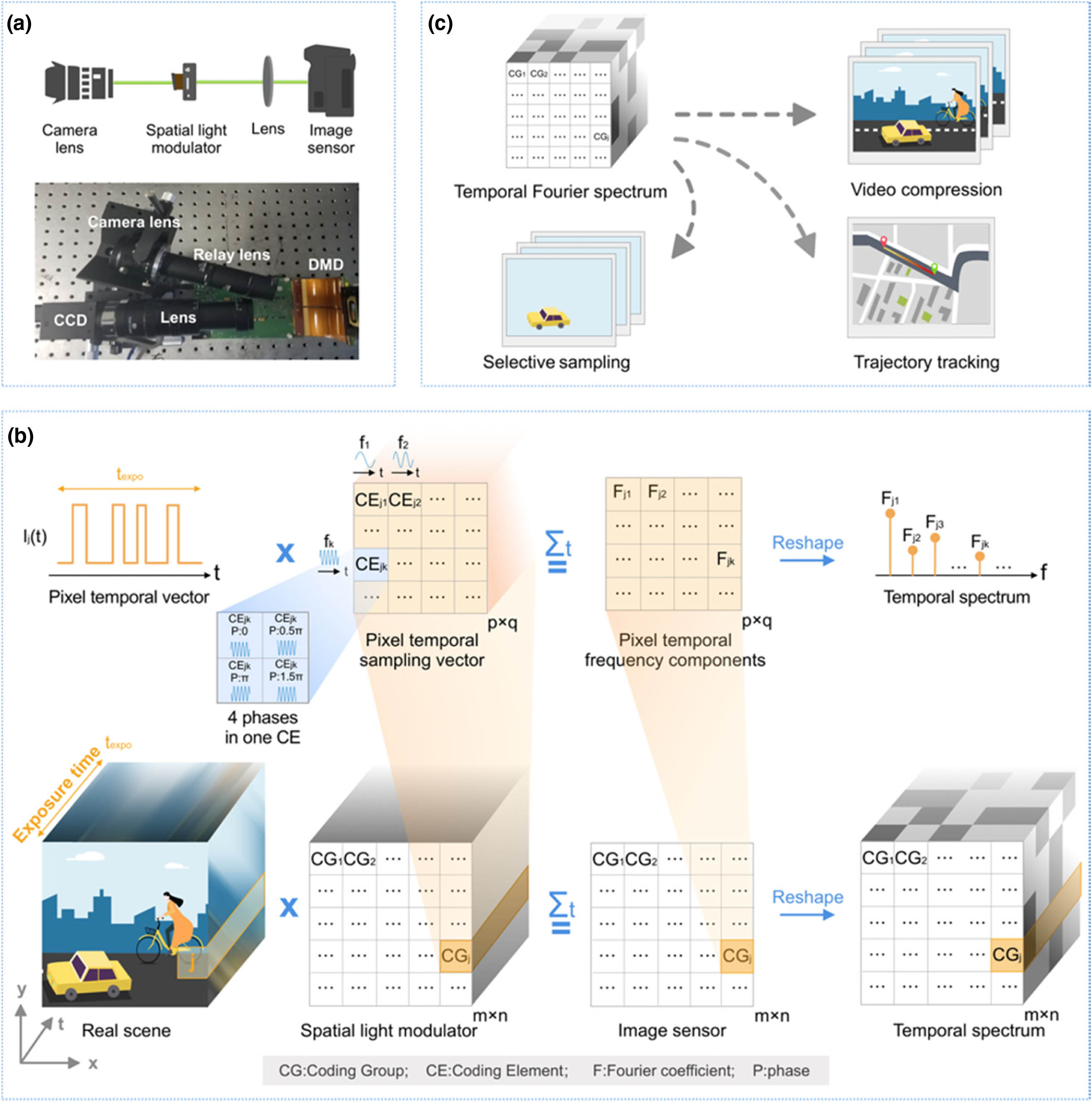
Figure 1.Overview of FourierCam. (a) Schematic and prototype of FourierCam. (b) Coding strategy of FourierCam. The real scene is coded by a spatial light modulator (DMD) and integrated during a single exposure of the image sensor. The DMD is spatially divided into coding groups (
In the experimental setup, the scene is imaged on a virtual plane through a camera lens (CHIOPT HC3505A). A relay lens (Thorlabs MAP10100100-A) transfers the image to the DMD (ViALUX V-9001, resolution, 7.6 μm pitch size) for light amplitude distribution modulation. The reflected light from the DMD is then focused onto an image sensor (FLIR GS3-U3-120S6M-C, resolution, 3.1 μm pitch size) by a zoom lens (Utron VTL0714V). Due to one DMD mirror being matched with image sensor pixels, the effective resolution is one-third of the resolution of the image sensor in both the horizontal and the vertical directions (i.e., ).
Sign up for Photonics Research TOC. Get the latest issue of Photonics Research delivered right to you!Sign up now
The principle of the proposed FourierCam system is spatially splitting the scene into independent temporal channels and acquiring the temporal spectrum by the corresponding CG for each channel. Every CG contains some CEs to obtain Fourier coefficients for frequencies of interest. During one exposure time , the detected value in CE , CG is equivalent to an inner product of pixel temporal vector and pixel temporal sampling vector :
Based on the aforementioned principle of FourierCam, the temporal spectrum of the scene can be easily obtained. As a novel camera architecture with a special data format, FourierCam is of the following three advantages (see Appendix B for details).
Here, we introduce three applications to demonstrate these advantages of FourierCam [illustrated in Fig. 1(c)]. The first application is video compression. We verify the temporal spectrum acquisition of FourierCam and demonstrate the video compression by using the low-frequency-concentration property of the natural scene. The second application is selective sampling. We show the FourierCam is able to subtract the static background, as well as extract the objects with a specific texture, motion period, or speed by applying designed temporal filter kernels to process the signals during sensing. The last application is trajectory tracking. The temporal phase reveals the time order of events so the FourierCam can be used to analyze the presence and trajectory of the moving objects. These applications show that the temporal spectrum acquired by FourierCam, as a new format of visual information, is able to provide physical features to assist and complete vision tasks.
3. TEMPORAL SPECTRUM ACQUISITION: BASIC FUNCTION AND VIDEO COMPRESSION
The basic spectrum acquisition function of FourierCam is demonstrated. For ordinary aperiodic moving objects or natural varying scenes, the energy in the temporal spectrum is mainly concentrated at low frequencies. This observation is exploited to record compressive video in the temporal domain by only acquiring the Fourier coefficients of low frequencies using FourierCam.
By using the above method, we assemble the Fourier coefficient of in CG . We can combine all Fourier coefficients in CG to form its temporal spectrum as
![]()
Figure 2.Capturing aperiodic motion video using FourierCam. (a) Illustration of experiment setup and coding pattern on DMD. Each CG contains nine CEs (
The first demonstrative scene in this application includes a toy car running in the field of view. A capture of the static toy car is shown in Fig. 2(b) (top left) as ground truth. The coded data acquired by FourierCam is shown in Fig. 2(b) (top right) in which the scene is blurred and features of the toy car cannot be visually distinguished. After decoding, the complex temporal spectrum of the scene can be extracted. The corresponding amplitude and phase are shown in Fig. 2(b) (middle row) with their zoom-in view (bottom row). In addition to the toy car with a translating motion, a rotating object is also used for demonstration. This scene is a panda pattern on a rotating disk with an angular velocity of . In Fig. 2(c), the static capture of the object (top left), coded data (top right), amplitude, and phase (middle row) are shown respectively.
To visually evaluate the correctness of the acquired temporal spectra, the videos of the two scenes are reconstructed using the inverse Fourier transform. Figure 2(d) displays three frames from the video of the toy car (left column) and the rotating panda (right column). These results clearly show the statuses of the dynamic scenes at different times and indicate that FourierCam is able to correctly acquire the temporal spectrum. As the single-shot detection data includes the information of multiple frames (16 frames for demonstration), FourierCam realizes the effect of (16×) video compression. (See Appendix D for the numerical analysis about the performance of video compression. The reconstructed toy car video is shown as an example in
4. SELECTIVE SAMPLING: FLEXIBLE TEMPORAL FILTER KERNELS
FourierCam provides the flexibility for designing the combination of frequencies to be acquired, which is termed temporal filter kernels in this paper. By considering the prior of the scenes and objects, one can achieve selectively sampling the object of interest. In this part, three scenes are demonstrated: periodic motion video acquisition, static background subtraction, and object extraction based on speed and texture.
Periodic motions widely exist in medical, industry, and scientific research, such as heartbeat, rotating tool bit, and vibration. Since a periodic signal contains energy only in the direct current, fundamental frequency, and harmonics, it has a very sparse representation in the Fourier domain (see Appendix E for details). By taking the temporal spectrum characteristics into account as prior information, we use FourierCam to selectively acquire several principal frequencies in the temporal spectrum.
![]()
Figure 3.Capturing periodic motion video using FourierCam. (a) To capture a periodic motion with four frequencies, each CG contains four CEs (
Subtracting the background and extracting moving objects are significant techniques for video surveillance and other video processing applications. In the frequency domain, the background is concentrated on the DC component. By filtering the DC component, one can subtract the background and extract moving objects. Some moving object extraction approaches performed in the frequency domain [6–8] have been proposed, which need to acquire the video first and then perform Fourier transform, and thus suffer from relatively high computational cost and low efficiency. Thanks to the capability of FourierCam to directly acquire specific temporal spectral components in the optical domain, it can overcome the drawbacks of the aforementioned methods. In addition to subtracting the background, preanalysis on the temporal spectrum profile of the objects of interest gives the prior for one to design coding patterns for FourierCam to realize specific object extraction.
![]()
Figure 4.Object extraction by FourierCam. (a) Illustration of object extraction. The coding frequencies are based on the spectrum of the objects of interest. In this demonstration, the four rings on the disk are regarded as four objects of interest. Each ring only contains one frequency so that one CE is used in one CG. (b) Left: reference static scene with a disk and a poker card. The disk is rotating when capturing, and the four rings share the same rotating speed. Four right columns: FourierCam captured data for four rings extraction and corresponding results. For each extracted ring, other rings and static poker card are neglected. (c) Results for two identical rings rotating at different speed (1980 and 800 r/min, respectively). FourierCam enables extraction of a specific one out of these two rings.
The results show that FourierCam enables background subtraction and object extraction based on the temporal spectrum difference. Although only one frequency was used in the experiment, in principle it allowed using multiple frequencies to reconstruct more complex scenes, as long as the spectral difference is sufficiently obvious. It is worth noting that in some special cases objects with different textures and speeds may have the same spectral features, making FourierCam fail to distinguish them (see Appendix F for details).
5. TEMPORAL PHASE: TRAJECTORY TRACKING
Object detection and trajectory tracking for a fast-moving object have found important applications in various fields. In general, object detection is to determine the presence of an object, and object tracking is to acquire the spatial–temporal coordinates of a moving object. For the temporal waveform of a pixel where the object would pass by, the moving object takes the form of a pulse at a specific time. As the object is moving, the temporal waveforms at different spatial positions are of different temporal pulse positions, resulting in a phase shift in their temporal spectra. Since Fourier transform is a global-to-point transformation, one can extract the information of the presence and position of the pulse in the temporal domain from the amplitude and phase of a single Fourier coefficient. From this perspective, one can use FourierCam to determine the presence or/and simultaneously acquire the spatial trajectory and temporal position of a moving object.
To detect and track the moving object, only one frequency is needed to encode the scene. In this case, we let and . Thus, is the lowest resolvable frequency, and its Fourier coefficient provides sufficient knowledge of presence or/and motion of object. The amplitude of is , where denotes the absolute operation. As a static scene does not contain the component in the temporal spectrum, moving object detection can be achieved by applying a threshold on that an larger than the threshold indicates the presence of moving objects.
For moving object tracking, since the long exposure has already given the trace of the object, the phase of is utilized to further extract the temporal information: , where denotes the argument operation. A temporal waveform with a displacement of in the temporal domain results in a linear phase shift of in the temporal spectrum:
Therefore, the temporal displacement can be derived through
By applying the same operation to all CGs, we can extract the temporal information for all CGs and acquire the spatial–temporal coordinates of a moving object in the scene.
![]()
Figure 5.Moving object detection and tracking by FourierCam. (a) Only one frequency is needed to encode the scene for moving object detection and tracking. The period of sinusoidal coding signal is equal to the exposure time. Thus, only one CE is contained in each CG. (b) Coded data captured by FourierCam and tracking results. Left column: characters ‘T’, ’H’, ‘U’, ‘EE’ sequentially displayed by a screen with a 0.25 s duration for each. The color indicates the distribution of appearing time. Middle column: results for a displayed spot moving along a heart-shaped trajectory. Right column: results for two spots moving in circular trajectories with different radii. The spots are printed on a rotating disk driven by a motor.
6. DISCUSSION AND CONCLUSION
The main achievement of this work is the implementation of a high-quality temporal spectrum vision sensor that represents a concrete step toward the low detection bandwidth, low computational burden, and low data volume novel video camera architecture. In the experiment, we demonstrate the advantages of FourierCam in machine vision applications such as video compression, background subtraction, object extraction, and trajectory tracking. Among these applications, prior knowledge is not required for aperiodic video compression, background subtraction, and trajectory tracking (see Table 1 in Appendix H for details). These applications cover the most common scenarios and can be integrated with existing machine vision systems, especially autonomous driving and security [11]. The emergence of prior knowledge makes FourierCam lose some flexibility but gain better performance. Applications that require prior knowledge (periodic video compression and specific object extraction) have special scenarios (e.g., modal analysis of vibrations). Several engineering disciplines rely on modal analysis of vibrations to learn about the physical properties of structures. Relevant areas include structural health monitoring [12] and nondestructive testing [13,14]. These special scenarios are usually stable (i.e., require less flexibility) and allow better performance at a higher cost. Comparison Between Different Application for FourierCamApplication Prior Knowledge Scenario Coding Method Video compression × Normal Multifrequency coded signals depend on exposure time Selective sampling (Periodic motion video acquisition) Motion period Periodic Multifrequency coded signals depend on motion period Selective sampling (Background subtraction) × Normal Multifrequency DC components are not included Selective sampling (Object extraction) Temporal spectrum profile of the interest objects Normal Multifrequency coded signals depend on prior knowledge Trajectory tracking ✗ Normal Single-frequency coded signals depend on exposure time
It is worth mentioning that the FourierCam is built to enhance the flexibility of information utilization with the given limited data throughput. First, by taking the low-frequency properties of a natural scene, one can only sample the most significant low-frequency components to perform data compression during data acquisition with the frequency sampling flexibility of FourierCam. This compression based on frequency is similar to the JPEG [15] compression based on spatial frequency, that is, to store more significant information within limited data capability. In general, this is a kind of lossy compression, and it can also be lossless for some sparse scenes (such as periodic motion). Second, the FourierCam directly obtains the temporal spectrum as a special data type with abundant physical information of the dynamic scenes. Although the process that uses multiple DMD pixels and camera pixels to decode one frequency component brings data cost, the phase-shift operation of the multiple pixels can also reduce the background noise so that the quality of the data can be increased.
The temporal and spatial resolutions are the key parameters of the FourierCam. The temporal resolution (the highest frequency component that can be acquired) is determined by the bandwidth of the modulator. In the present optical system, the PWM mode reduces the DMD refresh rate. Zhang
APPENDIX A: CORRESPONDENCE BETWEEN DMD AND IMAGE SENSOR IN FourierCam
In the FourierCam the most important thing is to adjust each mirror of the DMD so as to correspond exactly to the pixel of the image sensor, such as CCD or CMOS. Under the premise of complete correspondence, FourierCam can achieve high-precision decoding. However, since the sizes of the CCD and DMD are very small, it is difficult to accurately align. Fortunately, CCD and DMD can be regarded as two gratings, so they can be aligned by observing the moiré fringes formed between them [
![]()
Figure 6.Phase analysis of the moiré fringe pattern obtained by the phase-shifting moiré method. (a) There are two errors: mismatch and misalignment. (b) Only mismatch error. (c) FourierCam with high-precision correspondence.
APPENDIX B: DETAILED DISCUSSION ABOUT FEATURES OF FourierCam
Assuming a video is captured by traditional cameras with M frames and N pixels in each frame, its data volume is bytes (assuming 1 byte for one pixel). FourierCam obtains Fourier components of the same video, and the data volume is bytes since a complex Fourier coefficient needs twice the capacity than a real number. Generally, M is larger than 2h. For example, in the “running dog” video in Appendix?
APPENDIX C: FRAME RATE AND FREQUENCY DOMAIN SAMPLING IN FourierCam
Traditional cameras can be regarded as the temporal-domain sampling process when capturing video, and the frame rate is the temporal sampling rate. Considering each pixel temporal waveform, given the frame rate, the highest frequency component, , that can be acquired is , where is the frame rate. Unlike the temporal-domain sampling process of traditional cameras, FourierCam is based on frequency-domain sampling. FourierCam directly acquires frequency components. When the highest frequency component it collects is , the equivalent frame rate of FourierCam is . In addition, the frequency domain sampling interval () of FourierCam needs to satisfy the frequency domain sampling theorem to ensure that the reconstructed video does not alias in the time domain. The frequency domain sampling interval is determined by the exposure time of the image detector (), . For example, the exposure time of an image detector is 1?s, and the frame rate is 1?Hz. If the frame rate is increased to 10?Hz, the frequency components to be acquired are 1?Hz, 2?Hz, 3?Hz, 4?Hz, and 5?Hz. Its frequency interval is 1?Hz, which satisfies the frequency domain sampling theorem.
APPENDIX D: QUANTITATIVE ANALYSIS ON THE PERFORMANCE OF FourierCam
To quantitatively evaluate the reconstruction, we perform a simulation of FourierCam with a “running dog” video, which has 100 frames with a spatial resolution of pixels. We obtain the temporal spectrum of the video with 16 frequencies (the number of acquired Fourier coefficients ). Figure?
![]()
Figure 7.Simulation of FourierCam video reconstruction. (a) Long exposure capture with all frames directly accumulating together, corresponding to a slow camera and the FourierCam encoded capture. The insets show the zoom-in view of the areas pointed by the arrows. (b) In the reconstructed video with 16 Fourier coefficients, the SSIM of each frame keeps stable with an average of 0.9126 and a standard deviation of 0.0107. (c) Three exemplar frames from the ground truth and reconstructed video.
![]()
Figure 8.Quantitative analysis on the performance of FourierCam. (a) Relation between number of acquired Fourier coefficients
APPENDIX E: FOURIER DOMAIN PROPERTIES OF PERIODIC AND APERIODIC MOTION
Consider the signal at a position where a periodic motion passes: it is in periodic form in time domain. Fourier transform of a periodic signal with period contains energy only at the frequencies that are an integer multiple of repetition frequency , and therefore the periodic signal has a sparse representation in the Fourier domain. When the period of the periodic signal becomes infinitely long, the periodic signal comes to an aperiodic signal with a single pulse and its spectrum becomes continuous. Figure?
![]()
Figure 9.Fourier domain properties of periodic and aperiodic signals. The (a) periodic signal has a (b) sparse spectrum while the (c) aperiodic signal has a (d) continuous spectrum.
APPENDIX F: TEMPORAL RESOLUTION OF OBJECT TRACKING IN FourierCam
As the object is moving, the temporal waveforms at different spatial positions are of different temporal pulse positions, resulting in a phase shift in their temporal spectra. The phase-shift detection accuracy is the temporal resolution of object tracking in FourierCam. The phase-shift accuracy is determined with the DMD grayscale level and the exposure time of the image detector, so the temporal resolution is . Since we use a DMD with PWM mode as the spatial light modulator in FourierCam, the light is digitally modulated by 8-bit grayscale. Therefore, during a single exposure , the temporal resolution of object tracking is .
APPENDIX G: FOURIER DOMAIN PROPERTIES OF MOVING OBJECT
Changes in both the texture and the speed of the moving object can cause a difference in the Fourier domain. As illustrated in Fig.?
![]()
Figure 10.Illustration of Fourier domain properties of moving objects with different texture and speed. (a) Block with sinusoidal fringe texture moving at a speed of
APPENDIX H: COMPARISON BETWEEN DIFFERENT APPLICATION FOR FourierCam
The comparison between different applications for FourierCam is shown in Table?
References
[1] J. N. Mait, G. W. Euliss, R. A. Athale. Computational imaging. Adv. Opt. Photon., 10, 409-483(2018).
[2] J. Liang, L. V. Wang. Single-shot ultrafast optical imaging. Optica, 5, 1113-1127(2018).
[3] G. Gallego, T. Delbruck, G. M. Orchard, C. Bartolozzi, B. Taba, A. Censi, S. Leutenegger, A. Davison, J. Conradt, K. Daniilidis, D. Scaramuzza. Event-based vision: a survey. IEEE Trans. Pattern Anal. Mach. Intell.(2021).
[4] Z. W. Wang, V. Vineet, F. Pittaluga, S. N. Sinha, O. Cossairt, S. B. Kang. Privacy-preserving action recognition using coded aperture videos. IEEE/CVF Conference on Computer Vision and Pattern Recognition Workshops (CVPRW), 1-10(2019).
[5] T. Ouni, W. Ayedi, M. Abid. New low complexity DCT based video compression method. International Conference on Telecommunications, 202-207(2009).
[6] W. Wang, J. Yang, W. Gao. Modeling background and segmenting moving objects from compressed video. IEEE Trans. Circuits Syst. Video Technol., 18, 670-681(2008).
[7] D.-M. Tsai, W.-Y. Chiu. Motion detection using Fourier image reconstruction. Pattern Recogn. Lett., 29, 2145-2155(2008).
[8] T.-H. Oh, J.-Y. Lee, I. S. Kweon. Real-time motion detection based on discrete cosine transform. 19th IEEE International Conference on Image Processing, 2381-2384(2012).
[9] K. Xu, M. Qin, F. Sun, Y. Wang, Y.-K. Chen, F. Ren. Learning in the frequency domain. IEEE/CVF Conference on Computer Vision and Pattern Recognition, 1740-1749(2020).
[10] D. Doherty, G. Hewlett. 10.4: phased reset timing for improved digital micromirror device (DMD) brightness. SID Symp. Dig. Tech. Papers, 29, 125-128(1998).
[11] S. Ojha, S. Sakhare. Image processing techniques for object tracking in video surveillance: a survey. International Conference on Pervasive Computing (ICPC), 1-6(2015).
[12] I. Ishii, S. Takemoto, T. Takaki, M. Takamoto, K. Imon, K. Hirakawa. Real-time laryngoscopic measurements of vocal-fold vibrations. Annual International Conference of the IEEE Engineering in Medicine and Biology Society, 6623-6626(2011).
[13] A. Davis, M. Rubinstein, N. Wadhwa, G. J. Mysore, F. Durand, W. T. Freeman. The visual microphone: passive recovery of sound from video. ACM Trans. Graph., 33, 79(2014).
[14] A. Davis, K. L. Bouman, J. G. Chen, M. Rubinstein, F. Durand, W. T. Freeman. Visual vibrometry: estimating material properties from small motion in video. IEEE/CVF Conference on Computer Vision and Pattern Recognition, 5335-5343(2015).
[15] G. Wallace. The JPEG still picture compression standard. IEEE Trans. Consum. Electron., 38, xviii-xxxiv(1992).
[16] Z. Zhang, X. Wang, G. Zheng, J. Zhong. Fast Fourier single-pixel imaging via binary illumination. Sci. Rep., 7, 12029(2017).
[17] L. Bian, J. Suo, X. Hu, F. Chen, Q. Dai. Efficient single pixel imaging in Fourier space. J. Opt., 18, 085704(2016).
[18] B. E. Bayer. Color imaging array. U.S. patent(1976).
[19] H. S. Malvar, L.-W. He, R. Cutler. High-quality linear interpolation for demosaicing of Bayer-patterned color images. IEEE International Conference on Acoustics, Speech, and Signal Processing, iii-485-8(2004).
[20] R. Ramanath, W. E. Snyder, G. L. Bilbro, W. A. Sander. Demosaicking methods for Bayer color arrays. J. Electron. Imaging, 11, 306-315(2002).
[21] W. Chen, J. Wilson, S. Tyree, K. Q. Weinberger, Y. Chen. Compressing convolutional neural networks in the frequency domain. 22nd ACM SIGKDD International Conference on Knowledge Discovery and Data Mining, 1475-1484(2016).
[22] H.-S. Choi, J.-H. Kim, J. Huh, A. Kim, J.-W. Ha, K. Lee. Phase-aware speech enhancement with deep complex U-Net. International Conference on Learning Representations, 1-20(2019).
[23] T. Baltrušaitis, C. Ahuja, L.-P. Morency. Multimodal machine learning: a survey and taxonomy. IEEE Trans. Pattern Anal. Mach. Intell., 41, 423-443(2019).
[24] S. Ri, M. Fujigaki, T. Matui, Y. Morimoto. Accurate pixel-to-pixel correspondence adjustment in a digital micromirror device camera by using the phase-shifting Moiré method. Appl. Opt., 45, 6940-6946(2006).
[25] G. Bub, M. Tecza, M. Helmes, P. Lee, P. Kohl. Temporal pixel multiplexing for simultaneous high-speed, high-resolution imaging. Nat Methods, 7, 209-211(2010).
[26] K. Daniilidis, D. Hutchison, P. Maragos, T. Kanade, J. Kittler, N. Paragios, J. M. Kleinberg, F. Mattern, J. C. Mitchell, M. Naor, O. Nierstrasz, C. Pandu Rangan, B. Steffen, M. Sudan, D. Terzopoulos, D. Tygar, M. Y. Vardi, G. Weikum, M. Gupta, A. Agrawal, A. Veeraraghavan, S. G. Narasimhan. Flexible voxels for motion-aware videography. Computer Vision—ECCV, 6311, 100-114(2010).

Set citation alerts for the article
Please enter your email address
© Copyright 2018-2021 | Chinese Laser Press. All Rights Reserved 沪ICP备15018463号-20