
Yahui Zhang, Shuiying Xiang, Xingyu Cao, Shihao Zhao, Xingxing Guo, Aijun Wen, Yue Hao. Experimental demonstration of pyramidal neuron-like dynamics dominated by dendritic action potentials based on a VCSEL for all-optical XOR classification task[J]. Photonics Research, 2021, 9(6): 1055
- Photonics Research
- Vol. 9, Issue 6, 1055 (2021)
Abstract
1. INTRODUCTION
Neuromorphic computation aims the investigation of intelligent computing systems whose nodes are capable of mimicking the dynamics of biological neurons with a faster time scale and high-efficiency energy. As one of the promising candidates for a neuromorphic computing platform, photonics has a lot of advantages including low cross talk, large bandwidths, ultrafast speeds, and large integration [1–6]. Based on the photonics platform, artificial neurons, synapses, and neural networks have been developed [7–22]. For instance, optical neurons based on semiconductor ring lasers [5], graphene excitable lasers [9,10], and vertical-cavity surface-emitting lasers (VCSELs) [8,11–13,19,20], optical synapses based on semiconductor optical amplifiers (SOAs) and vertical-cavity SOAs [14–17], and optical neural networks based on silicon photonic integrated circuits and phase-change materials [18,21] have been reported. The majority of these works focused on mimicking excitatory and inhibitory dynamics of biological neurons. Interestingly, there is another fascinating neural dynamic exhibited in layer 2 and 3 (L2/3) pyramidal neurons of the human cerebral cortex
In the traditional spiking neural network, the exclusive OR (XOR) classification task is usually solved with three layers [24–26]. In the photonic spiking neural network, XOR classification task was also successfully achieved recently [27–29]. In 2020, Peng
VCSELs are popular candidates for photonic neurons as they exhibit lots of advantages, such as energy efficiency, easy implementation of two-dimensional arrays, and low manufacturing cost [30,31]. In particular, VCSELs display rich nonlinear dynamics under optical injection, including injection locking and spiking dynamics [32,33]. Based on these nonlinear dynamics, VCSELs can mimic essential dynamics of biological neurons, such as tonic spiking, phasic spiking, and excitatory and inhibitory dynamics [8,11–13,33]. Here, we propose an approach to mimic the pyramidal neuron-like dynamics dominated by dCaAPs with a VCSEL-based optical neuron.
Sign up for Photonics Research TOC. Get the latest issue of Photonics Research delivered right to you!Sign up now
In this work, we report an approach to optically reproduce pyramidal neuron-like dynamics dominated by dCaAPs based on a VCSEL. In addition, based on these pyramidal neuron-like dynamics, an all-optical XOR classification task is further performed with a single VCSEL which is helpful for reducing the complexity of the hardware implementation of the photonic spiking neural network. Particularly, inspired by biological neuron, the all-optical XOR classification task can be performed in a faster time scale, which can only cost one refractory period of spiking dynamics in the VCSEL neuron. The rest of the paper is organized as follows. Section 2 is devoted to the experimental setup for emulating the pyramidal neuron-like dynamics dominated by dCaAPs based on a VCSEL neuron. In addition, the theoretical model of VCSEL under optical injection is introduced. In Section 3, the experimental and numerical results of the reproduced pyramidal neuron-like dynamics are presented. In addition, the results of the XOR classification task are further described. Moreover, the effects of duration time and bias current on dynamics of the VCSEL are analyzed numerically. Finally, the conclusion is summarized in Section 4.
2. EXPERIMENTAL SETUP AND THEORETICAL MODEL
The experimental setup and theoretical model are presented here for emulating the pyramidal neuron-like dynamics dominated by dCaAPs based on a photonic spiking VCSEL neuron.
A. Experimental Setup of VCSEL Neuron
The experimental setup of a VCSEL neuron for reproducing the pyramidal neuron-like dynamics dominated by dCaAPs is presented in Fig. 1. The electronic input of the system is generated by an arbitrary waveform generator (AWG, Tektronix AWG7082C), which is amplified by the radio frequency (RF) amplifier. The optical injection beam generated by a 1550 nm distributed feedback laser (DFB) is injected into the 1550 nm VCSEL through an optical isolator (OI), a variable optical attenuator (VOA), polarization controllers (PC1 and PC2), and a circulator (CIRC). The OI is used to avoid unwanted light reflections. The VOA is used to adjust the power of the injected signal. PC1 and PC2 are included to control the polarization of the optical signal to match the Mach–Zehnder modulator (Mod) and VCSEL, respectively. Here, the half-wave voltage of the Mod is 1.9 V. The electronic input is amplified by the RF amplifier, and then is modulated into the optical field by using the Mod. The power meter is connected with a 50/50 optical coupler (OC1) to detect the power of the optical injected signal. The output of the VCSEL neuron is collected through the CIRC and then is analyzed by an optical spectrum analyzer (Advantest Q8384). Meanwhile, the output of the VCSEL is detected by a photodetector (Agilent/HP 11982A) and then recorded by an oscilloscope (Keysight DSOV334A).
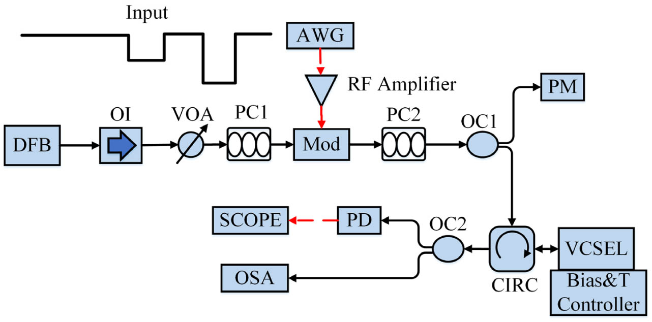
Figure 1.Experimental setup of a VCSEL neuron for reproducing the pyramidal neuron-like dynamics dominated by dCaAPs. AWG, arbitrary waveform generator; DFB, distributed feedback laser; OI, optical isolator; VOA, variable optical attenuator; PC1 and PC2, polarization controllers; Mod, Mach–Zehnder modulator; OC1 and OC2, optical couplers; CIRC, circulator; Bias & T Controller, bias and temperature controller; PD, photodetector; PM, power meter; SCOPE, oscilloscope; OSA, optical spectrum analyzer.
Figure 2(a) presents the polarization-resolved mode powers of the VCSEL as functions of applied bias current with a constant temperature of 18.42°C. We refer to the main lasing mode as the Y-polarized mode (YP mode) and the subsidiary mode as the X-polarized mode (XP mode). It can be seen that the threshold current is about 2.8 mA and there is no polarization switching for all the applied bias currents. The optical spectrum of free-running VCSEL with an applied bias current of 5.4 mA is shown in Fig. 2(b), where the two peaks correspond to the two orthogonal polarization modes (XP and YP modes) of the VCSEL. The wavelengths of the YP and XP modes are with the power of and with the power of . In the experiment, we set the DC biased point of the modulator at 6.5 V. Frequency detuning between the DFB and the XP mode of the VCSEL was . The optical power of the signal injected into the VCSEL was 179.7 μW.
![]()
Figure 2.(a) Polarization-resolved mode powers as functions of applied bias current with a constant temperature of 18.42°C. (b) Optical spectrum of free-running VCSEL with a bias current of 5.4 mA.
B. Theoretical Model
We consider an extension of the well-known spin-flip model (SFM) to reproduce the pyramidal neuron-like dynamics dominated by dCaAPs in a VCSEL [11,12]. The rate equations with optical injection can be described as follows [11,12]:
3. EXPERIMENTAL AND NUMERICAL RESULTS
In this section, we first present the experimental results for emulating the pyramidal neuron-like dynamics dominated by dCaAPs. We then experimentally perform the all-optical XOR classification task based on the reproduced dynamics of the VCSEL neuron. The reproduced dynamics and the all-optical XOR classification task are also demonstrated numerically based on the SFM of the VCSEL neuron. In addition, the effects of duration time and different bias currents on the dynamics of the VCSEL neuron are analyzed carefully.
A. Experimental Results
In Ref. [23], the biological evidence shows that the dendritic electrode evoked somatic spikes with current near threshold but failed to evoke (or evoked less) somatic spikes for higher current intensity by affecting the graded dCaAPs (Fig. 2B(ii) in Ref. [23]). The motivation of this work is to mimic such dynamics in a VCSEL neuron and extend such dynamics to realize high-speed all-optical XOR classification.
Figure 3 presents the mimicking results in a VCSEL neuron under optical injection with three level injected strengths (Level 1, Level 2, and Level 3). We assume that the power of the injected signal decreases from Level 1 to Level 3, as shown in Fig. 3(a). The duration time of each dropped optical injection is set as 10 ns. Figure 3(b) shows the measured results for mimicking the pyramidal neuron-like dynamics dominated by dCaAPs in the VCSEL neuron. We define that a spike is triggered when the power of spikes is larger than the red dashed line. The red dashed line is set according to the spike amplitudes of experimentally measured spiking dynamics in our platform. The amplitude of the red dashed line is set just less than the spike amplitudes. Here, the amplitude of the red dashed line is set as 0.065 V. It can be seen from Fig. 3(b) that in steady state, no spike is generated in the VCSEL which is injection-locked at Level 1 optical injection. In Level 2, the VCSEL goes into the spiking dynamics with a slight over threshold-level optical injection, while in Level 3 the VCSEL changes into the damped oscillations state with transformation from Level 1 to Level 3 (a deeper pulse optical injection). Here, no spike is triggered by Level 3 optical injection. Note that the VCSEL neuron has injection locking, spiking dynamics, and damped oscillations states under Level 1, Level 2, and Level 3 optical injection, respectively. Namely, no spike is generated by a VCSEL neuron without stimuli (Level 1). Furthermore, the optical injection can trigger spikes with threshold-level stimuli (Level 2) and cannot trigger spikes with larger stimuli (Level 3). Hence, the dynamics in the VCSEL neuron under different optical injection is similar to the pyramidal neural dynamics dominated by dCaAPs under different dendritic electrodes as shown in Ref. [23].
![]()
Figure 3.Experimental results for the pyramidal neuron-like dynamics dominated by dCaAPs. (a) Inputs of the VCSEL neuron. (b) Outputs of the VCSEL neuron [also pyramidal neuron-like dynamics dominated by dCaAPs under the optical injection in (a)].
The temporal map of 39 superimposed consecutive outputs from the VCSEL neuron is further presented in Fig. 4. Injection locking, spiking dynamics, and damped oscillations are presented by blue color, yellow color, and red color, respectively. To be seen clearly, the damped oscillations are labeled by the red dashed box in Fig. 4. It can be seen that all 39 consecutive outputs have injection locking, spiking dynamics, and damped oscillations (no-spiking, spiking, and no-spiking states) with Level 1, Level 2, and Level 3 optical injections. The results are similar to Fig. 3. That is to say, the dynamics in the VCSEL neuron is stable and controllable. Hence, we successfully achieved the pyramidal neuron-like dynamics dominated by dCaAPs based on a VCSEL neuron. The dynamics in the VCSEL neuron is hoped to offer a hardware-friendly and highly energy-efficient approach to realize neuromorphic computation.
![]()
Figure 4.Experimental results for the temporal map of superimposed consecutive outputs from VCSEL neuron. Red dashed box labels the damped oscillations of the VCSEL.
B. XOR Classification Task Based on the Dynamics
In this section, we extend the pyramidal neuron-like dynamics dominated by dCaAPs in the VCSEL neuron to perform the XOR classification task. The experimental setup of the VCSEL neuron for performing the all-optical XOR classification task is presented in Fig. 5. Different from Fig. 1, the system has two electronic inputs corresponding to two bits of each case for the XOR classification task. The two electronic inputs from two channels of the AWG are modulated into the optical field by Mod 1 and Mod 2, respectively. As shown in Fig. 5 the two bit sequences are modulated into one optical injection beam. The variable optical delay line is added between the Mod 1 and the Mod 2 to adjust the transmission delay to match the start time of a period for the bits from Mod 1 and Mod 2. PC2 is included to adjust the polarization to match the Mod 2. The optical injection beam containing the information of the two bit sequences is injected into the XP mode of the VCSEL. Other optical paths are the same as Fig. 1. In the experiment, we set the DC biased point of two modulators at 6.5 V and 6.3 V, respectively. Frequency detuning between the DFB and the XP mode of the VCSEL was . The optical power of the injected signal of the VCSEL was 168.6 μW.
![]()
Figure 5.Experimental setup of a VCSEL neuron for XOR classification task based on the dynamics above. Mod1, Mod2, Mach-Zehnder modulators; VODL, variable optical delay line; PC3, polarization controller.
We use the rectangular pulse with the duration time (DT) of 2 ns to represent an input bit of the system. Bit “1” is represented by a dropped pulse and bit “0” is represented by the pulse with the same power of the steady state. We use spiking dynamics to denote the outputs of the optical XOR classification. In the duration time of a bit, a single spike represents bit “1” and no-spike represents bit “0”. Eight two-bit binary cases as shown in Figs. 6(a1) and 6(a2) are generated for the testing of the XOR classification task. The optical inputs of the VCSEL neuron, which are also the accumulated results of two bits in each case, are shown in Fig. 6(a3). It can be seen that three injected levels (Level 1, Level 2, and Level 3) are observed with cases of inputs “00,” “01,” and “10,” as well as “11.” Thus, according to the results of Fig. 3, the experimental results have no-spiking, spiking, and no-spiking states with three stepwise dropped optical injections. It can be seen from Fig. 6(a4) that the “01” and “10” cases can trigger a single spike in the VCSEL neuron. The “00” and “11” cases cannot trigger a spike. Thus, the XOR classification task is achieved successfully in the VCSEL neuron based on the pyramidal neuron-like dynamics dominated by dCaAPs. Note that, we achieved the all-optical XOR classification task with fast time scale (2 ns) and simple hardware. The speed of the XOR classification task is limited by the refractory period of the VCSEL. The refractory period affects the spike rate in the VCSEL. We set a period of single spike generated by the VCSEL as the minimum bit period for the XOR classification task.
![]()
Figure 6.Experimental results of XOR classification tested by eight two-bit binary cases. (a1)–(c2) Eight two-bit binary cases. (a3)–(c3) Inputs of the VCSEL neuron. (a4)–(c4) Outputs of the VCSEL neuron for the results of XOR classification. (a1)–(a4)
Note that it has been shown that the inputs of the excitable system could trigger the asynchronous output spikes [10]. In addition, a larger amplitude pulse may appear at the beginning of the injection-locked state [34]. To tolerate the possible appearance of asynchronous spikes, larger amplitude pulse at the beginning of injection locking, or other unwanted oscillations caused by the unstable experimental environment, we suggest representing the results of the XOR classification task with multiple periodic spikes. To achieve multiple periodic spikes output, we also consider the bit sequences with larger duration time. For instance, the same eight two-bit binary cases with are presented in Figs. 6(b1) and 6(b2). Figure 6(b3) is the inputs of the VCSEL, which is similar to Fig. 6(a3). Here, in the duration time of a bit, two, three or four spikes () represent the bit “1” in the outputs of the XOR classification task and one or no spike represents bit “0.” It can be seen from Fig. 6(b4) that the results of the XOR classification task are also achieved successfully. Similarly, the XOR classification task with the bit duration time of 10 ns also can be achieved in Figs. 6(c1)–6(c4).
C. Numerical Results and Discussions
In this section, the pyramidal neuron-like dynamics dominated by dCaAPs are studied numerically in the VCSEL neuron under different optical injections. The bifurcation diagrams are further presented to identify the dynamics regimes of the VCSEL neuron. Furthermore, the spiking dynamics of the VCSEL under optical injections with different duration times are analyzed carefully. Furthermore, the all-optical XOR classification task is performed based on the SFM of the VCSEL.
Figure 7 presents the inputs and outputs of the VCSEL neuron. The input as shown in Fig. 7(a) is similar to that in the experiment. The duration time is 10 ns for the dropped pulses. We assume that () represents the dropped strength of pulses compared with the constant strength. In this simulation, , 0.075, and 0.15 for Level 1, Level 2, and Level 3, respectively. The frequency detuning between the optical injection signal and the XP mode in the VCSEL is set as . Note that spiking dynamics and oscillations can be observed for the combination of some given parameters including the frequency detuning, optical injection strength, and bias current. In the simulation, the amplitude of the red dashed line is set as 6. With the inputs in Fig. 7(a), the responses of the VCSEL neuron are presented in Fig. 7(b). It can be seen that multiple periodic spikes are generated only with Level 2 optical injection and no spike is generated with Level 1 and Level 3 optical injections. The numerical results agree well with the experimental results. Hence, it is verified that the pyramidal neuron-like dynamics dominated by dCaAPs can be emulated in the VCSEL neuron.
![]()
Figure 7.Simulated results of the pyramidal neuron-like dynamics dominated by dCaAPs in the VCSEL under optical injection. (a) Inputs of the VCSEL neuron. (b) The responses of the VCSEL neuron with the inputs of (a).
The bifurcation diagrams of the maximum as functions of with different bias currents are presented in Fig. 8. It can be seen from Fig. 8 that injection locking (region I), spiking dynamics (region II), and damped oscillations (region III) appear with increasing . In addition, the ranges of spiking dynamics are similar with different currents. More precisely, corresponding to the spiking dynamics are , , and for currents , 2.5, and 2.6, respectively. The dynamics of the VCSEL neuron with optical injection is hoped to get no-spiking and spiking states easily.
![]()
Figure 8.Bifurcation diagrams of the maximum
Figure 9 presents the spiking dynamics of the VCSEL under the dropped pulses with , 6 ns, 3 ns, 2 ns, 1.5 ns, 1 ns, 0.8 ns, and 0.55 ns. It can be seen from Fig. 9(b), for , an asynchronous spike is generated [10], likely as a result of transition between spiking dynamics and injection-locked state [34]. For and , a single spike is generated within the bit duration. While for , multiple periodic spikes can be observed. As mentioned above, we suggest using the multiple periodic spikes to represent the XOR results. But if we would like to increase the processing rate of the XOR task, a lower bit width may be desired. Hence, the trade-off between the accuracy and the operation speed of the proposed XOR operator should be considered for the practical application.
![]()
Figure 9.Spiking dynamics of VCSEL under the dropped pulses with different duration times. (a) Inputs of the VCSEL. (b) Outputs of the VCSEL under the inputs of (a).
Here, for the XOR classification task, the term in Eq. (1) can be written as corresponding to two bits of each case. Ten cases for testing the XOR classification are presented in Figs. 10(a1) and 10(a2). For the steady state and bit “0,” . For the bit “1,” . The duration time of one bit is set as . The frequency detuning between the optical injection signal and the XP mode of the VCSEL is also set as . As can be seen from Fig. 10(a3), spikes are generated with the cases of “10” and “10.” And no spike is observed with the cases of “00” and “11.” Namely, we numerically achieved the XOR classification task in a single VCSEL neuron equipped with the pyramidal neuron-like dynamics dominated by dCaAPs. To tolerate the possible appearance of asynchronous spikes [labeled by a red circle in Fig. 10(b3)], larger amplitude pulse at the beginning of injection-locked state [labeled by a green circuit in Fig. 10(b3)], or other unwanted oscillation caused by the unstable environment, we also use multiple periodic spikes to present the bit “1” in the results of the XOR classification task. One or no spike represents the bit “0” in the results of the XOR classification task. In this way, the XOR classification tasks with the bit duration times of 3 ns and 6 ns are achieved successfully in Figs. 10(b1)–10(b3) and Figs. 10(c1)–10(c3).
![]()
Figure 10.All-optical XOR classification tested numerically by 10 two-bit binary cases. (a1)–(c2) 10 two-bit binary cases. (a3)–(c3) The outputs of the VCSEL neuron for the results of XOR operation. (a1)–(a3)
4. CONCLUSION
In this work, we experimentally and numerically demonstrated an approach to mimic the pyramidal neuron-like dynamics dominated by dCaAPs based on a VCSEL. The mechanisms involved mainly include the injection-locking, spiking dynamics, and damped oscillations in a VCSEL under optical injections with different strengths. Based on these reproduced dynamics, the XOR classification task was achieved experimentally and numerically with a faster time scale (or high accuracy) and simple hardware. The dynamics reproduced in this work, using a single 1550 nm VCSEL, is valuable and offers a novel optical solution to neuromorphic computation with a faster time scale (or high accuracy) and simple hardware. This opens the exciting prospects for information processing and neuromorphic computation traditionally using the multilayer spiking neural network. Furthermore, the photonic spiking XOR classification based on the mimicked dynamics offers fast-speed (or high accuracy) and energy-efficient advantages in information processing, which holds promise for the application in large and complicated photonic spiking neural networks.
References
[1] P. R. Prucnal, B. J. Shastri, T. F. de Lima, M. A. Nahmias, A. N. Tait. Recent progress in semiconductor excitable lasers for photonic spike processing. Adv. Opt. Photonics, 8, 228-299(2016).
[2] T. F. de Lima, H.-T. Peng, A. N. Tait, M. A. Nahmias, H. B. Miller, B. J. Shastri, P. R. Prucnal. Machine learning with neuromorphic photonics. J. Lightwave Technol., 37, 1515-1534(2019).
[3] S. Xiang, Y. Zhang, J. Gong, X. Guo, L. Lin, Y. Hao. STDP-based unsupervised spike pattern learning in a photonic spiking neural network with VCSELs and VCSOAs. IEEE J. Sel. Top. Quantum Electron., 25, 1700109(2019).
[4] X. X. Guo, S. Y. Xiang, Y. H. Zhang, L. Lin, A. J. Wen, Y. Hao. Polarization multiplexing reservoir computing based on a VCSEL with polarized optical feedback. IEEE J. Sel. Top. Quantum Electron., 26, 1700109(2019).
[5] J. Robertson, E. Wade, Y. Kopp, J. Bueno, A. Hurtado. Toward neuromorphic photonic networks of ultrafast spiking laser neurons. IEEE J. Sel. Top. Quantum Electron., 26, 2931215(2020).
[6] A. Zhao, N. Jiang, S. Liu, Y. Zhang, K. Qiu. Physical layer encryption for WDM optical communication systems using private chaotic phase scrambling. J. Lightwave Technol., 39, 2288-2295(2021).
[7] W. Coomans, L. Gelens, S. Beri, J. Danckaert, G. Van der Sande. Solitary and coupled semiconductor ring lasers as optical spiking neurons. Phys. Rev. E, 84, 036209(2011).
[8] A. Hurtado, K. Schires, I. D. Henning, M. J. Adams. Investigation of vertical cavity surface emitting laser dynamics for neuromorphic photonic systems. Appl. Phys. Lett., 100, 103703(2012).
[9] B. J. Shastri, M. A. Nahmias, A. N. Tait, P. R. Prucnal. Simulations of a graphene excitable laser for spike processing. Opt. Quantum Electron., 46, 1353-1358(2014).
[10] B. J. Shastri, M. A. Nahmias, A. N. Tait, A. W. Rodriguez, B. Wu, P. R. Prucnal. Spike processing with a graphene excitable laser. Sci. Rep., 6, 19126(2016).
[11] S. Y. Xiang, A. J. Wen, W. Pan. Emulation of spiking response and spiking frequency property in VCSEL-based photonic neuron. IEEE Photonics J., 8, 1504109(2016).
[12] T. Deng, J. Robertson, A. Hurtado. Controlled propagation of spiking dynamics in vertical-cavity surface-emitting lasers: towards neuromorphic photonic networks. IEEE J. Sel. Top. Quantum Electron., 23, 1800408(2017).
[13] A. Dolcemascolo, B. Garbin, B. Peyce, R. Veltz, S. Barland. Resonator neuron and triggering multipulse excitability in laser with injected signal. Phys. Rev. E, 98, 062211(2018).
[14] M. P. Fok, Y. Tian, D. Rosenbluth, P. R. Prucnal. Pulse lead/lag timing detection for adaptive feedback and control based on optical spike-timing-dependent plasticity. Opt. Lett., 38, 419-421(2013).
[15] R. Toole, M. P. Fok. Photonic implementation of a neuronal algorithm applicable towards angle of arrival detection and localization. Opt. Express, 23, 16133-16141(2015).
[16] Q. Ren, Y. Zhang, R. Wang, J. Zhao. Optical spike-timing-dependent plasticity with weight-dependent learning window and reward modulation. Opt. Express, 23, 25247-25258(2015).
[17] S. Xiang, J. Gong, Y. Zhang, X. Guo, Y. Han, A. Wen, Y. Hao. Numerical implementation of wavelength-dependent photonic spike timing dependent plasticity based on VCSOA. IEEE J. Quantum Electron., 54, 8100107(2018).
[18] A. N. Tait, T. F. de Lima, E. Zhou, A. X. Wu, M. A. Nahmias, B. J. Shastri, P. R. Prucnal. Neuromorphic photonic networks using silicon photonic weight banks. Sci. Rep., 7, 7430(2017).
[19] J. Robertson, T. Deng, J. Javaloyes, A. Hurtado. Controlled inhibition of spiking dynamics in VCSELs for neuromorphic photonics: theory and experiments. Opt. Lett., 42, 1560-1563(2017).
[20] Y. Zhang, S. Xiang, X. Guo, A. Wen, Y. Hao. All-optical inhibitory dynamics in photonic neuron based on polarization mode competition in a VCSEL with an embedded saturable absorber. Opt. Lett., 44, 1548-1551(2019).
[21] J. Feldmann, N. Youngblood, C. D. Wright, H. Bhaskaran, W. H. P. Pernice. All-optical spiking neurosynaptic networks with self-learning capabilities. Nature, 569, 208-214(2019).
[23] A. Gldon, T. A. Zolnik, P. Fidzinski, F. Bolduan, A. Papoutsi, P. Poirazi, M. Holtkamp, I. Vida, M. E. Larkum. Dendritic action potentials and computation in human layer 2/3 cortical neurons. Science, 367, 83-87(2020).
[24] S. M. Bohte, J. N. Kok, H. La Poutre. Error-backpropagation in temporally encoded networks of spiking neurons. Neurocomputing, 48, 17-37(2002).
[25] I. Sporea, A. Grüning. Supervised learning in multilayer spiking neural networks. Neural Comput., 25, 473-509(2013).
[26] R. Hasan, T. M. Taha, C. Yakopcic. On-chip training of memristor crossbar based multi-layer neural networks. Microelectron. J., 66, 31-40(2017).
[27] H. T. Peng, G. Angelatos, T. F. de Lima, M. A. Nahmias, A. N. Tait, S. Abbaslou, B. J. Shastri, P. R. Prucnal. Temporal information processing with an integrated laser neuron. IEEE J. Sel. Top. Quantum Electron., 26, 5100209(2020).
[28] S. Xiang, Z. Ren, Y. Zhang, Z. Song, X. Guo, G. Han, Y. Hao. Training a multi-layer photonic spiking neural network with modified supervised learning algorithm based on photonic STDP. IEEE J. Sel. Top. Quantum Electron., 27, 7500109(2020).
[29] S. Xiang, Z. Ren, Y. Zhang, Z. Song, Y. Hao. All-optical neuromorphic XOR operation with inhibitory dynamics of a single photonic spiking neuron based on a VCSEL-SA. Opt. Lett., 45, 1104-1107(2020).
[30] K. Iga, H. E. Li. Vertical-cavity Surface-emitting Laser Devices(2003).
[31] R. Michalzik. VCSELs: Fundamentals, Technology and Applications of Vertical-cavity Surface-emitting Lasers, 166(2013).
[32] R. Al-Seyab, K. Schires, N. A. Khan, A. Hurtado, I. D. Henning, M. J. Adams. Dynamics of polarized optical injection in 1550-nm VCSELs: theory and experiments. IEEE J. Sel. Top. Quantum Electron., 17, 1242-1249(2011).
[33] J. P. Toomey, C. Nichkawde, D. M. Kane, K. Schires, I. D. Henning, A. Hurtado, M. J. Adams. Stability of the nonlinear dynamics of an optically injected VCSEL. Opt. Express, 20, 10256-10270(2012).
[34] A. Quirce, J. R. Cuesta, A. Hurtado, K. Schires, A. Valle, L. Pesquera, I. D. Henning, M. J. Adams. Dynamic characteristics of an all-optical inverter based on polarization switching in long-wavelength VCSELs. IEEE J. Quantum Electron., 48, 588-595(2012).

Set citation alerts for the article
Please enter your email address
© Copyright 2018-2021 | Chinese Laser Press. All Rights Reserved 沪ICP备15018463号-20