
Chao-Ni Zhang, Hang Li, Jian-Peng Dou, Feng Lu, Hong-Zhe Yang, Xiao-Ling Pang, Xian-Min Jin. Hong–Ou–Mandel interference linking independent room-temperature quantum memories[J]. Photonics Research, 2022, 10(10): 2388
- Photonics Research
- Vol. 10, Issue 10, 2388 (2022)
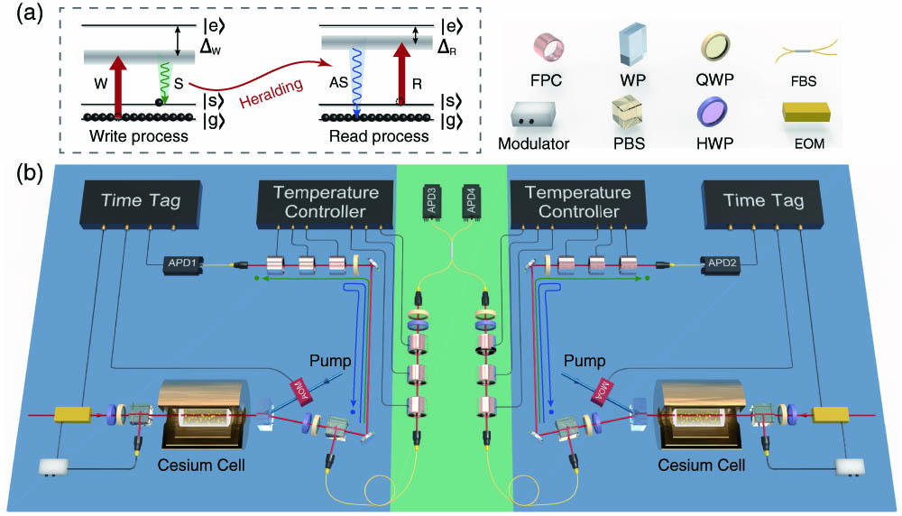
Fig. 1. Schematic view of the experiment. (a) The atomic energy level of Cs 133 | g ⟩ = | 6 S 1 / 2 , F = 3 ⟩ | s ⟩ = | 6 S 1 / 2 , F = 4 ⟩ | e ⟩ 6 P 3 / 2
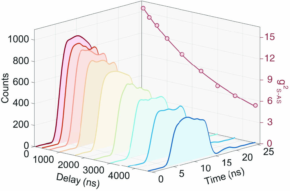
Fig. 2. Heralded single photon with a different time delay in quantum memory. The solid curves in the main part refer to the temporal shape of the generated single photon with a different time delay for retrieval, without reduction of any background noise. The red dots on the right side denote the corresponding cross-correlation function between the Stokes and anti-Stokes photons.
Fig. 3. Characterization of the two single-photon sources from independent room-temperature quantum memories. (a) The counts of the heralded anti-Stokes photons as a function of the write pulse power with 566,037,735 trials performed. The red pentagon refers to the chosen pulse energy in this experiment. (b) The temporal shape of the heralded anti-Stokes photons generated by two photon sources. The blue squares (purple rhombuses) mark the heralded anti-Stokes photons from one photon source detected by APD3 (APD4), while the red dots (orange triangles) represent the heralded anti-Stokes photons that are generated by another photon source and detected by APD3 (APD4). These data are obtained with a pulse energy of 330 pJ and 566,037,735 repeated trials.
Fig. 4. Four-fold coincidence as a function of the time delay between two photons from independent room-temperature quantum memories. The blue dots correspond to the experimental data with an effective measurement of 11,886,792,452 trials, and the solid line represents the theoretical curve. The error bars denote one standard deviation.

Set citation alerts for the article
Please enter your email address
© Copyright 2018-2021 | Chinese Laser Press. All Rights Reserved 沪ICP备15018463号-20