
Pierre Didier, Hamza Dely, Thomas Bonazzi, Olivier Spitz, Elie Awwad, Étienne Rodriguez, Angela Vasanelli, Carlo Sirtori, Frédéric Grillot. High-capacity free-space optical link in the midinfrared thermal atmospheric windows using unipolar quantum devices[J]. Advanced Photonics, 2022, 4(5): 056004
- Advanced Photonics
- Vol. 4, Issue 5, 056004 (2022)
Abstract
Keywords
1 Introduction
Since its adoption in the early 2000s, broadband communication has revolutionized our habits of learning, entertaining, and communicating, owing to continuous improvement in data-transfer speed. In some geographical areas, high-speed internet access is still hindered due to infrastructure issues: wired network expansion implies heavy civil engineering and very high costs. In the meantime, the development of novel midinfrared (MIR) sources like supercontinuum generation,1 optical parametric oscillators (OPOs),2 or cascade laser technology to replace bulky 3 and lead-salt lasers4 has opened up promising prospects in fields such as spectroscopy,5 medicine,6 and free-space optics (FSO) communication. For the latter, wavelengths in the 8 to transparency window of the atmosphere are more resistant to degraded atmospheric conditions,7 including turbulence,8 than their mid- (3 to ) and short-wave infrared counterparts. Semiconductor lasers in this range of the optical spectrum emerged with the realization of quantum cascade lasers (QCLs) in 1994,9 which is now a technology mature enough for applications requiring reliable, powerful MIR sources at room temperature. QCL is a unipolar quantum device based on intersubband transitions with electrons relaxing within a few picoseconds to their ground state.10 This peculiarity should lead to electrical bandwidths of dozens of GHz11 but, practically, local attenuation can worsen the frequency response of QCLs.12 Direct modulation of these semiconductor lasers is thus lagging behind, with a 3-dB bandwidth in the range of 10 GHz for a configuration with an RF-launcher13
In this article, we take the promising results recently obtained36 with midinfrared Stark-effect37 modulators one step further by extending the transmission range to 31 m with a Herriott cell. The high-power signal at the output of the modulator advocates for even longer distances of propagation that would require outside facilities and telescopes for beam shaping.38 In addition, conventional signal pre- and post-processing is implemented in order to achieve a record transmission at a gross rate of with 7% forward-error correction (FEC) overhead using OOK and with 27% FEC using OOK and PAM-4 modulation schemes over 31 m, paving the way toward large-scale adoption in telecom applications. The main advantage of our method is that it can address any midinfrared wavelength and is not restricted by wavelength up- and downconversion, which remains a promising technique for communication below .39 In fact, these techniques benefit from the maturity of the devices at in terms of bandwidth, power, and spectral purity to generate a transmitted midinfrared signal. However, the efficiency is still very low (order of mW) and bulky while power-consuming near-infrared pumps (order of multi-W) are needed.40 Overall, this work shows the relevance of intersubband technology as a key building block of the midinfrared transmission (optical source, external modulator, and detector) and holds much promise as the size-reduction of the modulator is expected to drastically increase the maximum bandwidth, which is a trend already observed in intersubband detectors.41
2 Optical Setup
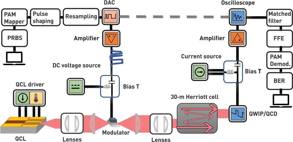
Our free-space communication setup is represented in Fig. 1. The optical source is a commercial wavelength continuous wave (CW) QCL working at room temperature and emitting up to 97 mW of output power at room temperature. The beam emitted by the QCL is expanded with one telescope and focused using another telescope on a external modulator [Fig. 2(a)]. The modulator is bonded to a custom coplanar waveguide and connected to a bias-tee with a 2.92-mm connector. DC bias is provided by an Agilent 33500B generator while the RF signal comes from a Socionext arbitrary waveform generator (AWG) that can provide , with an analog 3-dB bandwidth of 30 GHz. The signal is amplified twice (differential 10 dB D837C and 25 dB 826H SHF amplifiers) to achieve 15-V peak-to-peak voltage required to drive the modulator. Such a high voltage is due to the strong impedance mismatch between the amplifier and the modulator. Tackling this issue to reduce the amplitude of the modulating signal would require a thorough characterization and optimization of the electrical circuit of the modulator to reduce parasitic capacitance and inductance. Two-thirds of the optical power is lost because of reflections on the modulator facets. The modulated midinfrared beam is either directly collected by a MIR high-speed detector or deviated through a 31-m Herriott cell before impinging on the detector. The received signal is acquired with a 33-GHz bandwidth high-speed oscilloscope (Tektronix DPO70000SX) and then processed off-line with Python and MATLAB scripts. Two detectors are used in this work: a passive, room-temperature QCD already presented in one of our previous works,36 and a nitrogen-cooled , mesa QWIP at 77 K with technology inspired by Ref. 17, showing in our case a bandwidth higher than 25 GHz, as shown in Fig. 2(c).
Sign up for Advanced Photonics TOC. Get the latest issue of Advanced Photonics delivered right to you!Sign up now
![]()
Figure 1.Schematic of the full setup. A
![]()
Figure 2.(a) Picture of the connectorized external modulator on its mount with a coplanar waveguide. (b) Modulation depth estimated while measuring the signal voltage on the QCD when voltage pulses are applied on the modulator (blue dots). The measurements are well fitted with a Beer–Lambert law (solid curve). (c) QWIP biased at 4 V and showing a bandwidth >
The Stark-effect-based external modulator is a mesa designed for high-speed operation with quantum engineering preventing charge displacement in the heterostructure, thus avoiding speed throttling due to electronic transport. The 9-GHz bandwidth under RF probing (as depicted by the blue curve in Fig. 3) is mainly limited by its geometric capacitance. Bandwidth may be improved by reducing even further the size of the modulator at the cost of a more challenging optical alignment. To estimate its modulation depth, the modulator is excited with a few microsecond-long voltage pulses between 0 V and peak values ranging from to 9 V. The measurement procedure is detailed in Fig. S1 in the Supplementary Material. Figure 2(b) presents the peak voltage measured on the QCD (proportional to the peak intensity) for various pulse peak voltages applied to the modulator and a Beer–Lambert law fit,
![]()
Figure 3.Bandwidth measurements. Optical response of the full system (modulator, QWIP, and amplifiers) measured using a VNA and injecting a 5 dBm signal in the modulator (green curve). In blue, the rectified current from the modulator when injecting a 0 dBm input signal. The gray curve represents the noise obtained in the same configuration while the midinfrared beam is blocked.
To get an overview of the capabilities of the system, several bandwidth metrics are measured (Fig. 3). First, we measure the electrical bandwidth of the modulator (blue curve) using electrical rectification, and that bandwidth is found to be 9 GHz. This technique consists in measuring the DC current generated by the nonlinear current-voltage characteristic under sinusoidal excitation.43 Then, we use a vector network analyzer (VNA) in order to characterize the frequency response of the full system (modulator, QWIP, and amplifiers) by injecting a 5 dBm electrical signal. This results in the green curve of Fig. 3, while the gray one gives the electrical noise of the exact same system when blocking the beam. Despite a high-level noise above 13 GHz, the signal-to-noise ratio in the 0.1- to 10-GHz range is above 40 dB. The QCL is driven 1.5 times above its threshold current (280 mA). Since the relative intensity noise (RIN) decreases with bias current,44 we assume that the RIN is negligible compared to electrical noise coming from the amplifiers. Compared with our previous setup,36 using a smaller modulator improves the bandwidth by a factor of two and allows for reaching 3-dB bandwidth of 4.5 GHz.
3 Data Transmission Using External Modulator
In this experiment, on–off keying (OOK) and four-level pulse amplitude modulation (PAM-4) are used to transmit data using pseudorandom binary sequences (PRBSs), which are either - or -bit-long patterns. We bias the modulator at a DC value of 1.1 V to work in its linear regime and to reduce distortion as much as possible. We perform measurements for back-to-back (B2B) transmission (i.e., roughly 2-m propagation), and for 31-m propagation transmission using a commercial Herriott cell (Thorlabs HC30L/M-M02) that is inserted in the path of the midinfrared beam. This cell is a two-mirror cavity with a small shifted aperture on each of the mirrors to make the beam bounce back and forth 80 times before exiting. This process adds extra optical losses in the system, but this is limited to 3 dB in our case because the mirrors have a specific coating allowing for a reflectivity higher than 99% at the wavelength of interest. An extra telescope is needed right before the multipass cell to shape the beam and ensure good beam quality at the output of the cell. The transmitted signal is collected by either the QCD or the QWIP detector. In order to evaluate the quality of the transmission, we derive the ratio between the errors in the received data and the total number of bits sent, commonly referred as the bit error rate (BER). The BER is evaluated for the entire acquired sequences that contain ten million samples sampled at . If the BER is below a given threshold, error-correction algorithms can be implemented to correct any remaining errors. Here, we assume that a forward error correction (FEC) code is used to correct the erroneous bits and subsequently leads to an error-free transmission (i.e., orders of magnitude lower BER than presented here) after FEC decoding. However, FEC implies a rate reduction due to the introduction of redundancy bits in data frames. For a maximum pre-FEC BER of 4%, an FEC code leads to a 27% bit overhead and hard-decision (HD) decoding is assumed to be used to achieve an error-free communication, whereas a maximum pre-FEC BER of 0.38% only requires 7% overhead.45 In our case, the optimal results in terms of data rate are obtained for 27% HD-FEC, but a larger overhead introduces more latency because it requires a more complex decoding. For every experiment, we present the gross data rates in the text and the corresponding net bit rates in Table 1 after subtracting the FEC (7% or 27%) and the pilot sequences (5%) overheads. In the following, we will present the eye diagrams of the received signals in order to evaluate the quality of the transmission for several configurations. An eye diagram is a graphical display where the signal is repetitively overlapped on a time interval corresponding to an integer multiple of the bit time length. This tool allows a qualitative analysis of the transmission performance, as an open eye is equivalent to a low error rate.
| Net data rates (Gbit/s) | ||||
| QCD | QWIP | |||
| OOK | PAM4 | OOK | PAM4 | |
| Back to back (2 m) | 21 & | 9 & | 26 & | 21 & |
| Herriott cell (31 m) | 12.5 & | — | 26 & | 21 & |
Table 1. Summary of results in terms of net data rates by taking into consideration overhead of the FEC (HD-FEC 7% and 27%) and the pilot sequence (5%) for equalized signal.
| Attenuation (dB/km) | |||
| Visibility (km) | 1550 nm | 4000 nm | 9000 nm |
| 20 (Clear) | 0.2 | 0.06 | 0.02 |
| 5 (Haze) | 1.2 | 0.47 | 0.2 |
| 2 (Mist) | 4 | 2 | 1.1 |
| 1 (Fog) | 9.3 | 5.4 | 3.3 |
Table 2. Beam attenuation caused by the Mie scattering inspired by the table of Trichili et al.48
We first show the results in B2B in Fig. 4(a). We achieve a rate of without any further processing and with a BER of 0.38% using a cooled QWIP. However, with the QCD receiver, we were only able to reach a BER of 4% at because of the noisy environment added by the amplifier, the modulator, and the laser source. Later, we perform a transmission experiment over a distance of 31 m by using the Herriott cell. With the QWIP receiver, we are able to transmit at with a BER of 3.7% without further digital processing. With the QCD receiver, the lower responsivity and narrower 3-dB bandwidth (around 4.5 GHz) were detrimental for the transmission; consequently, we did not achieve a transmission with a BER below 4%. Indeed, the electrical signal at the output of the QCD is low (around peak-to-peak) leading to the use of a high-gain 40-dB amplifier, which adds extra distortion and affects the quality of the transmission.
![]()
Figure 4.Eye diagrams of transmission without processing for two different data rates using a QWIP. The figure shows the normalized voltage as a function of time: (a)
3.1 Feed-Forward Equalization
Digital equalization is a key step in order to improve dramatically the maximum data rates by compensating the systematic distortions of the channel and minimizing intersymbol interference.46 We apply a fractional-spaced feed-forward equalization (FFE) scheme on the received signal sampled at a rate of four samples per symbol to equalize the received signal. We first learn the coefficients of the FFE filter using a gradient descent (steepest descent) algorithm with a convergence parameter that controls the speed and the accuracy of the learning step. Then, we equalize the received signal using the learned filter for which we define the number of coefficients as . The two parameters, and , are evaluated to optimize the efficiency of the quality transmission. We keep the value below 400 samples (or equivalently 100 symbols) in order to keep a low latency. A smaller value of allows for a more accurate, albeit slower, estimation of the channel distortions while a higher value allows for a fast, however less accurate, estimation. Figure 5 demonstrates the effect of FFE on a B2B transmission performed with the QWIP. The BER without equalization is as high as 7%, so it is impossible to recover error-free data without equalization. By using an FFE with and , the BER drops from 7% to 0.1%, making the transmission error-free when taking into account a subsequent 7% HD-FEC overhead. We are able to reach with a bit-long PRBS for a B2B transmission with 27% HD-FEC overhead. This bit rate is even pushed to in the case of a bit-long PRBS and 27% HD-FEC overhead. In Fig. 5(b), one can see that the transmission quality is much improved by the implementation of equalization. With the QCD transmission, the maximum data rate is for a and a sequence length of as shown in Fig. 5(c).
![]()
Figure 5.Comparison of the two eye diagrams (a) without and (b) with FFE equalization (
3.2 31-m Transmission Using Herriott Cell
We now examine the feasibility of a high-quality transmission over a few dozen of meters. A transmission using OOK with a sequence length of through the Herriott cell has been achieved with a QWIP, as plotted in Fig. 6. The red dots of Fig. 6(d) show the BER before equalization, while the blue ones are the BER after equalization, demonstrating an enhancement by more than one order of magnitude up to . When the same experiment was conducted with the QCD for a -bit long sequence, the maximum data rate we could achieve was at as shown in Fig. 6(a), limited by electrical noise coming from the high-gain amplifiers already mentioned.
![]()
Figure 6.Eye diagrams of the transmission through a 31-m Herriott cell for three different data rates and a sequence length of
3.3 Four-Level Transmission (PAM-4)
To further increase the bit rate using the same symbol rates, switching to higher-order modulation formats, such as PAM-4, is relevant. Further, in some scenarios below, we apply a digital pulse shaping root-raised-cosine (RRC) filter in order to reduce the spectral occupation of the transmitted signal. In these cases, the occupied bandwidth around the optical carrier is where is the roll-off factor of the filter and is the symbol rate. If is close to 1, the bandwidth occupancy is maximum, typically twice the value of the symbol rate. Reducing allows limiting the bandwidth occupancy. By applying pulse shaping with at the transmitter side and FFE equalization at the receiver side, we are able to reach with a -bit long PRBS and a resulting BER of 3.6% in the B2B configuration. An error-free transmission is impossible to achieve in the same conditions without pulse shaping nor FFE equalization. This result probably overestimates the capacity of our link because of the reduced sequence length. More realistically, we achieve with a bit-long sequence and a resulting BER of , both in the B2B configuration and in the 31-m link, as shown in Fig. 7.
![]()
Figure 7.(a) Eye diagram of a B2B equalized
4 Link Budget for Free-Space Transmission
During its propagation, the beam suffers from degradation due to the interaction with the medium, which is in our case the atmosphere. It may come from absorption by gas molecules like carbon dioxide, scattering, or wavefront deformation induced by turbulence. Neglecting wandering and the effect of turbulence in a first approach, losses caused by the propagation of our Gaussian laser beam at can be written as47,48
5 Conclusion
We demonstrated a 31-m long high bitrate data transmission in the to thermal atmospheric window at a gross rate of , with a BER below 0.4% related to 7% HD-FEC using a full set of intersubband quantum devices. This feat was made possible by pre- and post-processing algorithms. For some cases, we shaped the PAM-4 signal with an RRC routine before injecting it into the modulator. In addition, the received signal detected by our high-speed QWIP was equalized by a feed-forward equalization algorithm. Full room-temperature link up to with a BER below 0.4% and 7% HD-FEC was also demonstrated with the exact same distance on our QCD, limited by its low responsivity and high electronic amplifier noise. For a shorter distance transmission (i.e., B2B configuration), we achieved gross rates of with the QWIP and with the QCD, corresponding to a BER below 0.4% and 7% HD-FEC. This work is a key step toward the realization of a real-field midinfrared FSO system as it is, to the best of our knowledge, the first high throughput transmission setup on such a distance in this wavelength domain. In order to create a long-haul FSO link in the midinfrared, we need to build an adaptive optics system to account for other phenomena that can degrade the transmission. This platform has to be able to compensate for the effects of turbulence on the wavefront,49 to avoid pointing errors, and to maximize the received power. Also, our room-temperature detectors are not good enough to target either larger link capacity or range. Nonetheless, this bottleneck can be easily overcome using an actual state-of-the-art MIR detector and yield far better bitrates at room temperature. Furthermore, the beam-shaping method used here for long-range transmission is straightforward and limited to our use-case with the multipass cell. It can be improved with cutting-edge adaptive optics techniques. Likewise, the link capacity could be increased by improving the electronic design on several aspects such as proper impedance matching networks to avoid detrimental frequency behaviors with the amplifiers. A new generation of faster patch antenna-based modulators with reduced capacitance would also bring substantial enhancements with a system bandwidth beyond 50 GHz. Considering ongoing efforts to design fully integrated systems made of intersubband devices, unipolar quantum optoelectronics could bring fast, reliable, and easy-to-deploy optical MIR links within reach in the coming years and be coupled with the recent findings about quantum cascade laser photonic chaos50 to lead to private communication systems resistant to adverse weather conditions.
6 Appendix
At this wavelength, the major cause of diffusion is the Mie and the geometric scattering. Mie’s theory describes elastic scattering light in the direction of propagation caused by particles with a similar or larger diameter than the wavelength. It is mainly caused by fog and haze. We have , according to the empirical Kim model,47,51
The signal endures attenuation due to the presence of large particles like snow, rain, or fog. This is geometric scattering. We describe the different values caused by geometric scattering .52
Pierre Didier received his dual MSc degrees in engineering from Grenoble INP-Phelma, Grenoble, France, and in photonics from Université Grenoble Alpes, Grenoble. He is currently working toward a PhD with Prof. Grillot’s group at Télécom Paris, Palaiseau, France, with a focus on deploying free-space chaotic cryptography systems based on quantum cascade lasers and detectors. He was a research intern with Kungliga Tekniska Högskolan, Stockholm, Sweden, where he worked on X-ray photon detection using single photon semiconductor detectors. He then was with Thales Research Laboratory, Palaiseau, France, working on midinfrared fiber lasers. His research interests include midinfrared photonics, semiconductor components, and communication systems.
Thomas Bonazzi received his MSc degrees in engineering from ESPCI, France and in fundamental physics and condensed matter from ENS, France, and is now working toward a PhD at LPENS in Prof. Sirtori’s group with Prof. Vasanelli, working on high-speed mid-infrared optoelectronic devices with III-V semiconductors and focusing on the development of detectors and modulators for free space optical transmissions.
Olivier Spitz received his PhD in electrical engineering from Université Paris-Saclay, Saclay, France, in 2019, and was awarded the Springer-Nature outstanding thesis prize as well as the Délégation Générale de l’Armement (DGA) thesis prize for his work on the nonlinear dynamics of quantum cascade lasers under external optical feedback/injection. His work on private communication with chaotic quantum cascade lasers was one of the 30 featured discoveries in the 2021 OPN’s Year in Optics. He is now a postdoctoral researcher at the University of Central Florida, Orlando, Florida.
Elie Awwad joined Télécom Paris in October 2019 as an assistant professor (Maître de Conférences) in the optical transmission team. His current research deals with mitigation of nonlinear effects in fiber optic communications, margin reductions in optical networks, and optical fiber sensing. He holds a PhD in communications and electronics from Télécom Paris (2015). He worked as a research scientist at Nokia (formerly Alcatel-Lucent) Bell Labs from 2015 until 2019.
Carlo Sirtori received his PhD in physics from the University of Milan in 1990. The same year he joined Bell Labs, where he started his research career in quantum devices. At Bell Labs, he was one of the inventors of the Quantum Cascade Laser. In 1997, he joined THALES Research & Technology (TRT) in France and soon after became the head of the Semiconductor Laser Group. He was appointed full professor at the University of Paris Diderot in 2003 and in 2018 moved to the École Normale Supérieure as professor/chair at ENS-THALES. He is the author of over 280 articles and has given some 150 invited talks at international conferences. He has received several prestigious awards, such as the Fresnel Prize (European Physical Society) or the “Quantum Devices Award.” In 2010, he was also awarded an ERC Advanced Grant for his pioneering research on light–matter interaction.
Frédéric Grillot is currently a full professor at Télécom Paris (France) and a research professor at the University of New Mexico. His current research interests include, but are not limited to, advanced quantum confined devices using III-V compound semiconductors, quantum dots/dashes, light-emitters based on intersubband transitions, nonclassical light, nonlinear dynamics, and optical chaos in semiconductor laser systems as well as microwave and silicon photonics applications. He strongly contributes to promoting and supporting the development of the general optics community. He has published over 130 journal articles, three book chapters, and many contributions in major international conferences and workshops. He is also a Fellow Member of SPIE, as well as a senior member of the IEEE Photonics Society and of Optica, where he also serves as deputy editor of Optics Express. In 2022, he received the IEEE Photonics Society Distinguished Lecturer Award, which is designed to honor excellent speakers who have made technical, industrial, or entrepreneurial contributions to the field of photonics.
Biographies of the other authors are not available.
References
[9] J. Faist et al. Quantum cascade laser. Science, 264, 553-556(1994).
[28] X. Pang et al. 11 Gb/s LWIR FSO transmission at
[46] J. G. Proakis, M. Salehi. Digital Communications, 4(2001).
[48] A. Trichili et al. Roadmap to free space optics. J. Opt. Soc. Am. B, 37, A184-A201(2020).
[51] H. Kaushal, V. Jain, S. Kar. Free Space Optical Communication(2017).
[52] A. Ghasemi, A. Abedi, F. Ghasemi. Terrestrial Mobile Radio Propagation, 215-287(2012).

Set citation alerts for the article
Please enter your email address
© Copyright 2018-2021 | Chinese Laser Press. All Rights Reserved 沪ICP备15018463号-20