
Qinggang Lin, Xinming Yuan, Xuanke Zeng, Yatao Yang, Yi Cai, Xiaowei Lu, Maijie Zheng, Congying Wang, Wenhua Cao, Shixiang Xu. Single-shot terahertz polarization detection based on terahertz time-domain spectroscopy[J]. Photonics Research, 2022, 10(6): 1374
- Photonics Research
- Vol. 10, Issue 6, 1374 (2022)
Abstract
1. INTRODUCTION
Terahertz (THz) time-domain spectroscopy (THz-TDS) has been widely applied due to its unique ability to simultaneously measure the refractive indices and absorption coefficients of various materials in the THz region [1–3]. However, traditional THz-TDS fails to detect directly polarization information, so it cannot be used to sample directly the polarization-related properties, such as magneto-optical effect [4,5], birefringence and complex permittivity [1,6], chiral molecular identification [7], and polarization imaging [8,9]. Despite this, through traditional THz-TDS, THz polarization information can still be characterized by multiple measurements with different orientations of the THz polarizer or electro-optical (EO) crystal used [1–3,8]. By inducing time delays to cascade the THz-TDS of the THz orthogonal components [10,11], THz-TDS by electro-optical sampling (EOS) with birefringent crystals can carry out the THz polarization detection with a single scan. Some other developments have also been made to detect the THz orthogonal components, simultaneously, e.g., setting two arms for orthogonal detection in THz-TDS by EOS [12,13], adding periodic modulation of the probes through rotating the EO crystals or the polarizers continuously [14–18], as well as adopting special photoconductive antenna detectors with three contacts or four contacts [19–21]. However, all above need pump-probe scans for one or more times, so excellent repetition is required for their targets, and the detections are vulnerable to the disturbances from the fluctuations of the detection systems and environments. In recent years, some methods have been made to realize single-shot THz-TDS [22–24], which can avoid the detections from the time-consuming pump-probe scans and the requirement of repeatability. Unfortunately, all the single-shot setups are not able to work directly well for THz polarization characterization. Consequently, we focus on the design to realize effectively single-shot THz polarization detection (SS-THz-PD) based on THz-TDS by EOS. It can simultaneously detect the horizontal and vertical components of THz-TDS based on THz phase modulations without the need for an optical scan; thus, it can work with high effectivity and high quality.
2. PRINCIPLE AND DESIGN
Our SS-THz-PD orginates from the combination of THz-TDS by EOS with the single-shot Stokes vector detection [25] and spectral interference [23]. As we know, the 45° optical-biased THz-TDS by EOS [26] can record THz polarization characteristics by inserting a half-wave plate (as shown in Fig. 1), where a polarizer (P) is set with its transmission axis along the polarization direction of the probe to purify the probe polarization; then a quarter-wave-plate (QWP) is arranged to change the linear polarization into circular polarization. Suppose the probe intensity with a frequency of is ; after passing through a (110) zinc telluride (ZnTe) crystal with its (001) axis along the vertical direction, the output signal can be expressed as [8]
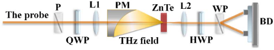
Figure 1.Schematic diagram of 45° optical bias THz-TDS by EOS. P, polarizer; WP, Wollaston polarizer; QWP, quarter-wave plate; HWP, half-wave plate; L1, L2, lenses; PM, off-axis parabolic mirror; ZnTe, (110) ZnTe crystal; BD, balanced detector.
On the other hand, after passing through the ZnTe crystal, the probe field (, ) can be expressed by Jones matrices as
Sign up for Photonics Research TOC. Get the latest issue of Photonics Research delivered right to you!Sign up now
The single-shot Stokes vector detection method [25] was reported, which needs two thick birefringent crystals and a high-resolution spectrometer. From the discussion above, for our THz polarization detection, is unnecessary. In order to extend the method suitably for our SS-THz-PD, we make some improvements on its design, meanwhile combining it with our improved common-path spectral interferometer (ICP-SI) [23]. Figure 2 shows the design of the SS-THz-PD based on THz-TDS. In the setup, the (001) axis of the (110) ZnTe crystal used is along the vertical direction, which is parallel to the principal axis of the polarizer P2. The fast axes of QWP1 and QWP2 are oriented at 45° and 90°, while the optical axis of the birefringent crystal used is along an angle of 45° from the (001) axis, respectively. A pulse stretcher is used to broaden the probe in order to cover temporally the target THz pulses for single-shot detection. This stretcher consists of a pair of 180° folding right-angle SF57 prisms displaced face to face with each other. It folds the optical path inside the prisms and has tunable dispersion by shifting one of the prisms in compact structures [27]. According to this design, we can describe the evolution of the probe field (, ) out of the ZnTe crystal to the spectrometer (, ) with Jones matrices as
![]()
Figure 2.Setup of SS-THz-PD. ST, pulse stretcher; P1, P2, polarizers; QWP1, QWP2, quarter-wave-plates; L1, L2, lenses; PM, off-axis parabolic mirror; ZnTe, (110) ZnTe crystal; α-BBO,
As a result, the recorded signal by the spectrometer can be described with Stokes parameters (, , and ) by
The in Eq. (8) recorded by a spectrometer is shown with a spectral interferogram. Its interference fringes are determined directly by the time delay induced from the α-BBO plate, but also modified by the THz signals. It includes two parts. One, , the DC component does nothing with the target THz field, while the other, the AC component, is responsible for the interference fringes with the polarization-dependent information of the THz field, as well as the birefringent phase difference introduced by the birefringent crystal. Accordingly, the horizontal and vertical component information of the THz field can be extracted by Fourier transform and filter processing from the measured spectral interferogram with THz modulation. In our experiments, in order to avoid the influences from the static birefringent phases, including and those due to the adjustment errors of the birefringent crystal and the QWP, we make two records of the spectral interferograms with and without THz modulation, and then subtract the latter from the former. The phase modulations on the probe by the horizontal [or ] and vertical [or ] components of the target THz field can be extracted by
Of course, the THz temporal signals and can be obtained by using frequency-to-time mapping approximation of the chirped probe pulse, which will result in a resolved time as large as [28], where or is the duration of the transformed-limited probe before or after being chirped. In order for high temporal resolution, we extract and by the following Fourier transforms [22]:
The descriptions above mean that we can extract the THz polarization information by the following steps: 1) record a spectral interferogram without THz modulation, which provides only the DC part, the or , and also the probe spectrum; 2) record another spectral interferogram with THz modulation; 3) extract the AC part by subtracting the former interferogram from the latter to suppress the influences from the static birefringence; 4) apply Fourier transform to the AC part and therefore get two separate temporal components; 5) extract the temporal components by temporal filtering and implement inverse Fourier transform to get and ; 6) on the precalibration of the static birefringence , get and ; thus the modulation phases: and , on the probe by the horizontal and vertical THz fields and , respectively. Finally, get and through the transforms according to Eqs. (12a) and (12b). These steps can be further illustrated with Fig. 3 by simulation. Obviously, we can see that SS-THz-PD can measure the THz polarization state by only recording one spectral interferogram after some precalibrations.
![]()
Figure 3.Illustration of the data process by simulation to extract the horizontal and vertical components of THz temporal waveforms.
3. RESULTS AND DISCUSSION
During our experiments, the laser source used is a 1 kHz-3.5 W-40 fs-800 nm Ti:sapphire amplifier. Most of its output power is used to pump a MgO: crystal to generate the THz field [29]. The rest, a small part of the output, works as the probe. After passing through the pulse stretcher, the probe pulses are broadened to 15.5 ps. A 1-mm-thick (110) ZnTe crystal is used for THz EOS, and a 6-mm-long crystal is chosen to induce a time delay of 2.5 ps between the horizontal and vertical components of the probe. The spectrometer is an HR4000 (Ocean Optics Inc.) with a spectral resolution of 0.1 nm from 720 to 880 nm.
To verify the feasibility of our SS-THz-PD, we set three target polarizations: vertical linear polarization, oriented linear polarization from horizontal direction, and right-handed circular polarization of the THz fields as our targets. Here, the THz fields have been maximized with their vertical linear polarization. linear polarization is gotten with two wire grid polarizers. A 2.7 mm-thick quartz plate with its optical axis parallel to its crystal plane can provide a birefringent phase difference of at 0.28 THz, so is used as an imperfect THz QWP (due to the material dispersion) for a rough conversion from linear to right-circular because of the lack of a broadband THz QWP at hand. Based on the dispersion of quartz crystal in the THz region, we have compared the detected (blue lines) with the calculated (red lines) signals for both the horizontal and vertical components in Fig. 4. We conclude that it can work, but cannot do so exactly. However, the nonuniform absorption of the quartz plate to the different spectral components, and the frequency-dependent diffraction loss induced by the limited aperture of the quartz plate also contribute to the discrepancy between the measured and the calculated THz waveforms.
![]()
Figure 4.Comparison between the measured (blue lines) and the calculated (red lines) signals of the (a) horizontal and (b) vertical components from the THz temporal waveforms with circular polarization converted from the linearly polarized THz signal by using a 2.7 mm quartz plate.
In order to confirm the validity of SS-THz-PD, we compare the measurement results with those measured with the ICP-SI. The arrangement is the same as the SS-THz-PD, except using a half-wave plate, instead of the QWP2 in Fig. 2. By using ICP-SI, we make two separated measurements for the THz horizontal and vertical components to carry out the polarization detection by rotating the half-wave plate with and 22.5°.
Figure 5 shows the THz time-domain signals measured by our SS-THz-PD (red lines) and ICP-SI (blue lines). For three polarization states of the target THz field: vertical linear polarization, oriented linear polarization, and right-handed circular polarization, Figs. 5(a)–5(c) show the measured THz horizontal components, while Figs. 5(d)–5(f) correspond to the THz vertical components. Figure 5(d) also shows its THz spectrum with an insert at its top-left corner, covering from 0.05 to 0.6 THz. During the measurements, the integration time of the spectrometer is set at 50 ms, and the results are the average over about 300 times measurements. From Fig. 5, we can see that there are very excellent consistencies between the detected results by SS-THz-PD and ICP-SI, which verifies the validity of our SS-THz-PD. The little differences between the two measurements may mainly be caused by the adjustment errors of the wave plate and polarizers. For example, to realize THz measurement with different polarizations, the HWP in ICP-SI needs to be set at 0° and 22.5°, respectively. However, 22.5° is difficult to be calibrated accurately. We have simulated the influence of the angle deviation from 22.5°. For example, for the vertical component of the THz signal polarized along , when the deviation is beyond 1°, distortion of the detected signal is obvious. If the deviation reaches 2°, the peak-peak value of the THz pulse changes by more than 15.1%.
![]()
Figure 5.THz temporal signals measured by SS-THz-PD (red lines) and ICP-SI (blue lines) for three target polarizations: vertical linear polarization,
From the horizontal and vertical components of the THz time-domain signals in Fig. 5, we can extract the THz polarization distributions. Figures 6(a)–6(c) are the distributions corresponding to the THz signals with vertical linear, oriented linear, and right-handed circular polarizations, respectively. The extracted THz polarization characteristics agree well with our predictions.
![]()
Figure 6.THz polarization distribution characteristics measured by SS-THz-PD (red line) and ICP-SI (blue line) for the target THz polarization states: (a) vertical polarization, (b) −60° polarization, and (c) right circular polarization.
Like ICP-SI, SS-THz-PD also works with a birefringent plate to modulate terahertz information into the AC component of the recorded spectral interferogram. As stated in Ref. [24], compared with the detections of 45° optical bias THz-TDS by EOS based on polarization-sensitive intensity modulation, those based on common-path spectral interference, e.g., ICP-SI, can get better measurement quality, or higher detection signal-to-noise ratios (SNRs) when operating at single-shot mode. Figure 7 presents the measurement results by using SS-THz-PD (red color) and ICP-SI (blue color). Figures 7(a)–7(c) correspond to the three target THz polarization states of the THz fields, as shown in Figs. 5(a)–5(c). The red or the blue zones gather the 300 measurements of THz temporal signals with SS-THz-PD or ICP-SI. Obviously, these zones can reveal the fluctuations of the measurement results. The black lines (also shown in Fig. 5) are their root mean square (RMS) over the 300 measured waveforms, respectively, so the SNRs are also calculated and presented.
![]()
Figure 7.300 groups of measured THz temporal signals by using SS-THz-PD (red color zones) and ICP-SI (blue color zones) and their RMS averages (black lines in the zones) for three target polarizations: vertical linear polarization,
From Fig. 7, we can see that both the measured signals and the noises by using SS-THz-PD and ICP-SI at comparable levels, thereby having similar SNRs. As described by Eqs. (2) and (3), the detection sensitivity of (110) ZnTe crystal for the horizontally polarized THz pulses is twice that for the vertically polarized, so during our signal processing, the vertically polarized THz signals have been multiplied by a factor of 2 to reflect the real THz amplitudes.
Figure 7 also shows the measurement results of the circular polarization are noisier than the linear polarizations. As stated above, in our setup, the generated THz signal is linearly polarized, and the circular polarization is converted into the linear with a THz QWP; then the two measured orthogonal components are decomposed from the circular polarization. Accordingly, both their amplitudes are smaller than that of the original linear polarization. Additionally, the losses from the THz absorption, the uncoated surface reflections, and the limited aperture of the quartz plate further weaken the measured signals. All above results in the signals are noisier than those with linear polarizations.
Figure 8 tries to make a comparison of the detected SNRs of the THz fields by using SS-THz-PD and the single-shot 45° optical bias THz-TDS by EOS plus spectral encoding [28], which works on polarization-sensitive intensity. Here, we use red for the former, and blue for the latter. Obviously, the SNR of the former is about twice as high as those of the latter. That is to say, our experiments also confirm that the setups on common-path spectral interference can get better SNRs than those on the polarization-sensitive intensity modulation [22].
![]()
Figure 8.300 groups of measured THz temporal signals by using SS-THz-PD (red color zones) and traditional 45° optical bias THz-TDS by EOS (blue color zones) and their RMS averages (black lines in the zones): (a) horizontal components and (b) vertical components.
4. CONCLUSIONS
In summary, we have presented what we believe is a novel design based on THz-TDS by EOS for single-shot THz polarization detection, named SS-THz-PD. It combines THz EOS, single-shot Stokes vector detection, and spectral interference. Its validity has been confirmed by comparing its detection results with those of the reported common-path spectral interferometer through the two separate measurements for two orthogonal components. Our results also show SS-THz-PD has comparable detection SNRs with ICP-SI because both work on spectral interference. However, it is obviously superior to the single-shot 45° optical bias THz-TDS by EOS, which operates on the polarization-sensitive intensity modulation. This setup works without the need for any optical scan, which does not only save time, but also efficiently avoids the disturbances from the fluctuations of the system and environment. Its single-shot mode allows it to work well for the applications with poor or no repeatability. This work provides a powerful tool to do effective and fast THz polarization detection, so it can be applied in many important fields, e.g., THz polarization imaging and material characterization, THz spectroscopy, and the interactions of intense THz fields with materials.
References
[1] T. Nagashima, M. Hangyo. Measurement of complex optical constants of a highly doped Si wafer using terahertz ellipsometry. Appl. Phys. Lett., 79, 3917-3919(2001).
[2] X. Wu, C. Zhou, W. R. Huang, F. Ahr, F. X. Kärtner. Temperature dependent refractive index and absorption coefficient of congruent lithium niobate crystals in the terahertz range. Opt. Express, 23, 29729-29737(2015).
[3] A. Buzády, R. Gálos, G. Makkai, X. Wu, G. Tóth, L. Kovács, G. Almási, J. Hebling, L. Pálfalvi. Temperature-dependent terahertz time-domain spectroscopy study of Mg-doped stoichiometric lithium niobate. Opt. Mater. Express, 10, 998-1006(2020).
[4] R. Shimano, G. Yumoto, J. Y. Yoo, R. Matsunaga, S. Tanabe, H. Hibino, T. Morimoto, H. Aoki. Quantum Faraday and Kerr rotations in graphene. Nat. Commun., 4, 1841(2013).
[5] R. Valdés Aguilar, A. V. Stier, W. Liu, L. S. Bilbro, D. K. George, N. Bansal, L. Wu, J. Cerne, A. G. Markelz, S. Oh, N. P. Armitage. Terahertz response and colossal Kerr rotation from the surface states of the topological insulator Bi2Se3. Phys. Rev. Lett., 108, 087403(2012).
[6] V. C. Agulto, K. Toya, T. N. K. Phan, V. K. Mag-usara, J. Li, M. J. F. Empizo, T. Iwamoto, K. Goto, H. Murakami, Y. Kumagai, N. Sarukura, M. Yoshimura, M. Nakajima. Anisotropic complex refractive index of β-Ga2O3 bulk and epilayer evaluated by terahertz time-domain spectroscopy. Appl. Phys. Lett., 118, 042101(2021).
[7] Z. Zhang, C. Zhong, F. Fan, G. Liu, S. Chang. Terahertz polarization and chirality sensing for amino acid solution based on chiral metasurface sensor. Sens. Actuators B Chem., 330, 129315(2021).
[8] P. C. M. Planken, H.-K. Nienhuys, H. J. Bakker, T. Wenckebach. Measurement and calculation of the orientation dependence of terahertz pulse detection in ZnTe. J. Opt. Soc. Am. B, 18, 313-317(2001).
[9] S. Watanabe. Terahertz polarization imaging and its applications. Photonics, 5, 58(2018).
[10] M. A. Baez-Chonrro, B. Vidal. Single trace terahertz spectroscopic ellipsometry. Opt. Express, 27, 35468-35474(2019).
[11] L. Zhang, H. Zhong, C. Deng, C. Zhang, Y. Zhao. Terahertz wave polarization analyzer using birefringent materials. Opt. Express, 17, 20266-20271(2009).
[12] M. B. Byrne, M. U. Shaukat, J. E. Cunningham, E. H. Linfield, A. G. Davies. Simultaneous measurement of orthogonal components of polarization in a free-space propagating terahertz signal using electro-optic detection. Appl. Phys. Lett., 98, 151104(2011).
[13] F. Sanjuan, G. Gaborit, J. Coutaz. Full electro-optic terahertz time-domain spectrometer for polarimetric studies. Appl. Opt., 57, 6055-6060(2018).
[14] N. Nemoto, T. Higuchi, N. Kanda, K. Konishi, M. Kuwata-Gonokami. Highly precise and accurate terahertz polarization measurements based on electro-optic sampling with polarization modulation of probe pulses. Opt. Express, 22, 17915-17929(2014).
[15] D. J. Aschaffenburg, M. R. C. Williams, C. A. Schmuttenmaer. Terahertz spectroscopic polarimetry of generalized anisotropic media composed of Archimedean spiral arrays: experiments and simulations. J. Chem. Phys., 144, 174705(2016).
[16] Y. Kawada, K. Yoshioka, Y. Arashida, I. Katayama, J. Takeda, H. Takahashi. Simultaneous acquisition of complex transmittance and birefringence with two counter-rotating, circularly polarized THz pulses. Opt. Express, 26, 30420-30434(2018).
[17] K. Suzuki, K. Oguchi, Y. Monnai, M. Okano, S. Watanabe. Spatio-temporal imaging of terahertz electric-field vectors: observation of polarization-dependent knife-edge diffraction. Appl. Phys. Express, 12, 052010(2019).
[18] K. Xu, E. Bayati, K. Oguchi, S. Watanabe, D. P. Winebrenner, M. H. Arbab. Terahertz time-domain polarimetry (THz-TDP) based on the spinning E-O sampling technique: determination of precision and calibration. Opt. Express, 28, 13482-13496(2020).
[19] K. Peng, D. Jevtics, F. Zhang, S. Sterzl, D. A. Damry, M. U. Rothmann, B. Guilhabert, M. J. Strain, H. H. Tan, L. M. Herz, L. Fu, M. D. Dawson, A. Hurtado, C. Jagadish, M. B. Johnston. Three-dimensional cross-nanowire networks recover full terahertz state. Science, 368, 510-513(2020).
[20] D. S. Bulgarevich, M. Watanabe, M. Shiwa, G. Niehues, S. Nishizawa, M. Tani. A polarization-sensitive 4-contact detector for terahertz time-domain spectroscopy. Opt. Express, 22, 10332-10340(2014).
[21] A. Hussain, S. R. Andrews. Ultrabroadband polarization analysis of terahertz pulses. Opt. Express, 16, 7251-7257(2008).
[22] S. Zheng, X. Pan, Y. Cai, Q. Lin, Y. Li, S. Xu, J. Li, D. Fan. Common-path spectral interferometry for single-shot terahertz electro-optics detection. Opt. Lett., 42, 4263-4266(2017).
[23] S. Zheng, Q. Lin, Y. Cai, X. Zeng, Y. Lin, S. Xu, J. Li, D. Fan. Improved common-path spectral interferometer for single-shot terahertz detection. Photon. Res., 6, 177-181(2018).
[24] S. M. Teo, B. K. Ofori-Okai, C. A. Werley, K. A. Nelson. Single-shot THz detection techniques optimized for multi-dimensional THz spectroscopy. Rev. Sci. Instrum., 86, 051301(2015).
[25] K. Oka, T. Kato. Spectroscopic polarimetry with a channeled spectrum. Opt. Lett., 24, 1475-1477(1999).
[26] X. Pan, Y. Cai, X. Zeng, X. Lu, D. Zhang, J. Li, H. Chen, S. Xu. Modified THz electro-optic sampling for high optical modulation depth, large dynamical range and low background noises. Opt. Lett., 39, 3778-3781(2014).
[27] S. Zheng, Y. Cai, X. Pan, X. Zeng, J. Li, Y. Li, T. Zhu, Q. Lin, S. Xu. Two-step phase-shifting SPIDER. Sci. Rep., 6, 33837(2016).
[28] Z. Jiang, X. Zhang. Electro-optic measurement of THz field pulses with a chirped optical beam. Appl. Phys. Lett., 72, 1945-1947(1998).
[29] L. Wang, G. Tóth, J. Hebling, F. Kärtner. Tilted-pulse-front schemes for terahertz generation. Laser Photon. Rev., 14, 2000021(2020).

Set citation alerts for the article
Please enter your email address
© Copyright 2018-2021 | Chinese Laser Press. All Rights Reserved 沪ICP备15018463号-20