Abstract
Airy optical beams have emerged to hold enormous theoretical and experimental research interest due to their outstanding characteristics. Conventional approaches suffer from bulky and costly systems, as well as poor phase discretization. The newly developed metasurface-based Airy beam generators have constraints of polarization dependence or limited generation efficiency. Here, we experimentally demonstrate a polarization-independent silicon dielectric metasurface for generation of high-efficiency Airy optical beams. In our implementation, rather than synchronous manipulation of the amplitude and phase by plasmonic or Huygens’ metasurfaces, we employ and impose a 3/2 phase-only manipulation to the dielectric metasurface, consisting of an array of silicon nanopillars with an optimized transmission efficiency as high as 97%. The resultant Airy optical beams possess extraordinarily large deflection angles and relatively narrow beam widths. Our validated scheme will open up a fascinating doorway to broaden the application scenarios of Airy optical beams on ultracompact photonic platforms.1. INTRODUCTION
Berry and Balazs [1] manifested the Airy wave packet in the context of quantum mechanics, i.e., a nontrivial solution of the Schrödinger equation. In 2007, Siviloglou and Christodoulides conducted the theoretical derivation and experimental verification of an optical version of the Airy wave packet by introducing a finite energy Airy beam [2,3]. The Airy optical beam is a propagation-invariant solution of the paraxial wave equation in one transverse dimension developed in ray optics or catastrophe optics, and it exhibits the following three intriguing characteristics: (i) it is nearly diffraction-free; (ii) the propagation trajectory is parabolically self-accelerating in a way analogous to projectiles moving under the force of gravity; and (iii) it recovers itself while facing an obstacle, i.e., it is self-healing.
The early experimental demonstrations of Airy beams have paved the way for a wide range of applications in the field of material processing [4], light-induced curved plasma channels [5,6], optical manipulation of bioparticles [7], Airy plasmons [8], and high-resolution optical imaging [9–13]. So far, there are diversified schemes to generate Airy beams, for example, using reflective spatial light modulators (SLMs) [14–17], transmissive liquid crystals [18–20], metallic nanostructures [8], dielectric metasurfaces [21], etc. However, SLMs are not capable of producing highly deflected Airy beams. The corresponding phase profiles have large slopes such that the poor phase discretization implemented in SLMs or liquid crystals drastically degrades the quality of the generated beam profiles. In addition, the aforementioned schemes, which are not very cost-effective due to their bulky optical setups, limit the application scenarios of accelerating Airy beams, such as the integration into compact optical and photonic platforms.
Metasurfaces, composed of suitably chosen arrays of subwavelength metal or dielectric optical elements, have gained significant recognition for having the unique ability to flexibly control the phase, polarization, and amplitude of light at the nanoscale with ease [22–34]. They have opened up a fascinating avenue in functional nanophotonics, for example, holography [35–37], light shaping [38–44], achromatic lenses and imaging [45–50], tunable platforms with phase-change materials [51,52], and ultraviolet large bandgap devices [53,54]. Recently, a number of metasurfaces have been demonstrated regarding the generation of Airy beams by synchronous manipulation of the amplitude and phase of incident waves [55–59]. However, the currently available schemes suffer from inevitable low efficiency as very limited design parameters of unit elements can be exploited to cover the full phase range of , and those available choices may happen to have unexpected low transmissions [55,56]. On the other hand, conventional schemes lack the rotational symmetry of the unit elements, which confines the metasurfaces to operate on specific polarization states [56,57,60]. Nevertheless, Huygens’ metasurfaces, which rely on the electric and magnetic resonances of meta-atoms, have the ability to reduce transmission losses and simultaneously cover the full phase. The high-efficiency Airy beam generator based on Huygens’ metasurfaces has been experimentally demonstrated to operate at the gigahertz and terahertz frequencies, but so far, no demonstration has been made in the visible or near-infrared regime [57].
Sign up for Photonics Research TOC. Get the latest issue of Photonics Research delivered right to you!Sign up now
In this paper, to overcome the above-mentioned limitations of conventional schemes, we demonstrate a high-efficiency as well as polarization-insensitive generation of highly deflected Airy beams in the near-infrared regime. We employ a scheme based on the 3/2 phase-only manipulation by spatially varying the diameter of the dielectric cylinder unit element of the metasurface [61], rather than synchronous manipulation of the amplitude and phase. The geometric parameters of the cylinder unit are optimized to realize a phase coverage with ease, with the transmission near unity when the diameter falls in two-thirds of the whole parameter range. A distinguishable envelope of our resultant Airy beam is directly molded without filtration of the polarization states for the input and output beams, which, however, cannot be achieved by Pancharatnam-Berry-based metasurfaces [56,57,60]. The generation efficiency is 56%, which is comparable to the 53%–61% realized by metasurfaces [62], and approximately 3 times that of metallic plasmonic metasurfaces [56]. Different from some pioneers’ work, which already demonstrated polarization-independent high-efficiency metasurfaces [63–69], our paper especially focuses on the application of polarization-independent metasurfaces to the high-efficiency generation of an Airy beam. In addition, the horizontal deflection of the Airy beams is as large as 128 times higher than that produced with conventional SLMs [18] and 56 times higher than that based on the recently reported spin-controlled metasurface [62] under the conditions of the same propagation distance. Meanwhile, the beams retain the full width at half-maximum (FWHM) at an average of as small as 3.5 μm (). The presented scheme will pave the way for widespread applications of Airy beams in ultracompact, highly integrated photonic systems in various ways.
2. THEORETICAL MODEL AND DESIGN
Berry and Balazs [1] proposed a theoretical model for the approximation of Airy beam as , where is a constant and is the propagation direction. Since the amplitude of the Airy function decreases with increasing , Cottrell neglected the amplitude, and presumed that the Airy beam can be generated by phase-only manipulation of the incident beam according to the above function [18]. Here we briefly introduce a derivation of the relationship between the induced phase and the resultant trajectory. As shown in Fig. 1, a field pattern with the trajectory of results from the constructive interference of the refracted light through each pixel of the metasurface. In Fig. 1, two black dashed lines that are tangents at the trajectory at the point and intersect with the points and located on the phase profile line (blue dashed line). The tangent of the trajectory is expressed as . marked at the right side of the vertical axis arrow denotes that the optical path of the point on the blue dashed line is ahead of the point on the metasurface. We will not deduce in detail that the phase profile marked with the blue dashed line is perpendicular to the tangents of the trajectory as the black dashed lines, that is
Equation (1) yields that . Therefore, the 3/2 phase profile along the horizontal axis is
Similarly, a two-dimensional 3/2 phase imposed by the metasurface is defined as the addition of the phases along the and the directions individually based on Eq. (2), where the axis is perpendicular to the – plane.
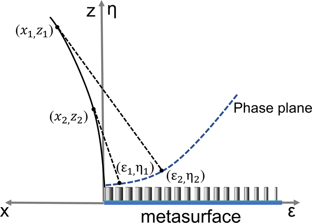
Figure 1.Geometrical model for generating Airy optical beams with a metasurface.
Side and top views of an amorphous silicon nanopillar placed on a substrate are shown in Figs. 2(a) and 2(b), respectively. The nanopillar unit has a height, , and a diameter, . The silicon nanopillars with spatially varied diameters are aligned in a lattice with a lattice constant so that the 3/2 phase expressed in Eq. (3) should be imposed on the metasurface for Airy beam generation, as shown in Fig. 2(c). Under transmission mode, incident light at a wavelength of vertically impinges on the metasurface from the substrate side, and an Airy beam is generated on top of the metasurface.

Figure 2.(a) Schematic side and (b) top views of an amorphous silicon nanopillar unit with height , diameter , and lattice constant on an substrate; (c) the dielectric metasurface, composed of the above silicon nanopillars with spatially varied diameters, is imposed by a 3/2 phase for Airy optical beam generation operating under transmission mode in the near-infrared (NIR) region. Experimentally measured longitudinal and transverse field distributions at different vertical planes are superimposed on top of the metasurface.
3. NUMERICAL AND EXPERIMENTAL RESULTS
Initially, the transmittance and the induced phase of a single nanopillar meta-atom are calculated by the finite-difference time-domain (FDTD) method implemented in the commercial simulation software, Lumerical FDTD. Periodic boundary conditions are applied to the and directions, while perfectly matched layers (PMLs) are applied in the direction in order to avoid the wave reflections. By optimizing the geometric parameters of the nanopillar meta-atom, a full phase coverage can be realized as the diameter varies from 100 to 533 nm, as depicted in Fig. 3(a). An appropriate predefined lattice constant is small enough to meet the Nyquist sampling criterion (). The optimized height of the nanopillar is sufficiently large to cover the phase range of for the series of spatially varied diameters. Furthermore, the high transmittance of the corresponding nanopillar is maintained and is depicted in Fig. 3(b). The transmission is as high as near unity when varies in a wide range from 100 to 270 nm and from 450 to 500 nm while a value above 48% is maintained throughout the entire diameter range. The dip in the transmission profile when the diameter is around 375 nm in Fig. 3(b) is due to the electromagnetic resonance for which the slope of the phase increases compared to other regions on the left and right parts of the horizontal axis in Fig. 3(a).
Figure 3.(a) Simulated phase and (b) transmission intensity of an array of silicon nanopillars as a function of their diameter . The lattice constant of the array is , and the height of the pillars is .
A 3/2 phase pattern with a design constant is illustrated in Fig. 4(a). The numerically simulated longitudinal field distribution of the generated Airy beam follows a parabolic trajectory from to , which is explored in Fig. 4(b); the corresponding transverse field distributions on the plane at the different positions away from the metasurface located at are shown in Figs. 4(c)–4(f), respectively. Since the phase changes gradually near the origin in Fig. 4(a), the field envelope at the right lower corner of the beam is less clear, as shown in Fig. 4(b). However, when the beam propagates to the position of and further, the field distribution is well shaped, as exhibited in Fig. 4(c). Particularly, the deflection of the Airy beam rises when the beam propagates further away from the metasurface with a rising position.
Figure 4.(a) A 3/2 phase pattern imposed on the metasurface; (b) simulated longitudinal field distribution profiles of the generated Airy optical beam from the position of to along the beam deflection direction; (c)–(f) simulated transverse field distribution profiles in the planes at , 80 μm, 90 μm, and 100 μm away from the metasurface.
According to the relationship between the diameter of the nanopillar and the induced phase shown in Fig. 3(a), the silicon nanopillar array is designed and fabricated according to the 3/2 phase pattern depicted in Fig. 4(a). To begin with the sample fabrication, a 600 nm thick amorphous silicon layer is sputtered to a quartz substrate. Then the sample is spin-coated by a 400 nm thick layer of ZEP520 with post-bake at 180° for 1 min. After that, electron beam lithography is carried out by JEOL JBX6300 fs operating at an acceleration voltage of 100 keV. The sample is then developed in an amyl acetate solution for 65 s at room temperature, followed by the inductive coupled plasma-reactive ion etching process. The fabrication process ends with the cleaning by plasma. The scanning electron microscopy (SEM) images of the sample, top and zoomed views, are shown in Figs. 5(a) and 5(b), respectively. The metasurface has a shape of a quarter circle with a radius of 61.5 μm. The experimental characterization setup is shown in Fig. 5(c). The laser with the wavelength of is emitted from a supercontinuous white laser (NKT Photonics SuperK EXTREME EXR-15) through a fiber collimator lens. The polarization state and polarization direction of the incident light are attuned by using a linear polarizer (Thorlabs LPNIR100-MP) and a quarter-wave plate (Thorlabs AQWP10M-1600). The light distribution generated from the metasurface is collected by a combination of a near-infrared objective lens (Mitutoyo MY50X-825, , ) and a tube lens (Thorlabs TL200-3 P, ), and then imaged via a CCD camera (Xenics Bobcat-640-Gige-298). The objective and the tube lens are placed on a motorized scanning stage (Thorlabs MLS230-1). Each magnified transverse field distribution is recorded automatically by the CCD camera when the objective and the tube lens are moved at different longitudinal directions with a step size of 100 nm. In the end, field profiles are extracted from the 3D field patterns, which are reconstructed from the series of the recorded images.
Figure 5.(a) Top and (b) zoomed view SEM images of the fabricated metasurface sample; (c) schematic diagram of optical characterization setup.
As mentioned before, the structure is polarization-insensitive due to the fact of radially symmetric structure of the nanopillars to its central axis. Figure 6 illustrates and compares the simulated and experimental field distributions with incident beams in various polarizations. The FDTD numerically simulated field profiles of the generated Airy beam are presented in Figs. 6(a)–6(f) when the incident beams are linearly polarized (LP), circularly polarized (CP), and elliptically polarized (EP), respectively. In comparison, the experimental transverse field patterns examined by using the optical characterization setup in Fig. 5(c) are shown in Figs. 6(g)–6(l). The ellipticity is defined as the sine of the phase difference between the horizontal and the vertical components of the electric fields. Significantly, it is demonstrated from Fig. 6 that the transverse field distributions are almost persistent regardless of polarization of the incident light from LP with different directions to EP with various ellipticities. Simulated and experimental results are well matched. The corresponding measured generation efficiency is 56%.
Figure 6.(a)–(f) Simulated and (g)–(l) experimental transverse field patterns at the position of when the incident beam is LP with a polarization angle of (a), (g) 0° and (b), (h) 45°, (c), (i) left circularly polarized (LCP), (d), (j) right circularly polarized (RCP), EP with an ellipticity of (e), (k) and (f), (l) 0.5, respectively.
For further analysis, Fig. 7 shows FWHM of the main lobe of each Airy beam along its propagation trajectory at different positions, which are extracted from Figs. 6(g)–6(l), when the incident beams are LP, CP, and EP, respectively. It is shown that FWHMs have an average value of around 3.5 μm (), floating between 2.7 and 5.4 μm within the area marked by the black dashed lines. And the beam diverges rapidly when the position falls in the gray region ().
Figure 7.Experimentally measured FWHM of the main lobe of each Airy beam along its propagation trajectory when the incident beam is LP with a polarized angle of 0° and 45°, LCP, RCP, and EP with an ellipticity of and 0.5, respectively.
Along with the transverse field distributions, simulated and experimental longitudinal field profiles of the Airy beams in the plane are also compared in Figs. 8(a)–8(f) and 8(g)–8(l), at LP, CP, and EP incident beams, respectively. Figure 8 shows that the field patterns basically do not vary noticeably for diverse polarization states of the incident light.
Figure 8.(a)–(f) Simulated and (g)–(l) experimental longitudinal field distribution profiles of the Airy beams in the plane at vertical positions from to when the incident beam is LP with a polarized angle of (a), (g) 0° and (b), (h) 45°, (c), (i) LCP, (d), (j) RCP, and EP with an ellipticity of (e), (k) and (f), (l) 0.5, respectively.
The numerically simulated field patterns validate the experimentally measured distributions. Figures 8(g)–8(l) show that the extracted trajectories from the experimental longitudinal field distributions coincide with the theoretically designed paths (the blue dotted lines) calculated from with the parameter . The slight deviation between the experimental and theoretical trajectories may result for several reasons. Either the incident light is not vertically incident to the metasurface, or the fabricated parameters of the sample have inevitable offsets compared to the design parameters.
In order to demonstrate the self-healing property of the Airy beam, the field distribution is tested in the case where a sphere obstacle with a diameter of 20 μm is placed at . Figure 9(a) shows that the field is reformed after the obstacle near the position of . In addition, the experiment is proved by placing an ink droplet with a size of 20 μm on a thin plastic film near the metasurface. Figure 9(b) verifies that the field distribution is not influenced by the existence of the droplet. In the end, we compare our results with other references in terms of bandwidth, efficiency, material platform, and incident polarization; the comparison is shown in Table 1. We notice that a large number of Airy beam generators are polarization-sensitive [55–58,60,70,71]. And we experimentally demonstrate the high efficiency of the Airy beam generator, which should be much larger than that based on the material platform of silver [72].
Figure 9.(a) Simulated longitudinal field distribution profiles of the Airy beam. A sphere obstacle with a diameter of 20 μm is placed at . (b) Experimental longitudinal field distribution profiles of the Airy beam. The yellow dashed lines show the position of the thin plastic film with a microink droplet placed at from the metasurface.
| References | Efficiency (%) | Material | Wavelength | Incident Light |
| Our result | 56 | Silicon | 1550 nm | Polarization-insensitive |
| [61] | 70–85 (simulation result, no experiment) | Silicon | 1500 nm | Polarization-insensitive |
| [72] | | Silver | 633 nm | Polarization-insensitive |
| [56] | | Gold | 2000 nm | CP light |
| [60] | | Gold | 780 nm | CP light |
| [70] | 63 | Silicon | 600–695 nm | CP light |
| [71] | 65–75 | Titanium dioxide | 430 nm | CP light |
| [55] | 13.5 (λ=800 nm), 4.2(λ=976 nm) | Gold | 800–1100 nm | LP light |
| [57] | 100 (theoretical result) | Aluminum | 21.74 mm | LP light |
| [58] | | Aluminum | 400 μm, 750 μm | LP light |
Table 1. Summary of Our Result and Other References
4. CONCLUSION
Here, we demonstrate an Airy optical beam generator based on a polarization-independent high-efficiency dielectric metasurface in the near-infrared regime. To this end, a 3/2 phase-only manipulation is employed and imposed on the metasurface with spatially varied diameters of the nanopillars, rather than synchronous transmission and phase manipulation. The geometric parameters of the nanopillars are optimized to employ full 2 phase coverage while upholding high transmission of near unity for which the diameter falls in two-thirds of the parameter range. Both simulated and experimental results validate that the field distributions of the Airy optical beams are unsusceptible to the polarization states of the incident light. The averaged generation efficiency of our highly deflected Airy optical beams with small beam widths is up to 56%. In conclusion, our design exhibits various advanced characteristics: for instance, it is an ultracompact system, polarization-insensitive, and possesses outstanding generation efficiency of highly deflected beams. This will open up opportunities towards the expansion of application scenarios of the Airy optical beam in various fields such as optical tweezing, imaging, and laser fabrication.
References
[1] M. V. Berry, N. L. Balazs. Nonspreading wave packets. Am. J. Phys., 47, 264-267(1979).
[2] G. A. Siviloglou, J. Broky, A. Dogariu, D. N. Christodoulides. Observation of accelerating Airy beams. Phys. Rev. Lett., 99, 075103(2007).
[3] G. A. Siviloglou, D. N. Christodoulides. Accelerating finite energy Airy beams. Opt. Lett., 32, 979-981(2007).
[4] A. Mathis, F. Courvoisier, L. Froehly, L. Furfaro, M. Jacquot, P. A. Lacourt, J. M. Dudley. Micromachining along a curve: femtosecond laser micromachining of curved profiles in diamond and silicon using accelerating beams. Appl. Phys. Lett., 101, 071110(2012).
[5] L. Li, T. Li, S. M. Wang, C. Zhang, S. N. Zhu. Plasmonic Airy beam generated by in-plane diffraction. Phys. Rev. Lett., 107, 126804(2011).
[6] P. Polynkin, M. Kolesik, J. V. Moloney, G. A. Siviloglou, D. N. Christodoulides. Curved plasma channel generation using ultraintense Airy beams. Science, 324, 229-232(2009).
[7] K. Dholakia, T. Čižmár. Shaping the future of manipulation. Nat. Photonics, 5, 335-342(2011).
[8] P. Zhang, S. Wang, Y. Liu, X. Yin, C. Lu, Z. Chen, X. Zhang. Plasmonic Airy beams with dynamically controlled trajectories. Opt. Lett., 36, 3191-3193(2011).
[9] A. Salandrino, N. Engheta. Far-field subdiffraction optical microscopy using metamaterial crystals: theory and simulations. Phys. Rev. B, 74, 075103(2006).
[10] F. J. Gunn-Moore, T. Vettenburg, K. Dholakia, H. I. Dalgarno, J. Nylk, C. Coll-Lladó, D. E. Ferrier, T. Čižmár. Light-sheet microscopy using an Airy beam. Nat. Methods., 11, 541-544(2014).
[11] Z. Yang, M. Prokopas, J. Nylk, C. Coll-Lladó, F. J. Gunn-Moore, D. E. Ferrier, T. Vettenburg, K. Dholakia. A compact Airy beam light sheet microscope with a tilted cylindrical lens. Biomed. Opt. Express., 5, 3434-3442(2014).
[12] J. Nylk, K. McCluskey, M. A. Preciado, M. Mazilu, Z. Yang, F. J. Gunn-Moore, S. Aggarwal, J. A. Tello, D. E. K. Ferrier, K. Dholakia. Light-sheet microscopy with attenuation-compensated propagation-invariant beams. Sci. Adv., 4, eaar4817(2018).
[13] S. Jia, J. C. Vaughan, X. Zhuang. Isotropic 3D super-resolution imaging with a self-bending point spread function. Nat. Photonics., 8, 302-306(2014).
[14] G. A. Siviloglou, J. Broky, A. Dogariu, D. N. Christodoulides. Ballistic dynamics of Airy beams. Opt. Lett., 33, 207-209(2008).
[15] Z. Ren, Q. Wu, Y. Shi, C. Chen, J. Wu, H. Wang. Production of accelerating quad Airy beams and their optical characteristics. Opt. Express, 22, 15154-15164(2014).
[16] J. Broky, G. A. Siviloglou, A. Dogariu, D. N. Christodoulides. Self-healing properties of optical Airy beams. Opt. Express, 16, 12880-12891(2008).
[17] Q. Lu, S. Gao, L. Sheng, J. Wu, Y. Qiao. Generation of coherent and incoherent Airy beam arrays and experimental comparisons of their scintillation characteristics in atmospheric turbulence. Appl. Opt., 56, 3750-3757(2017).
[18] D. M. Cottrell, J. A. Davis, T. M. Hazard. Direct generation of accelerating Airy beams using a 3/2 phase-only pattern. Opt. Lett., 34, 2634-2636(2009).
[19] J. A. Davis, M. J. Mitry, M. A. Bandres, I. Ruiz, K. P. McAuley, D. M. Cottrell. Generation of accelerating Airy and accelerating parabolic beams using phase-only patterns. Appl. Opt., 48, 3170-3176(2009).
[20] B. Wei, P. Chen, W. Hu, W. Ji, L. Zheng, S. Ge, Y. Ming, V. Chigrinov, Y. Lu. Polarization-controllable Airy beams generated via a photoaligned director-variant liquid crystal mask. Sci. Rep., 5, 17484(2015).
[21] A. Minovich, A. E. Klein, N. Janunts, T. Pertsch, D. N. Neshev, Y. S. Kivshar. Generation and near-field imaging of Airy surface plasmons. Phys. Rev. Lett., 107, 116802(2011).
[22] E. Maguid, I. Yulevich, D. Veksler, V. Kleiner, M. L. Brongersma, E. Hasman. Photonic spin-controlled multifunctional shared-aperture antenna array. Science, 352, 1202-1206(2016).
[23] D. Su, X. Zhang, Y. Ma, F. Shan, J. Wu, X. Fu, L. Zhang, K. Yuan, T. Zhang. Real-time electro-optical tunable hyperlens under subwavelength scale. IEEE Photon. J., 10, 4600109(2018).
[24] N. Yu, F. Capasso. Flat optics with designer metasurfaces. Nat. Mater., 13, 139-150(2014).
[25] Y. Yang, W. Wang, P. Moitra, , D. P. Briggs, J. Valentine. Dielectric meta-reflectarray for broadband linear polarization conversion and optical vortex generation. Nano Lett., 14, 1394-1399(2014).
[26] X. Yi, X. Ling, Z. Zhang, Y. Li, X. Zhou, Y. Liu, S. Chen, H. Luo, S. Wen. Generation of cylindrical vector vortex beams by two cascaded metasurfaces. Opt. Express, 22, 17207-17215(2014).
[27] S. Yu, L. Li, N. Kou. Generation, reception and separation of mixed-state orbital angular momentum vortex beams using metasurfaces. Opt. Mater. Express, 7, 3312-3321(2017).
[28] F. Aieta, P. Genevet, M. A. Kats, N. Yu, R. Blanchard, Z. Gaburro, F. Capasso. Aberration-free ultrathin flat lenses and axicons at telecom wavelengths based on plasmonic metasurfaces. Nano Lett., 12, 4932-4936(2012).
[29] H. Yang, G. Li, G. Cao, F. Yu, Z. Zhao, K. Ou, X. Chen, W. Lu. High efficiency dual-wavelength achromatic metalens via cascaded dielectric metasurfaces. Opt. Mater. Express, 8, 1940-1950(2018).
[30] J. Li, S. Kamin, G. Zheng, F. Neubrech, S. Zhang, N. Liu. Addressable metasurfaces for dynamic holography and optical information encryption. Sci. Adv., 4, eaar6768(2018).
[31] H. Dong, F. Wang, R. Liang, Z. Wei, H. Meng, L.-H. Jiang, H. Cen, L. Wang, S. Qin, C. Wang. Visible-wavelength metalenses for diffraction-limited focusing of double polarization and vortex beams. Opt. Mater. Express, 7, 4029-4037(2017).
[32] M. Khorasaninejad, A. Y. Zhu, C. Roques-Carmes, W. T. Chen, J. Oh, I. Mishra, R. C. Devlin, F. Capasso. Polarization-insensitive metalenses at visible wavelengths. Nano Lett., 16, 7229-7234(2016).
[33] M. I. Shalaev, J. Sun, A. Tsukernik, A. Pandey, K. Nikolskiy, N. M. Litchinitser. High-efficiency all-dielectric metasurfaces for ultracompact beam manipulation in transmission mode. Nano Lett., 15, 6261-6266(2015).
[34] H. Yang, G. Li, G. Cao, Z. Zhao, J. Chen, K. Ou, X. Chen, W. Lu. Broadband polarization resolving based on dielectric metalenses in the near-infrared. Opt. Express, 26, 5632-5643(2018).
[35] X. Ni, A. V. Kildishev, V. M. Shalaev. Metasurface holograms for visible light. Nat. Commun., 4, 2807(2013).
[36] S. Larouche, Y. J. Tsai, T. Tyler, N. M. Jokerst, D. R. Smith. Infrared metamaterial phase holograms. Nat. Mater., 11, 450-454(2012).
[37] G. Zheng, H. Muhlenbernd, M. Kenney, G. Li, T. Zentgraf, S. Zhang. Metasurface holograms reaching 80% efficiency. Nat. Nanotechnol., 10, 308-312(2015).
[38] X. Ni, N. K. Emani, A. V. Kildishev, A. Boltasseva, V. M. Shalaev. Broadband light bending with plasmonic nanoantennas. Science, 335, 427(2012).
[39] N. Yu, P. Genevet, M. A. Kats, F. Aieta, J. P. Tetienne, F. Capasso, Z. Gaburro. Light propagation with phase discontinuities: generalized laws of reflection and refraction. Science, 334, 333-337(2011).
[40] X. Chen, Y. Zhang, L. Huang, S. Zhang. Ultrathin metasurface laser beam shaper. Adv. Opt. Mater., 2, 978-982(2014).
[41] F. Shi, M. Qiu, L. Zhang, E. Y. Lam, D. Y. Lei. Multiplane illumination enabled by Fourier-transform metasurfaces for high-speed light-sheet microscopy. ACS Photon., 5, 1676-1684(2018).
[42] J. Wen, H. Feng, J. Chen, K. Wang, Y. Lv, Y. Zhong, D. Zhang. Plasmonic holographic metasurfaces for generation of vector optical beams. IEEE Photon. J., 9, 4600108(2017).
[43] X. Yin, H. Zhu, H. Guo, M. Deng, T. Xu, Z. Gong, X. Li, Z. H. Hang, C. Wu, H. Li, S. Chen, L. Zhou, L. Chen. Hyperbolic metamaterial devices for wavefront manipulation. Laser Photon. Rev., 13, 1800081(2019).
[44] J. Li, H. Guo, T. Xu, L. Chen, Z. Hang, L. Zhou, S. Chen. Multiple-beam interference-enabled broadband metamaterial wave plates. Phys. Rev. Appl., 11, 044042(2019).
[45] W. Ye, F. Zeuner, X. Li, B. Reineke, S. He, C. W. Qiu, J. Liu, Y. Wang, S. Zhang, T. Zentgraf. Spin and wavelength multiplexed nonlinear metasurface holography. Nat. Commun., 7, 11930(2016).
[46] M. Khorasaninejad, W. T. Chen, R. C. Devlin, J. Oh, A. Y. Zhu, F. Capasso. Metalenses at visible wavelengths: diffraction-limited focusing and subwavelength resolution imaging. Science, 352, 1190-1194(2016).
[47] S. Wang, P. C. Wu, V. C. Su, Y. C. Lai, M. K. Chen, H. Y. Kuo, B. H. Chen, Y. H. Chen, T. T. Huang, J. H. Wang, R. M. Lin, C. H. Kuan, T. Li, Z. Wang, S. Zhu, D. P. Tsai. A broadband achromatic metalens in the visible. Nat. Nanotechnol., 13, 227-232(2018).
[48] W. T. Chen, A. Y. Zhu, V. Sanjeev, M. Khorasaninejad, Z. Shi, E. Lee, F. Capasso. A broadband achromatic metalens for focusing and imaging in the visible. Nat. Nanotechnol., 13, 220-226(2018).
[49] B. Yu, J. Wen, X. Chen, D. Zhang. An achromatic metalens in the near-infrared region with an array based on a single nano-rod unit. Appl. Phys. Express., 12, 092003(2019).
[50] Q. Cheng, M. Ma, D. Yu, Z. Shen, J. Xie, J. Wang, N. Xu, H. Guo, W. Hu, S. Wang, T. Li, S. Zhuang. Broadband achromatic metalens in terahertz regime. Sci. Bull., 64, 1525-1531(2019).
[51] S. Abdollahramezani, O. Hemmatyar, H. Taghinejad, A. Krasnok, Y. Kiarashinejad, M. Zandehshahvar, A. Alu, A. Adibi. Tunable nanophotonics enabled by chalcogenide phase-change materials(2020).
[52] M. Wuttig, H. Bhaskaran, T. Taubner. Phase-change materials for non-volatile photonic applications. Nat. Photonics., 11, 465-476(2017).
[53] K. Huang, J. Deng, H. S. Leong, S. L. K. Yap, R. B. Yang, J. Teng, H. Liu. Ultraviolet metasurfaces of ≈80% efficiency with antiferromagnetic resonances for optical vectorial anti-counterfeiting. Laser Photon. Rev., 13, 1800289(2019).
[54] O. Hemmatyar, S. Abdollahramezani, Y. Kiarashinejad, M. Zandehshahvar, A. Adibi. Full color generation with Fano-type resonant HfO2 nanopillars designed by a deep-learning approach. Nanoscale, 11, 21266-21274(2019).
[55] E. Song, G. Lee, H. Park, K. Lee, J. Kim, J. Hong, H. Kim, B. Lee. Compact generation of Airy beams with c-aperture metasurface. Adv. Opt. Mater., 5, 1900493(2017).
[56] Z. Li, H. Cheng, Z. Liu, S. Chen, J. Tian. Plasmonic Airy beam generation by both phase and amplitude modulation with metasurfaces. Adv. Opt. Mater., 4, 1230-1235(2016).
[57] W. Hao, M. Deng, S. Chen, L. Chen. High-efficiency generation of Airy beams with Huygens’ metasurface. Phys. Rev. Appl., 11, 054012(2019).
[58] J. Ding, S. An, B. Zheng, H. Zhang. Multiwavelength metasurfaces based on single-layer dual-wavelength meta-atoms: toward complete phase and amplitude modulations at two wavelengths. Adv. Opt. Mater., 5, 1700079(2017).
[59] H. Li, W. Hao, X. Yin, S. Chen, L. Chen. Broadband generation of Airy beams with hyperbolic metamaterials. Adv. Opt. Mater., 7, 1900493(2019).
[60] Y. Guo, Y. Huang, X. Li, M. Pu, P. Gao, J. Jin, X. Ma, X. Luo. Polarization-controlled broadband accelerating beams generation by single catenary-shaped metasurface. Adv. Opt. Mater., 7, 1900503(2019).
[61] K. Ou, G. Li, T. Li, H. Yang, F. Yu, J. Chen, Z. Zhao, G. Cao, X. Chen, W. Lu. High efficiency focusing vortex generation and detection with polarization-insensitive dielectric metasurfaces. Nanoscale, 10, 19154-19161(2018).
[62] Q. Fan, W. Zhu, Y. Liang, P. Huo, C. Zhang, A. Agrawal, K. Huang, X. Luo, Y. Lu, C. Qiu, H. J. Lezec, T. Xu. Broadband generation of photonic spin-controlled arbitrary accelerating light beams in the visible. Nano Lett., 19, 1158-1165(2019).
[63] A. Arbabi, Y. Horie, M. Bagheri, A. Faraon. Dielectric metasurfaces for complete control of phase and polarization with subwavelength spatial resolution and high transmission. Nat. Nanotechnol., 10, 937-943(2015).
[64] W. T. Chen, A. Y. Zhu, J. Sisler, Z. Bharwani, F. Capasso. A broadband achromatic polarization-insensitive metalens consisting of anisotropic nanostructures. Nat. Commun., 10, 355(2019).
[65] M. Decker, W. T. Chen, T. Nobis, A. Y. Zhu, M. Khorasaninejad, Z. Bharwani, F. Capasso, J. Petschulat. Imaging performance of polarization-insensitive metalenses. ACS Photon., 6, 1493-1499(2019).
[66] E. Arbabi, A. Arbabi, S. M. Kamali, Y. Horie, A. Faraon. Multiwavelength polarization-insensitive lenses based on dielectric metasurfaces with meta-molecules. Optica, 3, 628-633(2016).
[67] Z. H. Zhu, Z. H. Han, S. I. Bozhevolnyi. Wide-bandwidth polarization-independent optical band-stop filter based on plasmonic nanoantennas. Appl. Phys. A, 110, 71-75(2012).
[68] A. Mont, A. Alù, A. Toscano, F. Bilotti. Homogenization of all-dielectric metasurfaces: theory and applications. Thirteenth International Congress on Artificial Materials for Novel Wave Phenomena (Metamaterials)(2019).
[69] A. Monti, A. Alù, A. Toscano, F. Bilotti. Surface impedance modeling of all-dielectric metasurfaces. IEEE Trans. Antennas Propag., 68, 1799-1811(2020).
[70] H. Wang, J. Du, H. Wang, Y. Lu, P. Wang. Generation of spin-dependent accelerating beam with geometric metasurface. Adv. Opt. Mater., 7, 1900552(2019).
[71] Q. Fan, D. Wang, P. Huo, Z. Zhang, Y. Liang, T. Xu. Autofocusing Airy beams generated by all-dielectric metasurface for visible light. Opt. Express, 25, 9285-9294(2017).
[72] X. M. Tang, L. Li, T. Li, Q. J. Wang, X. J. Zhang, S. N. Zhu, Y. Y. Zhu. Converting surface plasmon to spatial Airy beam by graded grating on metal surface. Opt. Lett., 38, 1733-1735(2013).

