P. W. M. Tsang, T.-C. Poon, W. Wang, X. Zhu, K. Chan. Integrating multiple images in a sampled phase-only hologram[J]. Chinese Optics Letters, 2019, 17(5): 050901
Copy Citation Text
Past research has demonstrated that a sampled phase-only hologram (SPOH) is capable of representing an image without the magnitude component of the hologram. At present, an SPOH can only record and reconstruct a single source image. In this Letter, we propose, for the first time, to the best of our knowledge, a method for representing multiple images with a single integrated SPOH (ISPOH). Subsequently, each image can be retrieved from the ISPOH with a unique key parameter and displayed as a visible image on a phase-only spatial light modulator.
In the past two decades, significant advancements have been made in the field of computer-generated holography (CGH). There are two major directions in the research on CGH, namely, hologram generation and display. For hologram generation, numerous works[1–7] have focused on developing algorithms for reducing the computation time in generating a digital hologram. However, a digital hologram is not useful if it cannot be presented visually to an observer. As such, there are also vigorous developments along the line of holographic display. The main problems with holographic display are that a digital hologram is a complex-valued image, but existing display devices, which are commonly referred to as the spatial light modulators (SLMs), can only show either the amplitude component or the phase component. Although there are a number of solutions for overcoming this problem[8–14], these methods involve complicated optical settings and/or intensive computation. An alternative and simpler solution has been proposed in Ref. [15]. In this approach, the intensity of the source image is first down-sampled with a grid-cross (GC) lattice and converted into a digital hologram. Next, the phase component is retained as a phase-only hologram, which can be displayed with a phase-only SLM to reconstruct the source image with favorable visual quality. The down-sampling process is equivalent to overlaying a diffuser over the source image so that the optical waves scattered by the sampled object points will become more uniform over the hologram plane. As such, removing the magnitude component and retaining only the phase component of the hologram will only lead to mild degradation on the reconstructed image.
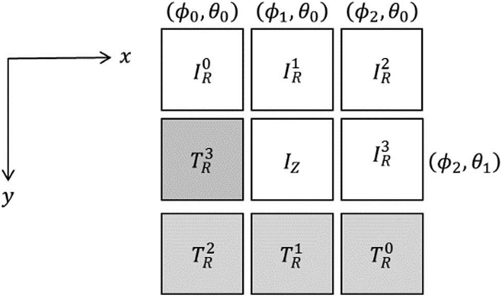
In so far, a sampled phase-only hologram (SPOH) can only be used to represent a single source image. It will be desirable if the storage capacity of the SPOH can be used to embed multiple images. Such a possibility has been explored in Ref. [16], with which angular multiplexing is adopted to store multiple images in a single amplitude-only hologram. A brief outline of the method is given as follows. Suppose there are sources images, denoted by . A Fresnel hologram is first generated for each of the images, and an inclined reference plane wave is then added to convert it into an off-axis hologram, where and are the inclined angles of the reference plane wave along the and directions on the hologram plane, respectively. The angle of incidence is set in a way that the reconstructed images of the holograms do not overlap with each other. The set of off-axis holograms is then summed to obtain an integrated hologram, the real part of which is retained as an off-axis amplitude hologram. An example of the reconstructed images of an integrated hologram of four images () is shown in Fig. 1, where denotes the reconstruction of the source image , with representing the zero-order diffraction. A defocused twin image is associated with each reconstructed image.
Figure 1.Positions of the reconstructed images of the four images , represented by the integrated off-axis amplitude hologram.
Despite the effectiveness of this method, it has three major shortcomings. First, as illustrated in Fig. 1, each reconstructed image is accompanied by a defocused twin image. Second, all of the reconstructed and twin images are visible simultaneously at different locations. Hence, the method is not suitable for displaying images one at a time at a fixed position. Third, converting a complex-valued hologram into an amplitude hologram is undesirable, as it results in twin images and reduces the optical efficiency. Alternative methods have been proposed in Refs. [17,18], whereby multiple images that are located at non-overlapping positions are embedded in a digital phase-only and amplitude-only Fresnel hologram, respectively. Similar to Ref. [16], all of the reconstructed images are occupying different locations and visible at the same time. Herein, we propose a new method for integrating multiple images so that the aforementioned problems mentioned in Refs. [16–18] can be overcome. No angular multiplexing is needed for multiple-image storage. Briefly, each image to be integrated in the hologram is first down-sampled with a GC lattice and converted into a Fresnel hologram. Next, each hologram is scrambled via the Arnold transform, after which the holograms are combined into an integrated hologram. Finally, the phase component of the integrated hologram is retained as an integrated SPOH (ISPOH). To display a particular image of the hologram, the inverse Arnold transform associated with that image is applied to the ISPOH and displayed with a phase-only SLM.
Sign up for Chinese Optics Letters TOC. Get the latest issue of Chinese Optics Letters delivered right to you!Sign up now
Our proposed method comprises four stages, as illustrated in Fig. 2. A set of images, each denoted by , is embedded into an ISPOH . We assume that the source images are planar, parallel to the hologram, and located at an axial distance of from the hologram. Details for each stage are presented in Fig. 2.
Figure 2.Proposed method for integrating multiple images into a single phase-only hologram.
Stage 1: Down-sampling the Source Images with a GC Lattice
In this stage, we apply the method reported in Ref. [15], whereby each image is down-sampled with a GC lattice , resulting in a new image given by
In the GC lattice , pixels that satisfy the following criteria are classified as sample points and assigned a value of one, while the rest are set as zero. Let denote the down-sampling factor, , and , with % being the modulus operator. Then, where denotes the logic “OR” operation.
Stage 2: Hologram Generation
In this stage, each down-sampled source image is converted into a Fresnel hologram using the following equation: where is the free-space spatial impulse response of the propagation of light[19], is the pixel size of the hologram, and is the two-dimensional (2D) convolution operator.
Stage 3: Arnold Transform of Holograms
The Arnold transform is an effective method for encrypting an image through scrambling of its pixel locations[20]. In our proposed method, repetitive rounds of the Arnold transform are applied to encrypt each hologram into a new image. In each round of the transform, the pixels of the current image are relocated to new positions. Given an square image with representing the image after rounds of the Arnold transform, a new image is formed by transforming the current image with a matrix , as follows: where and are the transform parameters. For example, if a pixel is previously located at , and at the th iteration with , it is relocated to a new position at and after the transform. The pixel can be reverted to its previous position using the inverse Arnold transform:
Referring to the previous example, the pixel at and at the th iteration is reverted to its previous position at according to Eq. (5). The th hologram, after rounds of the Arnold transform, is denoted as . Each hologram is transformed with a different round of the Arnold transform (i.e., if ), so that each hologram is encrypted differently.
Stage 4: Generating the ISPOH
The Arnold-transformed holograms are summed into a single hologram , and the phase component is retained as an ISPOH given by where denotes the argument, i.e., the phase of the complex quantity being bracketed. The value , which corresponds to the number of Arnold transformations on the th hologram, will be taken as the unique key parameter for retrieving the th hologram from the ISPOH.
To retrieve the th hologram from the ISPOH, the pixels in are relocated by applying Eq. (5) for rounds (i.e., the unique key parameter), resulting in a phase-only hologram . Among all of the holograms embedded in , only the one corresponding to is reverted to an approximation of , which is denoted as . The rest of the embedded holograms, which are not decrypted with the correct number of rounds of the inverse Arnold transform, remain as noise data. The result is only an approximation owing to the contamination of the noise data, and distortion occurs because of the removal of the magnitude component from the integrated hologram in Eq. (6). From , an approximation of the source image —denoted as —can be reconstructed. To avoid the zero-order beam upon reconstruction, is converted into an off-axis hologram via multiplication with a plane wave that is inclined at an angle along the vertical direction, as follows:
From , an approximation of the source image can be optically reconstructed with a phase-only SLM or numerically reconstructed by convolving with the conjugate of the free-space impulse response, as follows: where denotes the complex conjugate of .
Four source images to , as shown in Figs. 3(a)–3(d), are employed to demonstrate the effectiveness of our proposed method. The images are located at an axial distance of from the hologram. Each image is down-sampled with a GC lattice using the sampling factor and converted into a Fresnel hologram using Eq. (3). The pixel size is 6.4 μm, and the wavelength of light is 520 nm. Next, Eq. (4) is applied to transform each hologram with rounds of the Arnold transform (where is the index of each image) with and . We assigned so that each hologram is transformed differently from the others and can be separated from the inverse Arnold transform at a later stage. Subsequently, the transformed holograms are summed, and the phase component is extracted to obtain the ISPOH, . Each of the phase-only holograms corresponding to is recovered by applying rounds of the inverse Arnold transform to the ISPOH , resulting in the phase-only hologram . By applying Eq. (7), an inclined plane with is added to , resulting in the off-axis hologram . The numerically reconstructed images of the four holograms from (with ) are shown in Figs. 4(a)–4(d). Apart from the down-sampling and mild noise contamination, all of the images were successfully reconstructed. The optically reconstructed images of the ISPOH, which is based on a proprietary SLM of identical size and resolution to the hologram and is illuminated with a coherent 520 nm plane wave, are shown in Figs. 5(a)–5(d). Apart from some minor distortion that is caused by the imperfection of the optical setups, the optically and numerically reconstructed images are similar.
As a conclusion, we have proposed a method for generating an ISPOH that is capable of embedding multiple images into a single hologram. Each embedded image can be reconstructed with favorable visual quality by first applying the corresponding rounds of the inverse Arnold transform to the ISPOH, followed by either numerical reconstruction or optical hologram reconstruction using a phase-only SLM. Experimentally, four images were embedded in an ISPOH generated by using the proposed method. Apart from slight degradation of the reconstructed image, the visual quality of the reconstructed images is generally favorable. The proposed method can be employed to integrate more images, at the expense of increasing the noise contamination of the reconstructed images. The degradation on the reconstructed image will become increasingly prominent after over four images. In general, about eight images can be embedded with acceptable quality. In passing, we would like to mention that our proposed method can also be applied to embed multiple images on a complex-valued hologram. However, an ISPOH has the advantage that it can be displayed with a single phase-only SLM.
P. W. M. Tsang, T.-C. Poon, W. Wang, X. Zhu, K. Chan. Integrating multiple images in a sampled phase-only hologram[J]. Chinese Optics Letters, 2019, 17(5): 050901