
Xingchen Zhao, Xiaoyu Nie, Zhenhuan Yi, Tao Peng, Marlan O. Scully. Imaging through scattering media via spatial–temporal encoded pattern illumination[J]. Photonics Research, 2022, 10(7): 1689
- Photonics Research
- Vol. 10, Issue 7, 1689 (2022)
Abstract
1. INTRODUCTION
Optical imaging through turbid media has various applications, from long-range observations through turbulence to imaging inside living tissues [1–5]. In turbid media, light waves are distorted due to inhomogeneities, resulting in a loss of spatial resolution and reduced imaging depth. Low-order aberrations due to random refractive index fluctuations can be overcome by adaptive optics [6] and turbulence-free ghost imaging [7], while the problem becomes intractable for optically opaque media in which strong light scattering scrambles the spatial information conveyed by light fields. Early experiments using holographic imaging [8] demonstrated that scattering by stationary media does not erase spatial information carried by light fields [9]. Speckle patterns appear random but are essentially deterministic, and information about the optical input can be retrieved. Recent advances in wavefront shaping exploiting transmission matrices [10–14] and optical phase conjugation [15–19] have enabled focusing and imaging through scattering media. However, they are either invasive and require holographic or interferometric measurements or need prior knowledge of the scattering properties of the media. Recent developments taking advantage of the angular correlation of speckle patterns [20–22], i.e., “memory effect,” enable non-invasive imaging through scattering layers using the auto-correlation of speckle patterns and a phase retrieval algorithm [23–26]. Even though these techniques do not rely on the scattering properties of the media, they share some shortcomings. For example, the memory-effect range restricts this approach to thin scattering layers, the small single speckle grain requires a high-resolution camera to resolve, and the iterative phase-retrieval algorithm suffers from falling into local optimal solutions.
In addition, the dynamic nature of some media, such as fog and biological tissues, introduces another aspect to the challenge: the mapping between input and output fields becomes time dependent, resulting in a rapid decorrelation of optical output information. The vision through the turbid medium between the object and camera has been realized through speckle correlation and shower curtain effects [27]. However, this method fails when the medium between the source and the object is also dynamic. Alternatively, ultrasound-modulated light correlation can be used to image an object hidden inside dynamic media [28]. Nevertheless, the measurements are carried out using raster scans, thus causing a very slow imaging speed. Therefore, fast imaging modalities of objects completely immersed in dynamic media are still in high demand.
In this study, we describe a technique for computational imaging, called spatial–temporal encoded pattern (STEP) illumination, which allows noninvasive imaging through scattering media. We demonstrate experimentally that an image of an object can be reconstructed from a 1D time series of light intensity measured by a photodetector (PD), using ground glass diffusers and slices of chicken breast (1.2 mm thick each) as scattering media.
Sign up for Photonics Research TOC. Get the latest issue of Photonics Research delivered right to you!Sign up now
2. PRINCIPLE
Enlightened by the concepts of intensity modulation and Fourier transform (FT)-based discrimination [29], we design a sequence of patterns that consists of a bundle of sinusoidal time series with different frequencies. Every spatial location in each pattern is encoded by a unique frequency, a unique feature of the periodic oscillation of the pixel values along the “time” axis (i.e., looking at a single spatial location through different patterns). We illuminate the diffuser–object system with this sequence of patterns and collect the transmitted light by a single-pixel detector. The images of the objects are retrieved based on the fast FT (FFT) algorithm without knowledge of the object or scattering medium.
The design of STEP and the principle of image reconstruction are sketched in Fig. 1. We generate a sequence of grayscale (8-bit, 256 pixel values) patterns of height and width ( matrix). For a spatial location (th row, th column), the time series is given by
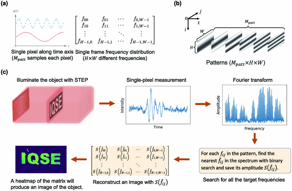
Figure 1.Design of STEP and principle of image reconstruction. (a) Sequence of patterns consisting of a bundle of sinusoidal time series with unique frequencies at each spatial location. (b) Grayscale pattern sequence used to image an object through scattering media. (c) The object is first illuminated by STEP. The intensity of the transmitted light
3. RESULTS
A schematic of the experiment setup is shown in Fig. 2(a). The grayscale patterns are first decomposed to monochrome (1-bit, two pixel values) patterns to be compatible with the input format of the DMD. A solid-state laser (633 nm) with a power of is used to illuminate the DMD, which spatially modulates the incident laser beam and generates a set of illumination projections with a spatial structure similar to the input monochrome patterns. Each projection has , and each pixel is maintained by a array of DMD micromirrors (each micromirror has a size of ). We define such an array of mirrors as a single “DMD pixel.” The patterns are then imaged by a lens (L1) with a magnification of two. High-order images due to diffraction are filtered out by an iris (I) such that only the zeroth-order image with the strongest intensity is formed in the image plane. A high-contrast object (O) with letters “IQSE” () being transparent is placed at the image plane of L1, where the zeroth-order images of the patterns are directly projected on the region of “IQSE” without scattering media. Then, two ground glass diffusers (D1 and D2, 220 grit) are inserted to block the view of the object. The 1 mm thick ground glass diffusers with a 220 grit size are considered as standard highly scattering media [24,30]. The distances between the object and D1 and D2 are about 1 mm and 5 mm, respectively. The diffusers can be kept stationary or moved back and forth at a random speed by a motorized stage. A lens (L2) followed by a PD is placed behind D2 to collect the transmitted light. The system is synchronized. The PD will record the intensity each time a pattern is applied to the DMD.
![]()
Figure 2.Experimental demonstration of STEP with ground glass diffusers. (a) Schematic of the setup. DMD, digital micromirror device; L1 and L2, lenses; I, iris; D1 and D2, diffusers; O, object; PD, photodetector. (b) Images captured by a CMOS camera under three conditions: without scattering media (ND), with stationary diffusers (SD), and with dynamic diffusers (DD). (c) Images reconstructed by STEP with
The image of the object is first captured by a CMOS camera (replacing the PD) under three conditions: without scattering media (ND), with stationary diffusers (SD), and with dynamic diffusers (DD). As shown in Fig. 2(b), the object is invisible in the camera images when the diffusers are present (SD and DD), while the STEP imaging scheme can retrieve the images through both SD and DD [Fig. 2(c)]. We define as a scaled number of patterns, in which is the number of grayscale patterns, and is the number of pixels in one pattern. The measurements in Fig. 2(c) are performed with , i.e., 9600 grayscale patterns ( monochrome patterns), and . To reconstruct an image, the frequency resolution of the FT must satisfy the condition , which determines the minimum value of . Our experimental parameters (, , ) give . Images in Fig. 2(b) are obtained with . Raw pixels in the reconstructed image are always the same as those in the patterns. Such a small number of pixels leads to pixelated images. Nevertheless, the pixelation effect can be eliminated computationally by applying bilinear interpolation to the raw pixels, and interpolated images of size are given in the second column of Fig. 2(c) for each .
The size of an individual pixel determines the imaging resolution in the patterns projected onto the object: the smaller the pixel is, the more details of the object can be resolved. The pixel size at the image plane of L1 is determined by the size of the DMD pixel and the magnification of the imaging system defined by L1 when there are no scattering media. Decreasing the DMD pixel size will increase the resolution for a given magnification. However, the optical power reflected by each DMD pixel will be reduced due to the shrinkage of the reflective area (fewer micromirrors), resulting in a decreased signal-to-noise ratio (SNR) of the measured light. Conversely, increasing the DMD pixel will provide better SNR at the expense of a lower resolution. If the scattering layers are inserted, the degradation of pattern quality and the attenuation of optical power due to scattering must also be considered. Therefore, the trade-off between resolution and SNR should be decided according to the configuration of a specific setup and the optical properties of the media. In our experiment, the resolution is , which is adequate for resolving the object of size , and the transmitted light intensity is far above the shot noise level of the detector under the scattering of 220 grit ground glass diffusers and 1.2 mm thick chicken breast slices.
To further demonstrate that STEP is also insensitive to the motion of the scattering centers in the media, we replaced the ground glass diffusers in Fig. 2(a) with two slices of chicken breast and performed similar measurements with . In general, chicken breast has the following optical properties for light at a wavelength of 633 nm [18]: scattering coefficient 23 mm−1, reduced scattering coefficient 0.8 mm−1, and absorption coefficient 0.01 mm−1. These parameters imply that scattering is the dominant process that prevents the tissue from being transparent. As shown in Fig. 3(b), the object cannot be resolved in the camera image, whereas the image can be reconstructed by STEP [Fig. 3(c)]. The larger the , the better the spectrum’s ability to distinguish target frequencies from background noise. A much larger to perform the computation implies stronger tissue scattering than in the ground glass diffusers. In the reconstructed image, some bright spots appear due to the uneven texture of the tissue, which results in less evenly distributed transmitted light intensity than for the ground glass diffusers. Nevertheless, the results suggest that STEP can image through dynamic scattering media.
![]()
Figure 3.Imaging through two slices of chicken breast (
We define the visibility of the reconstructed image to be , in which and are the average pixel values of the signal (“IQSE” regions) and background (other regions), respectively. Different from conventional structured illumination techniques in which the information required for image reconstruction is encoded only in the spatial structure of the patterns [31–35], the STEP illumination also encodes the information (frequencies) in time. One advantage of introducing the time-domain encoding is that it allows further improvement of the visibility via halving a successive segment of the data and calculating the cross-spectrum (CS) of the two halves. The cross-correlation technique has been demonstrated very effective in weak signal detection [36–38]. For images reconstructed with a specific , higher visibility is obtained if the searching of target frequencies is performed in the CS of the two halves of the data [Fig. 4(b)] rather than in the Fourier spectrum of all the data [Fig. 4(a)]. As shown in Fig. 4(b), we divide the whole data set into two segments of the same length, and their cross-correlation is found to be
![]()
Figure 4.Comparison of different image reconstruction algorithms. (a) Fourier transform (FT): a segment of
The image reconstruction can also be implemented by calculating the correlations between the measured intensity data and the time series in the original patterns [31,32,35]:
The correlation method also suffers from low computational efficiency. For patterns of size , both the time and space complexity of the image reconstruction via correlation are , in terms of the big-O notation, whereas the time complexity of FFT-based reconstruction (FT and CS) is since the FFT algorithm is used to compute the spectrum, and the space complexity is , as there is no need to store the original patterns. A benchmark of the computing time for FFT-based and correlation algorithms is given in Fig. 4(e), where the rapid increase in computing time for the correlation algorithm provides a sharp contrast with those of FFT-based methods. The high computational efficiency of the FFT-based algorithm may enable fast image processing with devices having limited computing resources.
4. CONCLUSION
In conclusion, we have developed a computational imaging method named “STEP” to realize non-invasive imaging through scattering media with a single-pixel PD. We have demonstrated the ability of imaging an object sandwiched between two opaque scattering glass diffusers, as well as for the same object embedded in chicken breast layers, where the light experienced multiple scattering. This method is insensitive to the motion of the scattering centers in the media. The design of STEP removes the requirement of a high-resolution camera. It allows an elegant FFT-based image reconstruction algorithm that is more computationally efficient than correlation-based methods, which may be more favorable in many application fields. Our technique provides new perspectives for peeking through multiple scattering turbid media and enables potential fast images to diagnose biological tissues.
References
[1] A. W. Lohmann, G. Weigelt, B. Wirnitzer. Speckle masking in astronomy: triple correlation theory and applications. Appl. Opt., 22, 4028-4037(1983).
[2] Z.-P. Li, X. Huang, Y. Cao, B. Wang, Y.-H. Li, W. Jin, C. Yu, J. Zhang, Q. Zhang, C.-Z. Peng, F. Xu, J.-W. Pan. Single-photon computational 3D imaging at 45 km. Photon. Res., 8, 1532-1540(2020).
[3] Z.-P. Li, J.-T. Ye, X. Huang, P.-Y. Jiang, Y. Cao, Y. Hong, C. Yu, J. Zhang, Q. Zhang, C.-Z. Peng, F. Xu, J.-W. Pan. Single-photon imaging over 200 km. Optica, 8, 344-349(2021).
[4] V. Ntziachristos. Going deeper than microscopy: the optical imaging frontier in biology. Nat. Methods, 7, 603-614(2010).
[5] S. Yoon, M. Kim, M. Jang, Y. Choi, W. Choi, S. Kang, W. Choi. Deep optical imaging within complex scattering media. Nat. Rev. Phys., 2, 141-158(2020).
[6] R. K. Tyson. Principles of Adaptive Optics(2011).
[7] R. E. Meyers, K. S. Deacon, Y. Shih. Turbulence-free ghost imaging. Appl. Phys. Lett., 98, 111115(2011).
[8] E. N. Leith, J. Upatnieks. Holographic imagery through diffusing media. J. Opt. Soc. Am., 56, 523(1966).
[9] I. Freund. Looking through walls and around corners. Physica A, 168, 49-65(1990).
[10] S. M. Popoff, G. Lerosey, R. Carminati, M. Fink, A. C. Boccara, S. Gigan. Measuring the transmission matrix in optics: an approach to the study and control of light propagation in disordered media. Phys. Rev. Lett., 104, 100601(2010).
[11] S. Popoff, G. Lerosey, M. Fink, A. C. Boccara, S. Gigan. Image transmission through an opaque material. Nat. Commun., 1, 81(2010).
[12] J. Yoon, K. Lee, J. Park, Y. Park. Measuring optical transmission matrices by wavefront shaping. Opt. Express, 23, 10158-10167(2015).
[13] H. B. de Aguiar, S. Gigan, S. Brasselet. Enhanced nonlinear imaging through scattering media using transmission-matrix-based wave-front shaping. Phys. Rev. A, 94, 043830(2016).
[14] M. Kim, W. Choi, Y. Choi, C. Yoon, W. Choi. Transmission matrix of a scattering medium and its applications in biophotonics. Opt. Express, 23, 12648-12668(2015).
[15] G. S. He. Optical phase conjugation: principles, techniques, and applications. Prog. Quantum Electron., 26, 131-191(2002).
[16] Z. Yaqoob, D. Psaltis, M. S. Feld, C. Yang. Optical phase conjugation for turbidity suppression in biological samples. Nat. Photonics, 2, 110-115(2008).
[17] D. Wang, E. H. Zhou, J. Brake, H. Ruan, M. Jang, C. Yang. Focusing through dynamic tissue with millisecond digital optical phase conjugation. Optica, 2, 728-735(2015).
[18] T. R. Hillman, T. Yamauchi, W. Choi, R. R. Dasari, M. S. Feld, Y. Park, Z. Yaqoob. Digital optical phase conjugation for delivering two-dimensional images through turbid media. Sci. Rep., 3, 1909(2013).
[19] I. M. Vellekoop, M. Cui, C. Yang. Digital optical phase conjugation of fluorescence in turbid tissue. Appl. Phys. Lett., 101, 081108(2012).
[20] I. Freund, M. Rosenbluh, S. Feng. Memory effects in propagation of optical waves through disordered media. Phys. Rev. Lett., 61, 2328-2331(1988).
[21] G. Osnabrugge, R. Horstmeyer, I. N. Papadopoulos, B. Judkewitz, I. M. Vellekoop. Generalized optical memory effect. Optica, 4, 886-892(2017).
[22] H. Liu, Z. Liu, M. Chen, S. Han, L. V. Wang. Physical picture of the optical memory effect. Photon. Res., 7, 1323-1330(2019).
[23] J. Bertolotti, E. G. van Putten, C. Blum, A. Lagendijk, W. L. Vos, A. P. Mosk. Non-invasive imaging through opaque scattering layers. Nature, 491, 232-234(2012).
[24] O. Katz, P. Heidmann, M. Fink, S. Gigan. Non-invasive single-shot imaging through scattering layers and around corners via speckle correlations. Nat. Photonics, 8, 784-790(2014).
[25] M. Cua, E. H. Zhou, C. Yang. Imaging moving targets through scattering media. Opt. Express, 25, 3935-3945(2017).
[26] X. Li, A. Stevens, J. A. Greenberg, M. E. Gehm. Single-shot memory-effect video. Sci. Rep., 8, 13402(2018).
[27] E. Edrei, G. Scarcelli. Optical imaging through dynamic turbid media using the Fourier-domain shower-curtain effect. Optica, 3, 71-74(2016).
[28] H. Ruan, Y. Liu, J. Xu, Y. Huang, C. Yang. Fluorescence imaging through dynamic scattering media with speckle-encoded ultrasound-modulated light correlation. Nat. Photonics, 14, 511-516(2020).
[29] S. Sudarsanam, J. Mathew, S. Panigrahi, J. Fade, M. Alouini, H. Ramachandran. Real-time imaging through strongly scattering media: seeing through turbid media, instantly. Sci. Rep., 6, 25033(2016).
[30] X. Wen, S. Adhikari, C. L. Cortes, D. J. Gosztola, S. K. Gray, G. P. Wiederrecht. Ghost imaging second harmonic generation microscopy. Appl. Phys. Lett., 116, 191101(2020).
[31] B. Sun, M. P. Edgar, R. Bowman, L. E. Vittert, S. Welsh, A. Bowman, M. J. Padgett. 3D computational imaging with single-pixel detectors. Science, 340, 844-847(2013).
[32] V. Durán, F. Soldevila, E. Irles, P. Clemente, E. Tajahuerce, P. Andrés, J. Lancis. Compressive imaging in scattering media. Opt. Express, 23, 14424-14433(2015).
[33] Z. Zhang, X. Ma, J. Zhong. Single-pixel imaging by means of Fourier spectrum acquisition. Nat. Commun., 6, 6225(2015).
[34] X. Hu, H. Zhang, Q. Zhao, P. Yu, Y. Li, L. Gong. Single-pixel phase imaging by Fourier spectrum sampling. Appl. Phys. Lett., 114, 051102(2019).
[35] G. M. Gibson, G. M. Gibson, S. D. Johnson, S. D. Johnson, M. J. Padgett, M. J. Padgett. Single-pixel imaging 12 years on: a review. Opt. Express, 28, 28190-28208(2020).
[36] Y. Li, B. Yang, P. Lu, S. Li. Detecting technique of weak periodic pulse signal via synthesis of cross-correlation and chaotic system. J. Electron., 20, 397-400(2003).
[37] M. A. Razak. Detection and extraction of weak signals buried in noise. Am. J. Phys., 77, 1061-1065(2009).
[38] P. Rudnick. The detection of weak signals by correlation methods. J. Appl. Phys., 24, 128-131(1953).

Set citation alerts for the article
Please enter your email address
© Copyright 2018-2021 | Chinese Laser Press. All Rights Reserved 沪ICP备15018463号-20