
Junyu Qian, Pengfei Wang, Yujie Peng, Yanyan Li, Beijie Shao, Hongpeng Su, Xinlin Lv, Ding Wang, Yuxin Leng, Ruxin Li. Pulse combination and compression in hollow-core fiber for few-cycle intense mid-infrared laser generation[J]. Photonics Research, 2021, 9(4): 477
- Photonics Research
- Vol. 9, Issue 4, 477 (2021)
Abstract
1. INTRODUCTION
Few-cycle laser pulses with ultra-intense peak power at the mid-infrared (MIR) wavelength (especially from 3 to 5 μm) have attracted extensive interest due to their considerable potential applications in many areas of strong-field physics, including the extension of cut-off energy to the keV regime in high-harmonic generation (HHG) experiments [1], generation of broadband and isolated ultrashort coherent soft X-ray [2], and high-efficiency emission of THz pulses [3]. In order to generate high-quality MIR pulses with desirable parameters, several laser techniques have been demonstrated in which the optical parametric chirped pulse amplification (OPCPA) system provides an ideal approach that is able to deliver gigawatt-level MIR pulses [4–7]. However, the power scaling ability of conventional one-channel OPCPA systems is restricted by several effects [8,9] such as the limited apertures of nonlinear crystals and the damage threshold of optical elements used in the setups. Therefore, the output power of a single OPCPA is limited, and it is necessary to further increase the output power through beam combination.
The coherent beam combination (CBC) technique [10,11], as one of the most promising approaches toward 100 petawatt or even exawatt pulse generation [12–14], is able to break out the limitation on achievable pulse peak power and field intensity. In a parallel CBC configuration (also referred to as far-field CBC configuration), the peak power of output pulses can in principle be enhanced by N times, where N is the channel number used in the CBC system. Although the CBC technique was widely used in near-infrared (NIR) laser systems [15–18], few studies have reported on MIR laser systems so far. Actually, the CBC technique has more potential for MIR lasers than for NIR lasers given its greatest advantage of lower temporal synchronization requirement due to longer field oscillation period and pulse width of MIR lasers [19–21]. On the other hand, in traditional CBC systems, the intensity is strongly spatially modulated in the focal plane because of the interference effect and spatial phase distortions [22], which certainly might decrease the focused intensity and the Strehl ratio of the combined pulse. Furthermore, a nonlinear pulse-shortening approach with gas-filled hollow-core fiber (HCF) has been highly desirable for the generation of few-cycle high-peak-power pulses, which can improve the beam profile of the output laser because of the mode-filtering effect of the HCF itself. For all these reasons, the marriage of CBC and HCF techniques comes naturally and deservedly, and can greatly improve the peak power and beam profile, especially for intense MIR lasers.
In this paper, we demonstrate a properly designed CBC setup based on an HCF in which two MIR (4 μm) pulses with identical pulse parameters are coherently combined using a traditional parallel CBC configuration, and then the temporal duration of the combined pulse is compressed by the strong nonlinearity inside the HCF into the few-cycle regime. Briefly, two congenetic MIR pulses with tens-of-cycles pulse duration generated from two parallel OPCPA systems are coherently combined at the input port of the HCF. Afterwards, the combined MIR pulse propagates into a long gas-filled HCF. The strong nonlinearity driven by the intense pulse and high-pressure gas is responsible for a spectral broadening that extends to near an octave. Finally, residual chirps of this spectral-broadened pulse are properly compensated using a crystal [23,24], leading to the generation of sub-two-cycle pulses (22.9 fs, corresponding to 1.7 optical cycles). Due to the efficient pulse compression process in the HCF, the peak power of the combined pulse is further increased compared with the individual pulse peak power in this HCF-based CBC setup. In addition, with spatial filtering effects of the HCF, the output beam profile expectedly approximates the Gaussian shape without any intensity modulation. At the same time, the almost perfect spatial and temporal coherences of the combined beam are verified. The technique presented in this paper can be scaled up to generate higher-peak-power MIR lasers with few-cycle duration for strong-field physics and other applications.
Sign up for Photonics Research TOC. Get the latest issue of Photonics Research delivered right to you!Sign up now
2. EXPERIMENT SETUP
The schematic of the OPCPAs and the HCF-based CBC setup is depicted in Fig. 1. The 4 μm laser pulses are from a home-built optical parametric amplification (OPA) device pumped by a commercial Ti:sapphire laser (Astrella, Coherent Inc.) [25]. The pulses are stretched in the time domain by means of an Öffner-type reflection-grating stretcher to 60 ps. The stretched pulses are separated into two portions by a beam splitter and used as the signal pulses of the following two OPCPA systems. The pump pulses are from a commercial picosecond Nd:YAG laser (APL 2105, EKSPLA Inc.), which can deliver 1064 nm laser pulses with total energy of 250 mJ and pulse duration of 65 ps at 20 Hz. Each OPCPA system has two amplified stages and both are based on 10 mm thick KTA crystals, which are cut at for type II phase matching. Then, the amplified pulses with 4.42 and 5.1 mJ energy are injected into two similar grating-pair compressors. After compression, two pulses with 3.38 and 3.5 mJ energy from each OPCPA channel can be obtained. The repetition rates of the OPCPA systems are 20 Hz. The duration of each initial pulse is about 120 fs, which is tunable from 120 fs to 2 ps by adjusting the distance of the grating pairs for the following experiments.
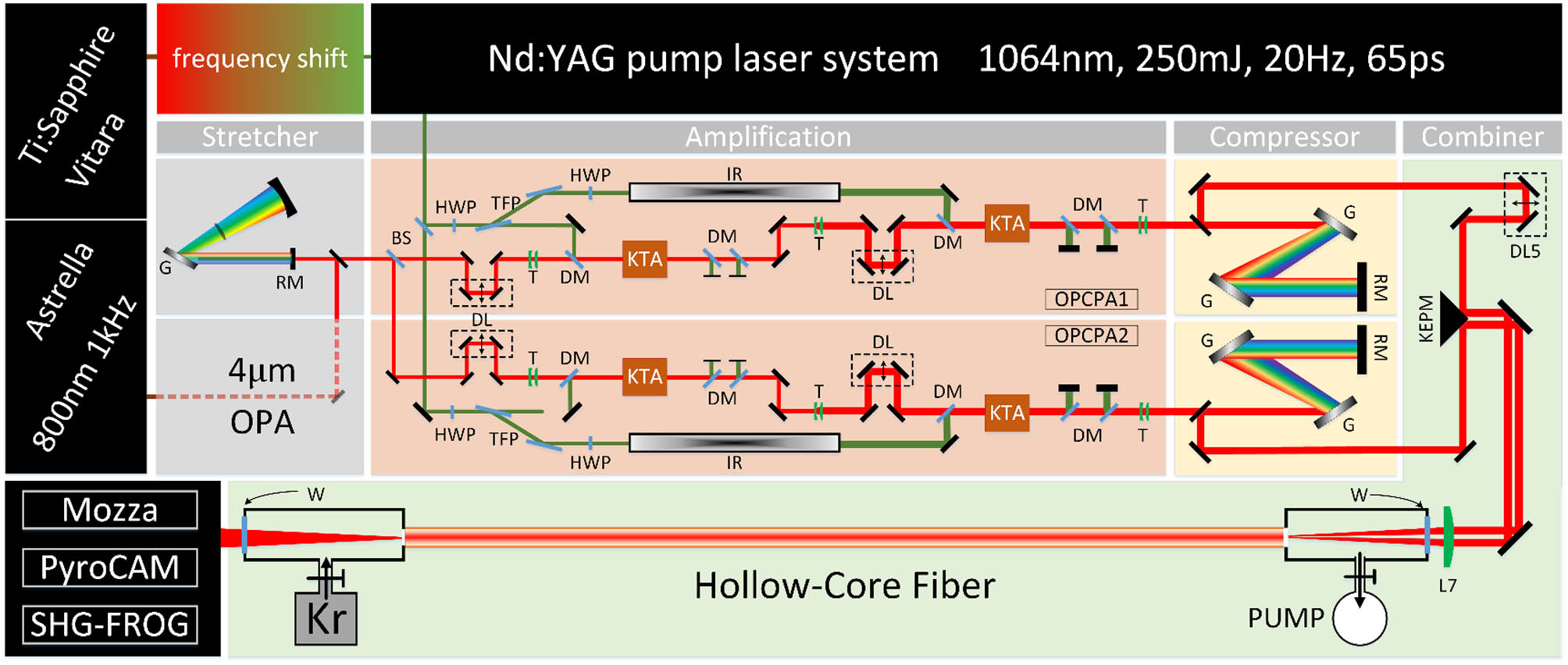
Figure 1.Schematic of the 4 μm OPCPA system and the HCF-based CBC system. KTA, KTiOAsO4 crystal; DL, delay line; HWP, half-wave plate; TFP, thin film polarizer; DM, dichroic mirror; T, telescope; W, CaF2 window; IR, image relay; BS, beam splitter; RM, roof mirror; G, grating; KEPM, knife edge prism mirror; L, lens; Kr, krypton.
Subsequently, the two congenetic 4 μm pulses with the same characteristics, such as energy (each 2.8 mJ), pulse durations (each 160 fs with slight positive chirp), horizontal polarizations, spectra, and beam sizes, are preliminarily combined in the focal plane of an lens (called “L7” in Fig. 1), which is also called the “combining lens” in the CBC regime or the “coupling lens” in the HCF regime. A motorized precision delay line, “DL5”, is utilized to align the two pulses overlapping in the focal plane. The combined pulse is gathered by a krypton-filled HCF with a static pressure. In order to reduce the linear propagation losses in HCF and enlarge the nonlinear coefficient [26] simultaneously, we chose the HCF with 1 mm inner-core diameter and about 2.8 m length (Few-cycle Inc.). To get the maximum coupling efficiency, the ratio between the beam waist radius and the HCF inner-core radius plays an important role [27]. In this experiment, the focused spot diameter at the HCF inlet is controlled at 0.63 mm. The nonlinear coefficient is continuously adjusted by changing the krypton pressure, which is controlled precisely and monitored in real time.
In order to get stronger nonlinear effects and broader spectrum in HCF, the negative dispersion caused by HCF structure [26] and the bulk material before the HCF, such as the window plate and the coupling lens, should be well pre-compensated. Therefore, the durations of individual pulses are controlled at 160 fs (FWHM) with slight positive chirp. This reduces the input pulse peak power below the self-focusing critical power so as to avoid higher-order nonlinear effects and ionization effect during the pulse propagation in the HCF. During the propagation, the spectrum of the combined pulse is broadened to near one octave by the intense self-phase modulation (SPM) effect. The broadened spectrum is broad enough to support sub-two-optical-cycle pulse generation. Finally, a 2 mm thick is employed as the output window of the HCF, which can introduce a certain amount of negative dispersion to compress the combined pulse duration to sub-two-optical-cycle level.
Finally, a silver concave mirror is used to collimate the output beam for measurements. The temporal and spectral characterizations of the final compressed pulse are measured and diagnosed by a home-built second-harmonic generation frequency-resolved optical-gating (SHG-FROG) device [24,28] and an MIR spectrometer based on an acousto-optic dispersive filter (MOZZA, Fastlite Inc.).
3. EXPERIMENT RESULTS AND DISCUSSION
As the two pulses with total 5.6 mJ energy are injected into the HCF, a pulse with nearly 2.7 mJ (1.35 and 1.34 mJ for each pulse) is obtained at the output side, corresponding to a total transmission of 47.7%. The krypton pressure does not visibly affect the HCF transmission during the pressure changing from 0 to 2.5 bar (1 bar = 10 kPa). This HCF system is especially suitable for MIR laser pulse compression with high energy and high peak power, because the self-focusing critical power scales with wavelength as . The amount of spectral broadening in the HCF is mainly decided by the nonlinear phase shift B, which can be controlled by changing the filling krypton pressure. We analytically estimate the nonlinear phase shift B and corresponding broadening factor under our experimental conditions. The nonlinear phase shift presents as follows:
As a near Fourier-transform limited (FTL) pulse is injected to the HCF (), the group delay dispersion (GDD, ) of the output pulse resulting from the SPM is given by the following formula [31]:
So, with about 2.2 bar krypton filled in the 2.8 m long HCF, . Therefore, the required thickness for GDD compensation is 1.98 mm for 4 μm central wavelength, and 2 mm thickness is chosen finally.
The spectrum broadening factor due to SPM in the krypton-filled HCF can be calculated as [31]
With perfect phase compensation, the output FTL pulse duration can be calculated as
Actually, in the experiments, the measured spectra and corresponding pulse temporal profiles of the combined pulse at the HCF output window with the increasing of krypton pressure in HCF are summarized in Fig. 2. With the krypton pressure increasing in HCF, the spectral broadening of the combined pulse becomes obvious [Figs. 2(a) and 2(c)], and pulse temporal compression becomes significant [Fig. 2(b)] in the meantime. For instance, at the pressure of 2.2 bar, the spectrum of the combined pulse output from the HCF is broadened, spanning from 3.0 to 5.0 μm, which is near an optical octave. The pulse duration is compressed to 22.9 fs (FWHM) through the 2 mm thick window. The actually measured pulse duration, the FTL duration corresponding to the broadened spectrum, and the estimated FTL duration by Eq. (5) at different pressures, are shown in Fig. 2(d). It shows that, when the krypton pressure exceeds 1 bar, the experimental results are in good agreement with the theoretical ones. With krypton pressures increasing over 1.8 bar, the broadened spectrum is broad enough to support sub-two-optical-cycle pulse duration. The differential between blue and green dots is because the dispersion of the output pulse is not well compensated, and the difference between the red curve and green dots at a low krypton pressure is because the initial chirps of the input pulse cannot be ignored in Eq. (3).
![]()
Figure 2.(a) Spectra measured by MOZZA and (b) corresponding temporal profiles measured by SHG-FROG at different krypton pressures. (c) Spectral evolution throughout increasing gas pressures output from the HCF measured by SHG-FROG. (d) The measured compressed pulse durations with 2 mm CaF2 (blue curve), corresponding FTL duration (green curve), and estimated FTL duration (red curve) for different krypton pressures. Dashed line represents 26 fs, corresponding to two optical cycles for 4 μm laser pulse.
Therefore, the optimal compression was achieved for 2.2 bar pressure, input pulse durations of 160 fs for both pulses, and employing a 2 mm thick crystal as the output window. The measured and retrieved spectrograms are shown in Figs. 3(a) and 3(b), respectively. Instead, we show the temporal [Fig. 3(c)] and spectral [Fig. 3(d)] pulse amplitude and phase. From the results, we concluded that the pulse duration was 22.9 fs ( RMS error over a calculation grid), corresponding to 1.7 optical cycles. This is very close to the expected FTL duration (1.04 FTL, ), which is also in good agreement with the estimated result mentioned previously, and the peak power of the final output pulse is about 120 GW, which is 6 times that of the single channel ().
![]()
Figure 3.Temporal and spectral characterizations of the compressed pulse. (a) Measured and (b) reconstructed SHG-FROG traces. (c) Blue curve, pulse temporal profile of 22.9 fs duration (FWHM); green curve, retrieved phase. (d) Blue curve, reconstructed spectrum of SHG-FROG; red curve, directly measured spectrum by MOZZA; green curve, retrieved phase.
We measured the incident and output energy stability of the HCF. The energy stability was 2.89% (RMS) for the total incident pulse of 5.6 mJ, while the exit energy was 2.7 mJ with the energy stability of 2.50% (RMS). The HCF does not have an obvious impact on the energy stability, and the CBC transmittance maintains good stability. In addition, we measured the beam combination transmittance of HCF many times within a few days, and all of them maintained nearly 47%. Further, we also measured the pulse width several times over several days, and the HCF output pulse width in all cases could reach below two cycles. Therefore, it can be shown that the output power of our combined beam system can maintain a good stability.
We also characterized the relationship of the far-field pattern in the focal plane of L7 and the relative phase of the individual pulses in the CBC regime, as shown in Fig. 4. In the beginning, the near-field and far-field patterns are present in Figs. 4(a) and 4(c). As changed, the far-field pattern changed periodically. For instance, for , the far-field pattern is shown in Fig. 4(c). In the first half period, , a lobe beam would emerge beside the right (or the left) of the main combined beam. With increase of , the pulse energy transferred from the main beam to the right (or the left) sidelobe. At , there exist two beams with the same energy in the focal plane, which is shown in Fig. 4(b). At the last half period, the energy continuously flows into the right (or the left) lobe. The right beam (or the left) becomes the new main beam at the beginning of the next period, . Compared to Fig. 4(b), Fig. 4(c) shows that the combined beam profile does not present any obvious lobes. also indicates the maximal obtained peak intensity according to previous works [15,19]. Therefore, in all experiments, we controlled the relative phase fixed at , the beam profile of which is shown in Fig. 4(c), by controlling the motorized precision delay line “DL5” accurately.
![]()
Figure 4.(a) Beam profiles before the lens L7. Beam profiles at the focal plane of L7 with the relative phase of the individual pulses (b)
Additionally, with the mode selection and the spatial filtering effects of HCF, the output beam profile approximates a perfect Gaussian distribution without any lobes, as shown in Fig. 4(d). Compared to the strong intensity modulation typically observed in traditional parallel CBC configuration, this profile is more suitable for applications.
Further, a Michelson-type interferometer is employed to verify the temporal and spatial coherences of the compressed pulse, shown in Figs. 4(e) and 4(g). Figures 4(f) and 4(h) represent the interference beam profiles of the temporal and spatial coherence phenomena. We can conclude that the sub-two-cycle pulse exhibits fairly good coherence after the HCF-based CBC system.
The CBC efficiency is normally described by the peak intensity recorded by the spot pattern according to the following equation [16]:
There are two factors which influence the total transmittance of HCF. The first factor is the coupling efficiency, which is related to the quality of the beam spot and the numerical aperture of the HCF. Since the CBC system has two laser beams in parallel, focus-coupled into the HCF, the incident spot is asymmetric along the top–bottom direction and the left–right direction. This will lead to different coupling radii of the combined beam spot at the fiber entrance for the top–bottom and left–right directions, and the numerical aperture is also different. In the left–right direction, we set the coupling radius to 0.64 times the inner diameter of the fiber to match the propagation of the fundamental mode in the fiber, while at the same time, the coupling radius in the top–bottom direction will be smaller than 0.64 times the inner diameter of the fiber, which will result in relatively larger losses.
The other factor is the HCF transmission loss, which is mainly related to the inner diameter of the fiber, incident wavelength, and bending radius of the fiber. The inner diameter of the fiber we use is 1 mm, which can support pulse inputs to mJ or even to tens of mJ order of magnitude, and can effectively ensure high overall transmission efficiency. Meanwhile, the wavelength of our system is 3.9 μm; for longer wavelength, the HCF loss will also be higher. To maintain HCF straightness for a multimeter-long waveguide becomes technically challenging. We employ a stretched waveguide technique using two specially designed mounts that keep the fiber straight within 3 m length. To further improve the transmission efficiency of HCF, we can use larger-aperture fibers and improve our fiber supports to reduce transmission loss in the future.
Furthermore, the output peak power by the HCF based CBC technique can be scaled to much higher values, such as terawatt level in MIR range. At present, HCF with a diameter of 1 mm can support pulse energies of up to tens of mJ [32]. Therefore, CBC based on HCF technology can be further expanded, such as combining four MIR OPCPA systems with 10 mJ energy and 150 fs pulse duration. Then, the four beams are arranged to the four vertices of the square compactly and focused into an HCF by an off-axis parabolic mirror. The temporal and spatial synchronizations of these four beams should definitely be fine controlled. The parameters about the HCF, such as gas pressure and length, can be optimized and manipulated to ensure the compression effect. The combined pulse is spectrally broadened over an octave and compressed through a crystal. From the system, 20 mJ/20 fs laser pulses at 4 μm can be obtained, corresponding to a peak power of more than 1 TW. This scheme of a terawatt-level mid-infrared laser system can be easily realized, and the components are now basically available. Similarly, this technique could be further extended in the future to contain more CBC beam channels, and will provide a guideline for the construction of a high-intensity mid-infrared experiment system.
4. CONCLUSION
In conclusion, we experimentally implement a novel setup combining CBC and nonlinear pulse compression techniques in a length of gas-filled HCF for the generation of few-cycle, high-peak-power MIR laser pulses. We demonstrate that two identical MIR (2.8 mJ/160 fs) pulses, generated from two parallel OPCPA systems, can be coherently combined in the CBC stage; then the combined pulse is strongly compressed in the krypton-filled HCF, leading to the generation of 2.7 mJ energy MIR pulse with simultaneously 1.7 optical cycle duration, ultra-high peak power of more than 100 GW, and repetition rate of 20 Hz. The HCF-based CBC system demonstrated here could be further extended in the future to contain more channels coherently combined and compressed, paving the way to the next generation of ultra-intense MIR laser pulses, which may find tremendous applications in many fields of strong-field physics.
References
[10] T. M. Shay, V. Benham, J. T. Baker, A. D. Sanchez, D. Pilkington, C. A. Lu. Self-synchronous and self-referenced coherent beam combination for large optical arrays. IEEE J. Sel. Top. Quantum Electron., 13, 480-486(2007).

Set citation alerts for the article
Please enter your email address
© Copyright 2018-2021 | Chinese Laser Press. All Rights Reserved 沪ICP备15018463号-20