
Shaokang Bai, Yaqiong Lu, Zuxing Zhang. Mode field switching in narrow linewidth mode-locked fiber laser[J]. Chinese Optics Letters, 2022, 20(2): 020602
- Chinese Optics Letters
- Vol. 20, Issue 2, 020602 (2022)
Abstract
1. Introduction
With the continuous development of the degree of social informatization, the demand for large communication capacity in a highly informatized society is increasing day by day. Multiplexing technology uses the parallelism of electromagnetic waves in various physical dimensions such as time, frequency, quadrature polarization, and space to improve the transmission capacity of optical fiber communication[
In recent years, cylindrical vector beams (CVBs) and orbital angular momentum (OAM) vortex beams with circular intensity distribution have attracted great interest due to their unique polarization and phase distributions. As a distinctive spatial multiplexing dimension, the multiplexing of different orders of CVBs and OAM beams has the potential to achieve larger capacity optical communication[
There are three main ways to generate CVBs in fiber and fiber lasers: misalignment fusion, mode-selective coupler (MSC), and long-period fiber grating (LPFG). Grosjean et al.[
Sign up for Chinese Optics Letters TOC. Get the latest issue of Chinese Optics Letters delivered right to you!Sign up now
In this paper, based on the AOMC driven by the radio frequency (RF) signal, we realized mode-locked pulse output with switchable wavelengths and modes in the ring fiber cavity. The conversion efficiency of AOMC in the 1550 nm mode can reach 12 dB, and the output purity of the mode is 90%. By changing the signal frequency, the mode can be adjusted between different wavelengths. Through the cascade connection between AOMC and FM-FBG, in the mode-locked fiber laser based on the semiconductor saturable absorber mirror (SESAM), the pulse output of different wavelengths and modes is achieved.
2. Experiments and Discussion
For the AOMC, ultrasonic waves generated by electro-acoustic conversion in piezoelectric ceramic propagate along a few-mode fiber, and the refractive index of the fiber produces periodic disturbances. When the ultrasonic wave is at a specific frequency, the AOMC facilitates the mode conversion of the corresponding optical wavelength.
Ultrasonic waves propagate in an optical fiber as acoustic bending waves. A coordinate system is established along the propagation direction of the optical fiber, the bending acoustic wave propagates along the Z axis direction of the optical fiber, and the Y axis is the vibration direction of the bending acoustic wave. The transmission form of the bending acoustic wave in an optical fiber can be expressed as
The beat length of the and modes in the TMF is , where and are the effective refractive indices of the and modes in the TMF (step-index, OFS). When the acoustic wave vector matches the two optical mode wave vectors in the fiber, i.e., , the mode is converted to the mode.
In experiment, a disc type piezoelectric ceramic (PZT) with a resonant frequency of 2 MHz (1876, Shanghai Natao Technology Co., Ltd.) is chosen, on which an aluminum cone is bonded using epoxy glue. The substrate material of PZT is a copper plate with side length of 4 cm and thickness of 1 cm, which is bonded with epoxy resin to achieve acoustic impedance matching. The 28 cm long few-mode fiber with the coating layer removed is fixed on the top of the aluminum cone. The longitudinal acoustic wave generated by the PZT is amplified by the aluminum cone and becomes a torsion traveling wave for transmission in the fiber.
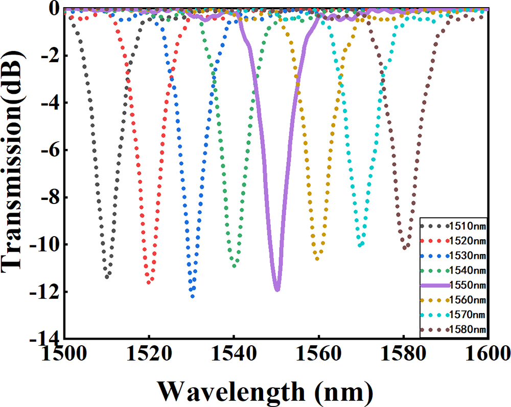
The frequency and amplitude of the acoustic wave generated by the PZT can be controlled by adjusting the frequency and voltage output by the RF signal generator. As the broadband spectrum passes through the AOMC, different wavelengths of light resonate in the AOMC. When the optical beam of the resonant wavelength passes through the SMF, the acousto-optic filtering spectrum can be observed in the optical spectrum analyzer (OSA, Yokogawa-AQ6370D). Figure 1 shows the acousto-optic filtering spectra with a wavelength range of 1510 nm to 1580 nm and a step length of 10 nm. As the frequency of the acoustic wave increases, the resonance wavelength moves to the long wavelength direction, and the acoustic wave frequency has a linear relationship with the resonance wavelength. When the frequency of the RF signal generator is 720.8 kHz, and the output voltage is 20Vpp, the coupling efficiency at 1550 nm can reach 12 dB, and the 3 dB bandwidth of mode conversion is 10 nm. Using a charge-coupled device (CCD, InGaAs-320) camera, the output optical field distributions corresponding to the acousto-optic filter spectrum are detected, and the mode purity can reach 90%. The switching time of different resonance wavelengths is determined by the time for the bending acoustic wave to pass through the acousto-optic coupling region.
![]()
Figure 1.Acousto-optic filtering spectra at different wavelengths.
FM-FBG has three reflection peaks from short to long wavelength: the self-coupling peak of the mode, the mutual coupling peak of the and modes, and the self-coupling peak of the mode. When the broadband optical wave of the mode is incident on the FM-FBG, both the reflected and transmitted wavelengths are located at the self-coupling reflection peak of the mode. Conversely, when the mode light is incident on the FM-FBG, both the reflected and transmitted wavelengths correspond to the self-coupling reflection peak of the mode. Because the FM-FBG is cascaded with an AOMC driven by acoustic wave frequency, different reflected and transmitted peaks corresponding to different modes of the FM-FBG can be controllable through adjusting the frequency of the applied RF signal.
Figures 2(a) and 2(b) show the reflection spectra of the FM-FBG under different acoustic frequencies of the AOMC. Figure 2(a) is the FM-FBG reflection spectrum when the acoustic frequency is 620.8 kHz (non-resonant frequency), and the voltage is 20Vpp. When the acoustic wave frequency is 620.8 kHz, the AOMC staggers mode conversion near the 1550 nm band. It means the unconverted mode enters the FM-FBG. Thus, in the FM-FBG reflection spectrum, the mode self-coupling peak accounts for the highest energy. At the same time, a small portion of the mode transmits through the FM-FBG. When the acoustic wave frequency is switched to 720.8 kHz, and the voltage remains unchanged, the mode self-coupling peak accounts for the highest energy in the FM-FBG reflection spectrum, as shown in Fig. 2(b). Meanwhile, the fraction of the optical field transmitted through the FM-FBG is also the mode. Due to the change of acoustic wave frequency, the reflection spectrum of the FM-FBG switches from the dominant self-coupling peak of the mode to the dominant self-coupling peak of the mode, accompanied by the transmitted optical field switching from the mode to the mode.
![]()
Figure 2.Reflection spectra of the FM-FBG under (a) acousto-optic non-resonance and (b) acousto-optic resonance; the laser output spectra in the CW state under (c) acousto-optic non-resonance and (d) acousto-optic resonance.
![]()
Figure 3.Schematic diagram of mode-field switchable narrow linewidth mode-locked fiber laser. WDM, wavelength-division multiplexer; Cir, fiber circulator; PC, polarization controller; MS, mode stripper; RF, radio frequency generator; SESAM, semiconductor saturable absorber mirror.
Mode-field switchable narrow linewidth mode-locked fiber lasers have important significance in MDM and WDM and are also a good platform for studying the dynamics of a laser cavity. Figure 3 is a schematic diagram of the mode-locked fiber laser possessing the capability of simultaneous wavelength and mode switching. The laser resonator is a ring cavity composed of an SMF and a small part of a TMF participating in mode conversion. The total length of the fiber laser cavity is 15.8 m, and the SMF length is 14 m. There are two optical circulators in the cavity. Optical circulator 1 is connected with the AOMC and FM-FBG cascading structure, and circulator 2 is connected with the SESAM. The 980 nm laser diode (LD) provides pump energy for the laser cavity through a 980/1550 nm WDM. The 1.4 m long erbium-doped fiber (EDF) provides gain for the laser, and its dispersion parameter is . The mode stripper (MS) is used to make the pure fundamental mode of the 1550 nm band enter the AOMC to complete the mode conversion. Polarization controller (PC) 1 is used to adjust the polarization state of the mode when entering the AOMC. The RF signal generator (RIGOL-DG1022) can adjust the frequency and amplitude of the acoustic wave generated by the PZT. PC 2 is used to adjust the intracavity polarization and optimize the mode-locked state of the laser. The modulation depth and relaxation time of the used SESAM are 2.4% and 4 ps, respectively. Its main function is to form soliton pulses and reflect energy back into the cavity. The working wavelength and temporal pulses of the laser out are to be observed from output 1. Output 2 is fixed on the collimator, and the CCD camera is aligned with the collimator to observe the change of the FM-FBG transmitted optical field.
When the pump power is higher than the laser threshold power and lower than the mode-locking threshold power, the laser output is continuous wave (CW). Figures 2(c) and 2(d) show the output spectra of output 1 when the pump power is 200 mW. When the acoustic frequency is non-resonant frequency (620.8 kHz), the spectrum detected by the OSA from output 1 is shown in Fig. 2(c). The center wavelength is 1551.52 nm, the 3 dB bandwidth is 0.018 nm, and the FM-FBG transmission spot is the mode. At the resonance frequency (720.8 kHz), the center wavelength becomes 1550.13 nm, and the 3 dB bandwidth is 0.037 nm, as shown in Fig. 2(d). The FM-FBG transmitted optical spot becomes the mode. The center wavelength of the laser spectrum has shifted from long wavelength to short wavelength by 1.39 nm, and the spectrum is broadened by 0.02 nm. Both laser spectra are within the range of the FM-FBG reflection spectrum. In fiber circulator 1, the forward light of port 2 interferes with the backward light reflected by the FM-FBG. When the light enters the interference field, spectrum filtering is induced, which leads to the narrowing of the linewidth of the outgoing laser. Some high-order modes reflected by the FM-FBG are not completely converted in the AOMC; they are dissipated in the SMF, resulting in a reduction in spectral energy.
When the pump power is higher than 257 mW, by slightly adjusting PC 1 and PC 2 in the laser cavity, the laser under the non-resonant acoustic wave first reaches the mode-locked state. As the pump power is increased to 310 mW, the laser under the resonant acoustic wave reaches the mode-locked state. Under the pump power of 310 mW, the mode-locked spectrum measured by the OSA from output 1 is shown in Fig. 4. The center wavelength of the spectrum is 1551.52 nm, and the 3 dB bandwidth is 0.056 nm. The pulse sequence measured by the oscilloscope (OSC, RIGOL-DS4054) is shown in Fig. 5(a), and the pulse interval is 78.857 ns. Figure 5(b) shows the RF spectrum measured with 1 Hz resolution bandwidth (RBW) in the 100 Hz frequency range, and the signal-to-noise ratio (SNR) is 77.27 dB. The inset in Fig. 5(b) illustrates the RF spectrum in the 0–2 GHz range. The pulse repetition frequency is 12.68 MHz, which is consistent with the theoretical calculation result of the cavity length. At this time, the CCD detected field in the output 2 port is the mode.
![]()
Figure 4.Mode-locked output spectrum under the non-resonant state.
![]()
Figure 5.(a) Mode-locked pulse sequence under the non-resonant state and (b) the corresponding RF spectrum within the frequency range of 100 Hz, with the RBW of 1 Hz (inset: RF spectrum in the 2 GHz range).
With the pump power remaining unchanged, the acoustic wave frequency is adjusted to 720.8 kHz. By adjusting the PC, the laser switches to a new mode-locked state. The center wavelength of the spectrum changes from 1551.52 nm to 1550.21 nm, and the 3 dB bandwidth becomes 0.11 nm, as shown in Fig. 6. The pulse sequence interval becomes 78.86 ns, and the SNR of the RF spectrum is measured to be 75.69 dB with the RBW of 1 Hz, as shown in Fig. 7. The inset in Fig. 7(b) illustrates the RF spectrum in the 0–2 GHz range. The observed field in the CCD shows that the mode is output from the output 2 port. The maximum output powers under available pump power are 3.4 mW and 1.5 mW for non-resonant and resonant cases, respectively.
![]()
Figure 6.Mode-locked spectrum under the resonant state.
![]()
Figure 7.(a) Mode-locked pulse sequence under the resonant state and (b) the corresponding RF spectrum within the frequency range of 100 Hz, with the RBW of 1 Hz (inset: RF spectrum in the 2 GHz range).
Compared with the CW state, the output spectral bandwidth of the fiber laser in the mode-locked state becomes wider, and the transmission field of the FM-FBG becomes more stable. The CW laser spectrum is smooth, and the mode-locked laser spectrum has sideband. The multi-peak structure of mode-locked spectrum may be caused by the filtering effect due to the change of the polarization state. The dynamic adjustment mode in the mode-locked ring cavity has little effect on the pulse repetition rate.
In the mode-locked fiber laser, the FM-FBG not only plays the role of mode selection, but also plays the role of spectrum filtering. The balance of the narrowband filtering effect, self-phase modulation effect, and saturation effect in the laser cavity is of great significance to the formation of narrowband solitons[
By adding a PC to the output port of the FM-FBG and changing the optical path of each degenerate mode in the module, CVBs with different polarization states can be obtained. A spatial light linear polarizer is added between the CCD camera and the output 2 port collimator to adjust the polarization direction of the CVBs. The detected optical field distributions of RPL and APL in different linear polarization directions are shown in Fig. 8. Figures 8(a) and 8(b) are optical intensity distributions of RPL and APL, respectively. Figures 8(c)–8(f) and 8(g)–8(j) are the optical field distributions of RPL and APL in different linear polarization states, respectively. Through the comparison of field energy, the purity of the RPL mode is 94.8%, and the purity of the APL mode is 91.5%.
![]()
Figure 8.Optical intensity distribution of output 2 under the resonant state.
3. Conclusion
In summary, we have realized the switching of the output wavelength and mode field in the passive mode-locked fiber laser through the acousto-optic interaction in the optical fiber. The combination of the AOMC and FM-FBG accounts for the mode field switching by controlling the frequency of acoustic waves and narrow linewidth filtering. The narrow linewidth mode-locked fiber laser with switchable wavelength and mode field has broad prospects in optical fiber communication and sensor systems.
References
[1] A. K. Memon, K. X. Chen. Recent advances in mode converters for a mode division multiplex transmission system. Opto-Electron. Rev., 29, 13(2021).
[2] M. Nakazawa. Exabit optical communication explored using 3M scheme. Jpn. J. Appl. Phys., 53, 08MA01(2014).
[3] R. I. Sabitu, N. G. Khan, A. Malekmohammadi. Recent progress in optical devices for mode division multiplex transmission system. Opto-Electron. Rev., 27, 252(2019).
[4] J. Du, W. Shen, J. Liu, Y. Chen, X. Chen, Z. He. Mode division multiplexing: from photonic integration to optical fiber transmission [Invited]. Chin. Opt. Lett., 19, 091301(2021).
[5] B. Ndagano, R. Brüning, M. McLaren, M. Duparré, A. Forbes. Fiber propagation of vector modes. Opt. Express, 23, 17330(2015).
[6] Q. Zhan. Trapping metallic Rayleigh particles with radial polarization. Opt. Express, 12, 3377(2004).
[7] D. P. Biss, T. G. Brown. Polarization-vortex-driven second-harmonic generation. Opt. Lett., 28, 923(2003).
[8] C. Min, Z. Shen, J. Shen, Y. Zhang, H. Fang, G. Yuan, L. Du, S. Zhu, T. Lei, X. Yuan. Focused plasmonic trapping of metallic particles. Nat. Commun., 4, 2891(2013).
[9] R. Drevinskas, J. Zhang, M. Beresna, M. Gecevičius, A. G. Kazanskii, Y. P. Svirko, P. G. Kazansky. Laser material processing with tightly focused cylindrical vector beams. Appl. Phys. Lett., 108, 221107(2016).
[10] S. Ge, P. Chen, Z. Shen, W. Sun, X. Wang, W. Hu, Y. Zhang, Y. Lu. Terahertz vortex beam generator based on a photopatterned large birefringence liquid crystal. Opt. Express, 25, 12349(2017).
[11] G. Machavariani, Y. Lumer, I. Moshe, A. Meir, S. Jackel. Spatially-variable retardation plate for efficient generation of radially- and azimuthally- polarized beams. Opt. Commun., 281, 732(2008).
[12] A. Arbabi, Y. Horie, M. Bagheri, A. Faraon. Dielectric metasurfaces for complete control of phase and polarization with subwavelength spatial resolution and high transmission. Nat. Nanotechnol., 10, 937(2015).
[13] H. Chen, J. Hao, B. Zhang, J. Xu, J. Ding, H. Wang. Generation of vector beam with space-variant distribution of both polarization and phase. Opt. Lett., 36, 3179(2011).
[14] G. Wang, Y. Li, X. Shan, Y. Miao, X. Gao. Hermite–Gaussian beams with sinusoidal vortex phase modulation. Chin. Opt. Lett., 18, 042601(2020).
[15] T. Grosjean, D. Courjon, M. Spajer. An all-fiber device for generating radially and other polarized light beams. Opt. Commun., 203, 1(2002).
[16] H. Wan, J. Wang, Z. Zhang, Y. Cai, B. Sun, L. Zhang. High efficiency mode-locked cylindrical vector beam fiber laser based on a mode selective coupler. Opt. Express, 25, 11444(2017).
[17] Y. Cai, J. Wang, J. Zhang, H. Wan, Z. Zhang, L. Zhang. Generation of cylindrical vector beams in a mode-locked fiber laser using a mode-selective coupler. Chin. Opt. Lett., 16, 010602(2018).
[18] S. Li, Q. Mo, X. Hu, C. Du, J. Wang. Controllable all-fiber orbital angular momentum mode converter. Opt. Lett., 40, 4376(2015).
[19] Y. Zhao, Y. Liu, C. Zhang, L. Zhang, G. Zheng, C. Mou, J. Wen, T. Wang. All-fiber mode converter based on long-period fiber gratings written in few-mode fiber. Opt. Lett., 42, 4708(2017).
[20] B. Y. Kim, H. E. Engan, H. J. Shaw, J. N. Blake. All-fiber acousto-optic frequency shifter. Opt. Lett., 11, 389(1986).
[21] W. Zhang, K. Wei, L. Huang, D. Mao, B. Jiang, F. Gao, G. Zhang, T. Mei, J. Zhao. Optical vortex generation with wavelength tunability based on an acoustically-induced fiber grating. Opt. Express, 24, 19278(2016).
[22] Q. Gao, Y. Du, Z. He, D. Mao, J. Zhao. Narrowband mode-locked fiber laser via spectral-domain intermodal interference. J. Lightwave Technol., 39, 6276(2021).

Set citation alerts for the article
Please enter your email address
© Copyright 2018-2021 | Chinese Laser Press. All Rights Reserved 沪ICP备15018463号-20