The need for high-speed imaging in applications such as biomedicine, surveillance, and consumer electronics has called for new developments of imaging systems. While the industrial effort continuously pushes the advance of silicon focal plane array image sensors, imaging through a single-pixel detector has gained significant interest thanks to the development of computational algorithms. Here, we present a new imaging modality, deep compressed imaging via optimized-pattern scanning, which can significantly increase the acquisition speed for a single-detector-based imaging system. We project and scan an illumination pattern across the object and collect the sampling signal with a single-pixel detector. We develop an innovative end-to-end optimized auto-encoder, using a deep neural network and compressed sensing algorithm, to optimize the illumination pattern, which allows us to reconstruct faithfully the image from a small number of measurements, with a high frame rate. Compared with the conventional switching-mask-based single-pixel camera and point-scanning imaging systems, our method achieves a much higher imaging speed, while retaining a similar imaging quality. We experimentally validated this imaging modality in the settings of both continuous-wave illumination and pulsed light illumination and showed high-quality image reconstructions with a high compressed sampling rate. This new compressed sensing modality could be widely applied in different imaging systems, enabling new applications that require high imaging speeds.
1. INTRODUCTION
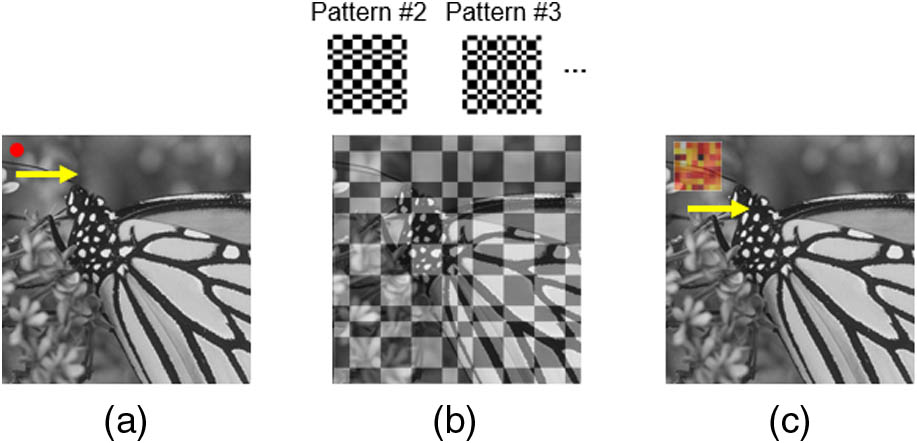
Figure 1.Landscape of imaging methods using a single-pixel detector. (a) Point scanning system where the signal from an individual pixel is sequentially recorded. (b) A conventional single-pixel camera where different patterns are sequentially projected on the entire object, and the overlap integrals between the object and each pattern are measured. (c) Deep compressed imaging via optimized pattern scanning (DeCIOPS), where a pattern is scanned across the object, and the subsampled convolution between the pattern and the object is measured.
In this paper, we propose and demonstrate a deep compressed sensing modality, which can significantly increase the imaging speed while preserving a high reconstruction quality. This approach combines the strength of both compressed sensing and point-scanning imaging, and we call it deep compressed imaging via optimized pattern scanning (DeCIOPS). Instead of projecting multiple binary patterns onto the entire object sequentially, we utilize only one gray-scale optimized pattern and project it to a small subset of the object. We then scan the pattern across the object by using fast scanning mirrors and collect the signal convolutionally using a single-pixel detector [Fig. 1(c)]. Compared with the conventional single-pixel camera, which relies on sequentially switching the sampling pattern on a DMD, our scanning approach significantly increases the sampling speed. Compared with the point-scanning system, our method samples a much larger portion of the object at once and recovers the resolution computationally. This allows a great reduction of the sampling number and thus increases the frame rate. We note that the improvement of imaging speed does not require an increase of light energy. In fact, the required light dosage in our method is smaller than in the conventional point-scanning system due to a reduced number of measurements. We build an auto-encoder framework [17] to optimize the sampling pattern. The image acquisition system is treated as an encoder, where the high-resolution object is encoded through the sampling pattern into a few measurements. We then formulate an iterative shrinkage-thresholding algorithm network (ISTA-Net) [18], a CS-induced neural network inspired by the iterative shrinkage-thresholding algorithm (ISTA) [19], as a decoder to reconstruct the image. This auto-encoder is trained in an end-to-end fashion. Such a framework can learn an optimized sampling pattern and simultaneously recover a high-resolution image by extracting the feature of sparsity and searching the optimal pair of the encoder and decoder with the lowest incoherence [11], which is one key feature of DeCIOPS versus other compressed sensing or deep-learning-based super-resolution imaging modalities [20–23]. This new imaging modality can be accustomed to any light-scanning imaging system and will greatly benefit the high-throughput imaging applications.
This paper is organized as follows. In Section 2, we introduce the mechanisms of the imaging modality in two configurations of illuminations, continuous-wave (CW) and pulsed light source, as well as the auto-encoder framework and the deep compressed sensing neural network for optimizing the imaging and reconstruction. In Sections 3 and 4, we show the simulation results and experimental results. In Section 5, we discuss the system performance under different signal-to-noise ratio (SNR) and compression ratio and how DeCIOPS can be applied in two-photon microscopy and passive lighting conditions.
2. PRINCIPLE
A. Image Formation
Figure 2.Schematic of the undersampling schemes in DeCIOPS. (a) Conventional pixel-by-pixel point scanning. (b) Pixel-by-pixel point scanning with a simple undersampling scheme. (c) DeCIOPS in a CW light source configuration with an illumination pattern of a uniform mask (left) or an optimized mask (right). (d) DeCIOPS in a low-repetition-rate pulsed light source configuration with a uniform mask (left) or an optimized mask (right) as an illumination pattern. The mathematic formula below each panel illustrates the process of image formation, where and are both square shaped.
Mathematically, in low-repetition-rate pulsed light illumination, the image formation of DeCIOPS can be expressed as where is the object, is a square-shaped illumination pattern, represents the 2D convolution, models the undersampling, and is the measured image. Here, we assume that the mask has a size of pixels. In the particular case where is uniform mask [Fig. 2(d), left], Eq. (1) is equivalent to a naïve undersampling by unweighted averaging of every pixels of the full resolution image [Fig. 2(a)] acquired in single-point scanning. As discussed in Section 2.B, can be optimized to achieve the best image reconstruction performance [Fig. 2(d), right].
Sign up for Photonics Research TOC. Get the latest issue of Photonics Research delivered right to you!Sign up now
In the CW light or high-repetition-rate pulsed light illumination case, where the detector continuously integrates the signal, we configure the illumination pattern in a size of pixels. When this pattern sweeps columns, the information of pixels is integrated into a single measurement [Fig. 2(c)]. We can use the same mathematical formulation as Eq. (1) to model the image formation, where each column in the mask is identical.
B. End-to-End Optimized Auto-Encoder Framework
Figure 3.End-to-end optimized auto-encoder framework of image formation and reconstruction in DeCIOPS. The encoder models the image formation. It encodes the high-resolution (HR) object into a low-resolution (LR) output through subsampled convolution and additive noise. The decoder is implemented with an ISTA-Net, which contains N phases and reconstructs the object . Each phase is realized by a structure-symmetric pair of a forward transform and a backward transform with a soft shrinkage threshold, which factually matches one iteration in the conventional ISTA. ReLU, rectified linear unit; , soft shrinkage threshold.
The decoder takes as the input and aims to reconstruct the original object by solving the following convex optimization problem with a constraint of the sparse representation of : where denotes a transform of into a sparse representation under the basis of , and is a hyperparameter.
The solution of the problem in Eq. (3) can be initialized by calculating the pseudo-inverse of the encoder from the measurement . We then use ISTA [19] to find an optimized solution of by iterating the following two steps: where denotes the kth ISTA iteration step, and is the step size.
As is predefined empirically and may not be suitable for the data, we adopt the ISTA-Net algorithm [18], which can learn through the data. In ISTA-Net, is replaced with a trainable neural network , and the optimization problem in Eq. (3) can be rephrased into the following L1-norm regularization problem with a nonlinear transform :
The th iteration step in the original ISTA is replaced by a series of symmetric learnable parameters in the th ISTA-Net phase: where is a learnable parameter in the th module, is the inverse of , and represents the soft shrinkage threshold. Finally, we obtain the output of the decoder after a total number of ISTA-Net phases.
The loss function of ISTA-Net is obtained by calculating the mean square error (MSE) between the output and the ground truth with the constraint of , as both and are learnable and symmetric, where is the identity operator. As a result, we have the following loss function with the symmetry constraint: where is the weight of the symmetry constraint.
3. SIMULATION RESULTS
We trained the auto-encoder using 1500 samples of natural scenes (2D gray-scale image, pixel size) from ImageNet [24] and validated the model with 79 samples from two widely used benchmark datasets: Set11 [25] and BSD68 [26]. As an illustration, we chose an undersampling rate of 6.25% ( undersampling) and initialized the pattern as a normalized random Gaussian matrix. was set to be 0.01 in the loss function, accompanied by Adam optimization with a learning rate of . We included additive noises in the measurement (5%–10% of the signal strength). The training was performed on a GPU RTX2080Ti 11 GB. The training work of ISTA-Net phases takes for 200 epochs with a batch size of five. We trained two independent auto-encoders, one with a constraint on so each column of is identical (CW light or high-repetition-rate pulsed light illumination) and one without such a constraint (low-repetition-rate pulsed light illumination). The reconstruction results are evaluated in terms of peak signal-to-noise ratio (PSNR) and spatial resolution by using Fourier ring correlation [27] in the validation dataset. As a control measure, we compared the reconstruction performance of the optimized pattern [Figs. 2(c)and 2(d), right] with a random pattern and two naïve undersampling schemes of the full resolution image either through an unweighted averaging of pixels [equivalent to the uniform pattern, Figs. 2(c) and 2(d), left] or a simple dropout [i.e., pick one pixel in every and drop out the others, Fig. 2(b)]. All of the simulation groups employ an independently trained ISTA-Net for image reconstruction. In addition, we also used B-spline interpolation [28] to reconstruct the image that was undersampled through a simple dropout.
Figure 4.Comparison of the reconstruction performance in the validation data set Set11 and BSD68, at an undersampling rate of 6.25%, through (a) a simple dropout, (b) an unweighted average (uniform pattern), (c) a random or an optimized illumination pattern (DeCIOPS) with a constraint of identical column, and (d) a random or an optimized illumination pattern (DeCIOPS). The PSNR and resolution of the reconstructed images are labeled below the exemplary sample. (e) PSNR of the reconstructed images of all 79 samples in the validation dataset for cases in (a)–(d). (f) Resolution of the reconstructed images of all 79 samples in the validation dataset for cases in (a)–(d). n.s., not significant; *, ; **, ; ***, ; ****, , in one-way analysis of variance (ANOVA).
Figure 5.Experiment setup of DeCIOPS. The laser beam is spatially filtered to improve its spatial uniformity and symmetricity, collimated and expanded in size, and then incident onto a DMD. The beam is spatially modulated by the DMD and then shrunk in size by a system formed by a tube lens and an objective lens. The light pattern is scanned by a resonant-galvo scanner set, where a resonant scanner and a galvanometer mirror are optically coupled through a relay lens set. The transmitted light from the sample is collected by a photodetector through a collection lens. The pattern is generated by the DMD. With an additional system with cylindrical lenses after the objective lens, the pattern can be turned into size (Appendix A.1). The red dashed line (plane 1 and object plane) indicates the conjugate plane of the gray-scale pattern mask.
As the optical mode from the diode laser did not have uniform intensity, and the pattern could be corrupted by laser interference, we calibrated the DMD to ensure the illumination pattern on the sample plane matched well with the design (Appendix A.3). While our imaging system is naturally a CW light imaging system, we could also mimic the pulsed light source condition through an additional digital sampling step after the image acquisition (Appendix A.5).
A. Reconstruction Results with a CW Light Source
Figure 6.Comparison of the experimental results using different illumination patterns in the scanning in a CW illumination setting. (a)–(d) Experimental results of the sample: (a) butterfly, (b) cameraman, (c) house, and (d) the Flintstones. The different columns show the ground truth results using high-resolution point scanning, raw measurement using different illumination patterns at an undersampling rate of 6.25%, and the corresponding reconstruction results. (e) PSNR of the reconstructed images for a total of nine samples. (f) Spatial resolution of the reconstructed images for a total of nine samples, calculated from Fourier ring correlation. *, ; **, ; ***, ; ****, , in one-way ANOVA.
B. Reconstruction Results with a Low-Repetition-Rate Pulsed Light Source
Figure 7.Comparison of the experimental results using different illumination patterns in the scanning in the low-repetition-rate pulsed light illumination setting. (a)–(d) Experimental results of the sample: (a) butterfly, (b) cameraman, (c) house, and (d) the Flintstones. The different columns show the ground truth results using high-resolution point scanning, raw measurement using different illumination patterns at an undersampling rate of 6.25%, and the corresponding reconstruction results. (e) PSNR of the reconstructed images for a total of nine samples. (f) Spatial resolution of the reconstructed images for a total of nine samples, calculated from Fourier ring correlation. *, ; **, ; ***, ; ****, , in one-way ANOVA.
Figure 8.(a) PSNR and (b) pixel resolution of the reconstructed images versus different SNRs in the raw measurement, for three different sampling patterns (CW configuration), performed through simulation at an undersampling rate of 6.25%. The results were averaged across nine samples used in the experiment and fitted with polynomial curves. (c) and (d) show the experimental results averaged across nine samples.
B. Compressed Ratio and Size of the Optimized Pattern
Figure 9.DeCIOPS reconstruction quality (a) PSNR and (b) pixel resolution dependence on the size of the optimized pattern, for an undersampling rate of 25% (, red), 11.1% (, green), 6.25% (, blue), and 1.5625% (, black), across all 79 samples in the validation dataset. Solid curve, mean; shaded area, standard deviation.
In the conventional switching-mask-based single-pixel camera, the random mask is one of the commonly used sampling bases, as it is incoherent with the spatial property of the sample. We found the same in the pattern-scanning scheme: the random pattern shows a superior performance compared with the uniform pattern. However, the optimized pattern, found by the auto-encoder through the end-to-end optimization, outperforms the random pattern. This is expected, as the random pattern attained by the Monte Carlo method is independent of the dataset of a specific task, unlike the optimized pattern. Furthermore, the performance improvement of the optimized pattern over the random pattern increases when the measurements are more highly undersampled, as seen in the comparison between 6.25% ( pattern) and 1.5625% ( pattern) (Table 1). This is attributed to more trainable parameters in the case of the optimized pattern and more uncertain random variables in the case of the random pattern.
Comparison of the PSNR and Pixel Resolution across the Uniform Pattern, Random Pattern, and Optimized Pattern between 6.25% and 1.5625% Undersampling Rate in DeCIOPSa
Undersampling Rate
PSNR (dB)
Normalized Resolution (pixel)
Uniform Pattern
Random Pattern
Optimized Pattern
Uniform Pattern
Random Pattern
Optimized Pattern
6.25%
1.5625%
CW light configuration, , for all 79 samples in validation dataset.
D. Comparison with Conventional Switching-Mask-Based Single-Pixel Camera
Figure 10.Comparison of the reconstruction results between DeCIOPS and conventional switching-mask-based single-pixel camera. (a) The ground truth of an original object, butterfly. (b) Reconstruction result of DeCIOPS using ISTA-Net at an undersampling rate of 6.25%. (c) Reconstruction result of the switching-mask-based single-pixel camera imaging approach using ISTA-Net. Top row, simulation. Bottom row, experiment. The ground truth of the experiment is obtained by the high-resolution point scanning.
In DeCIOPS, we apply ISTA-Net as the decoder. ISTA-Net is a CS-induced neural network. Compared with conventional optimization algorithms where the regularization term is designed empirically, ISTA-Net is entirely data-driven and can learn optimized regularization through the neural network. Compared with other neural networks that could be used for super-resolution, such as U-Net [30,31] and densely connected super-resolution network (DCSRN) [32,33], the embedded CS algorithm in ISTA-Net fits better in the motivation of DeCIOPS and other compressed sensing framework, i.e., performing fewer measurements while being able to reconstruct high-resolution images. Indeed, when we compare the PSNR and pixel resolution of the reconstructed images across ISTA-Net, U-Net, and DCSRN, ISTA-Net shows the best performance (Appendix B). In addition to DeCIOPS, we believe ISTA-Net could also benefit other applications such as denoising [34], fast magnetic resonance imaging (MRI) [35], and other super-resolution imaging modalities [18].
F. Advantage of End-to-End Optimized Auto-Encoder and Its Application in Future Imaging Systems
In most existing optical imaging modalities, image formation is empirically designed and optimized, and the deconvolution or object reconstruction algorithm is subsequently tailored to the image formation process. The recent development of low-cost, advanced micro-optics manufacturing techniques, such as three-dimensional (3D) printing and micro–nano-fabrication [36–40], allows rapid prototyping of user-designed optical elements, which opens new opportunities to redesign the image formation process that best fits the specific applications. Instead of sequentially designing the image formation and the reconstruction algorithm, their joint end-to-end optimization produces a global optimal solution [41–43], which is the underlying principle of DeCIOPS. We use an auto-encoder to model the image formation and reconstruction within a single framework and perform end-to-end training to optimize the sampling pattern and ISTA-Net simultaneously. Our results show that the optimized sampling pattern indeed results in the best overall performance. Such an end-to-end training and data-driven approach prevents any empirical bias that may negatively impact the design. We envision that such an approach will enable many challenging applications such as super-resolution imaging [23,42–46], 3D imaging [41,47–49], and high-speed computational cameras [50–52].
G. Applicability in Two-Photon Microscopy
While our imaging system used a CW light source, we mimicked the experimental condition of a pulsed light source and successfully demonstrated the applicability and excellent performance of DeCIOPS. This opens a new avenue to apply DeCIOPS in two-photon microscopy. In conventional two-photon microscopes [5,7,8], the image is acquired through pixel-by-pixel point scanning. While this enables deep tissue imaging as it resists light scattering, it reduces the imaging speed. Recently, there have been multiple reports applying compressed sensing in two-photon microscopy, with the same approach in the conventional switching-mask-based single-pixel camera [53–55]. However, the improvement on the imaging speed is limited due to the low switching speed of DMDs or the liquid-crystal-based spatial light modulators. When applying DeCIOPS in two-photon microscopy, we expect that our approach will significantly increase the imaging speed and will notably benefit functional imaging through two-photon microscopy.
H. Passive Light Illumination
In our experiment, DeCIOPS is implemented using active light illumination (i.e., structured illumination), which is commonly used in biomedical imaging. In other imaging systems, passive light illumination may be preferred. In fact, any passive light illumination wide-field imaging using a focal plane array (i.e., camera) can be converted to DeCIOPS (Appendix C). A scanner can be added to the passive wide-field imaging to scan the entire image originally projected to the camera. By inserting a fixed mask with an appropriate aperture at the plane where the image is scanned, a single-pixel detector can measure the subsampled convolution between the mask and the original image. The object can then be reconstructed using the same algorithms in DeCIOPS for the active light illumination cases. This way, a structured detection version of DeCIOPS can be implemented.
6. CONCLUSION
We demonstrated a new high-speed imaging modality, DeCIOPS, by synthesizing the strength of conventional point scanning and single-pixel camera through compressed sensing. The high-speed imaging arises from the fast beam-scanning mechanism and a highly efficient sampling scheme through compressed sensing; meanwhile, an auto-encoder framework allows the simultaneous optimization of the image formation and reconstruction process in DeCIOPS. We validated DeCIOPS through both simulation and experiments in both CW and pulsed light source conditions. This new image modality can be adapted to any existing imaging systems using beam scanning, such as confocal microscope and two-photon microscope, or wide-field cameras with an added scanning system, and will benefit broad applications requiring high-speed imaging.
Appendix A: Experimental Setup of DeCIOPS
Optical Setup
The optical setup of DeCIOPS illustrated in Fig.?5 scans an pattern on the object and is suitable for low-repetition-rate pulsed light illumination settings. For CW light or high-repetition-rate pulsed light illumination, an pattern is scanned. When this pattern sweeps columns, the information of pixels can be integrated into a single measurement. To generate the pattern, we set the column to be identical in the pattern and add a system composed of cylindrical lenses after the objective lens. The pattern is then shrunk in one dimension by a factor of into the pattern (Fig.?11). The parameters of the lenses used in the setup are listed in Table?3.
Figure 11.Experimental setup of DeCIOPS that generates an size pattern and scans it across the sample. The setup is similar to that generating the size pattern shown in Fig. 5, but with a system composed of cylindrical lenses added after the objective lens to shrink the original size pattern in one dimension by a factor of into the size. The red dashed line (plane 1 and object plane) indicates the conjugate plane of the gray-scale pattern mask.
Figure 12.(a) Measured patterns on the sample (super-pixels) match well with the designed patterns. Each gray-scale super-pixel is generated by binary pixels in the DMD. The left panel shows the cases for patterns, and the right panel shows the cases for the pattern. (b) A single spot pattern is generated for conventional point-scanning imaging to obtain the high-resolution ground truth of the sample. The spot size matches the size of a super-pixel. (c) Pixel-by-pixel comparisons between the measured patterns on the sample and the designed patterns show excellent matchings between the two.
Data acquisition is performed using a high-speed data acquisition card vDAQ and ScanImage software (Vidrio Technologies). As the illumination pattern continuously scans across each row, the data acquisition card samples the data from the photodetector at a rate higher than the single-pixel rate. The data acquired within the duration of a single pixel is then automatically averaged/integrated and saved as a single-pixel value. Compared with the full resolution single-point-scanning condition ( pixels), we reduce the single-pixel rate and the number of scanning lines by 75% in DeCIOPS (CW light setting), reaching an undersampling rate of 6.25% ( pixels of measurement).
To mimic the low-repetition-rate pulsed light source condition, we sample the object with a high resolution at pixels (corresponding to a high single-pixel rate) and then downsample the acquired image digitally into pixels by dropping all of the other pixels. Here, each pixel has a small average/integration duration and could thus be considered as being acquired by a single light pulse.
Estimation of Signal-to-Noise Ratio
To calculate the SNR of the image in the experiment, we acquire the same image 20 times. For each pixel, we calculate the signal and the noise as the mean and the standard deviation across 20 measurements, respectively. The SNR for the pixel is then estimated as . The SNR of the entire image is taken as the average of the SNR of all pixels.
Appendix B: Comparison between ISTA-Net, U-Net, and DCSRN
We compare the performance of ISTA-Net, U-Net, and DCSRN in object reconstruction. In the auto-encoder framework, the decoder implemented by ISTA-Net is replaced by U-Net or DCSRN. U-Net is widely used in image reconstruction and segmentation. It first condenses the size of the input images to extract its context and feature and then grows them in an expanding path to perform local reconstruction [30]. DCSRN, derived from densely connected convolutional networks [33], has a faster training speed and accurate reconstruction results and is commonly used in applications such as 2D or 3D biomedical super-resolution imaging. In addition to ISTA-Net, U-Net, and DCSRN, we used B-spline interpolation [28] to reconstruct the object undersampled through a simple dropout as a baseline. All of the simulation was completed on GPU RTX1080Ti 11?GB with 200 epochs and a batch size of five. In each decoder except for the B-spline, we learned an optimized illumination pattern. We used the validation data set to evaluate the PSNR and pixel resolution of the reconstructed objects. U-Net, DCSRN, and ISTA-Net all outperform B-spline interpolation. While U-Net and DCSRN do not show a significant difference in performance, ISTA-Net outperforms both U-Net and DCSRN with a increase in PSNR and 6.55% improvement in resolution at an undersampling rate of 6.25% (Fig.?14). The simulation results demonstrated a clear advantage of ISTA-Net, which is a CS inspired neural network, in DeCIOPS.
Figure 14.Comparison of (a) PSNR and (b) pixel resolution of the reconstructed objects of all 79 samples in the validation dataset for B-spline, U-Net, DCSRN, and ISTA-Net in the auto-encoder framework, at an undersampling rate of 6.25%. n.s., not significant; **, ; ***, ; ****, , in one-way ANOVA.
Appendix C: DeCIOPS Using Passive Light Illumination
To implement DeCIOPS in a passive light illumination setting (i.e., structured detection), which is commonly used in photography, a scanner can be added to the passive wide-field imaging system to scan the entire image originally projected to the camera. By inserting a fixed mask with an appropriate aperture at the plane where the image is scanned, a single-pixel detector can measure the subsampled convolution between the mask and the original image (Fig.?15). The object can then be reconstructed using the same algorithms in DeCIOPS for the active light illumination cases.
Figure 15.Optical setup of DeCIOPS with passive light illumination (i.e., structured detection) for applications such as photography.
[17] H. Wu, Z. Zheng, Y. Li, W. Dai, H. Xiong. Compressed sensing via a deep convolutional auto-encoder. IEEE Visual Communications and Image Processing (VCIP), 1-4(2018).
[18] J. Zhang, B. Ghanem. ISTA-Net: interpretable optimization-inspired deep network for image compressive sensing. IEEE Conference on Computer Vision and Pattern Recognition, 1828-1837(2018).
[21] L. Fang, F. Monroe, S. W. Novak, L. Kirk, C. R. Schiavon, S. B. Yu, T. Zhang, M. Wu, K. Kastner, Y. Kubota, Z. Zhang, G. Pekkurnaz, J. Mendenhall, K. Harris, J. Howard, U. Manor. Deep learning-based point-scanning super-resolution imaging(2019).
[24] J. Deng, W. Dong, R. Socher, L.-J. Li, K. Li, L. Fei-Fei. Imagenet: a large-scale hierarchical image database. IEEE Conference on Computer Vision and Pattern Recognition, 248-255(2009).
[25] K. Kulkarni, S. Lohit, P. Turaga, R. Kerviche, A. Ashok. Reconnet: non-iterative reconstruction of images from compressively sensed measurements. IEEE Conference on Computer Vision and Pattern Recognition, 449-458(2016).
[26] D. Martin, C. Fowlkes, D. Tal, J. Malik. A database of human segmented natural images and its application to evaluating segmentation algorithms and measuring ecological statistics. 8th IEEE International Conference on Computer Vision (ICCV), 416-423(2001).
[30] O. Ronneberger, P. Fischer, T. Brox. U-net: convolutional networks for biomedical image segmentation. International Conference on Medical Image Computing and Computer-Assisted Intervention, 234-241(2015).
[32] Y. Chen, Y. Xie, Z. Zhou, F. Shi, A. G. Christodoulou, D. Li. Brain MRI super resolution using 3D deep densely connected neural networks. IEEE 15th International Symposium on Biomedical Imaging (ISBI), 739-742(2018).
[33] G. Huang, Z. Liu, L. Van Der Maaten, K. Q. Weinberger. Densely connected convolutional networks. IEEE Conference on Computer Vision and Pattern Recognition, 4700-4708(2017).
[35] E. D. W. N. Pezzotti, S. Yousefi, M. S. Elmahdy, J. van Gemert, C. Schülke, M. Doneva, T. Nielsen, S. Kastryulin, B. P. F. Lelieveldt, M. J. P. van Osch, M. Staring. Adaptive-CS-Net: FastMRI with adaptive intelligence(2019).
[41] Y. C. Wu, V. Boominathan, H. J. Chen, A. Sankaranarayanan, A. Veeraraghavan. PhaseCam3D-learning phase masks for passive single view depth estimation. IEEE International Conference on Computational Photography(2019).