Key Laboratory of Space Laser Communication and Detection Technology, Shanghai Institute of Optics and Fine Mechanics, Chinese Academy of Sciences, Shanghai 201800, China
We present a tabletop-scale spotlight-mode down-looking synthetic aperture imaging ladar (DL SAIL) demonstrator, which is performed by a collimator with 10 m focal length to simulate the far-field optical field. A specular-point target and a diffuse-reflection target have been used for resolution analysis and 2D imaging, respectively. The experimental result is in agreement with the theoretical design. The experiment setup is capable of simulating a real application scenario for further study. This Letter is focused on the proposition and implementation of spotlight-mode DL SAIL.
The down-looking synthetic aperture imaging ladar (DL SAIL) principle was proposed by Liu[1,2] and experimentally proved by Luan[3]. DL SAIL consists of a transmitter of two coaxial and phase-modulated polarization-orthogonal beams. Based on the projection imaging of beam distributions, the receiver collects the linear phase modulation in the orthogonal direction of travel and quadratic phase modulation in the travel direction. DL SAIL has many operational modes[4] including strip-mode, spotlight-mode, interferometric imaging, and so on.
In recent research, static-mode DL SAIL[5] has been further proposed, which is able to observe a static target with a motionless platform. The DL SAIL achieves fine-resolution, long-distance, and 2D imaging with modest aperture diameters, and has an inherent feature, i.e., the size of the optical footprint together with the associated imaging resolution is controllable and changeable over a large scale. The influence from atmospheric turbulence and unmodeled line-of-sight motion can be automatically compensated.
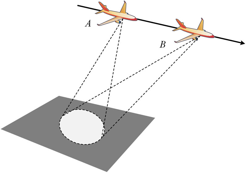
In a real application scenario, strip-mode does not readily meet the requirement for target detection due to high laser power and low receiving energy. In order to improve this, spotlight-mode operation is proposed to enable the transmitter to spotlight the target as long as necessary with the help of a beam scanner, as illustrated in Fig. 1. Extending the spotlight duration and correspondingly reducing the scanning speed in the orthogonal direction of travel, by collecting enough receiving energy and lowering the laser power, can be achieved. Therefore, spotlight-mode DL SAIL is very useful for long-range imaging.
Sign up for Chinese Optics Letters TOC. Get the latest issue of Chinese Optics Letters delivered right to you!Sign up now
We propose a spotlight-mode setup which consists of a transmitter and receiver, the beam scanner, the collimator, and the target translation stage. Thus, this Letter is focused on the proposition and implementation of spotlight-mode DL SAIL. Through the synchronization using in-house software, spotlight-mode DL SAIL can be achieved.
The spotlight-mode DL SAIL imaging measurements were performed using a tabletop-scale setup diagrammed in Fig. 2, showing the basic principle structure of the demonstrator. The transmitter consists of a laser source, a polarization modification of a Mach–Zehnder (MZ) interferometer including two orthogonal direction of travel scanning cylindrical lenses and one travel direction scanning cylindrical lens, a collimator, and a beam scanner. The MZ device is used to split the input laser beam into two beams and then to combine them into one. The V-channel consists of a window, a closely placed -directed (orthogonal direction of travel) cylindrical lens , and a -directed (travel direction) cylindrical lens ; the H-channel consists of a window and a closely placed -directed (orthogonal direction of travel) cylindrical lens . The synchronized shift of and is used to produce linear phase modulation in the orthogonal direction of travel. The is used to produce quadratic phase in the travel direction.
Figure 2.Structure of spotlight-mode DL SAIL demonstrator.
It is noted that the MZ device has two specially designed polarization channels. Each includes a polarization beam splitter (PBS), a wave plate (WP), and a mirror. In combination, the parallel polarization component passes through the PBS directly and the vertical polarization component via the WP, and the mirror is rotated in polarization by 90° and crosses the PBS. It can be understood that this combination delays the vertical polarization component and furthermore reverses its optical field, such that the two windows (V-channel and H-channel) on the same plane. The joint shift of and derived by a linear motor results in a countermove of their phase distributions in the output of the MZ device.
In order to simulate far-field optical distribution in the lab and implement spotlight-mode operation, we assembled a nonspherical collimator as the far-field simulation lens with 10 m focal length and a rotating double-prism wide-angle laser beam scanner as our beam scanner. The aperture is large enough to collect echoed energy. The 10 m focal length can form a proper footprint size together with the 500 mm focal length transmitting lens. The beam scanner can ensure a sufficient scanning angle as well as scanning accuracy. The transmitting lens and collimator project the modulated inner optical field to target the surface with an amplification factor of where Z is the detection range, which is equal with the focal length of collimator, f1 is the focal length of transmitting lens. The beam scanner can control the footprint movement in the travel direction the same as the target translation stage movement direction.
When the imaging system begin to work, the target’s information is mixed with zero frequency, which makes the target’s image unable to distinguish. In order to move the target information out of zero frequency, a nonzero value is essential, which will be discussed in detail in a subsequent paragraph. Term equals the distance of the center between two channels minus the distance of the center between two orthogonal direction of travel cylindrical lenses.
The receiver consists of a receiving telescope, a optical hybrid[6], and balanced amplified photodetectors. The collected data by the balanced amplified photodetectors is acquired by an National Instruments PXIe-6356 data acquisition card and the raw data is stored in a personal computer. The raw data is then processed by the classical focus algorithm.
Synchronization of the target translation stage, beam scanner, orthogonal direction of travel scanning cylindrical lenses, and travel direction cylindrical scanning lens is crucial. If not, the system will transform spotlight-mode into slide spotlight-mode, which will be further discussed in a future paper.
The built demonstrator is shown in Fig. 3. The inner optical field of in the H-channel and V-channel in the MZ device can be described, respectively, by where is the fast time for each orthogonal direction of travel shifting, is the sampling time interval in the orthogonal direction of travel, and are the stop sizes of the inner field, is the equivalent curvature radius of and , is the equivalent curvature radius of , is the scanning speed of the orthogonal direction of travel, is the sampling time width of the travel direction from 0 to , and is the spotlight time.
Figure 3.Open view of built spot-mode DL demonstrator.
By the opposite scanning of the orthogonal direction of travel cylindrical lenses, the phase of the inner optical field is modulated and the difference between the two phases is a time-variant linear phase term. This enables the DL SAIL the use a single-frequency laser source instead of an ultra-broad bandwidth linearized chirp laser in a traditional SAIL system.
The transmitting lens and collimator project the modulated inner optical field to the target surface with an amplification factor of .
The size of the footprint is and , where is the footprint size in the orthogonal direction of travel, and is the footprint size in the direction of travel. The footprint can be easily adjusted to certain applications by changing the focal length of the transmitting lens .
The reflected beam is then rotated 45° by a WP and split into two channels by a optical hybrid. The current output is given by where includes all the factors of the transmission, propagation, and optical-to-electrical conversion; and is the moving speed of the target translation stage, which is equal to the beam scanner’s equivalent speed on the focal plane of the collimator under spotlight-mode operation.
To process the raw data, the 2D data are first focused by a fast Fourier-transform (FFT) algorithm in the orthogonal direction of travel and then focused by the matched filtering in the travel direction, with a conjugate phase of the phase history in the travel direction. We have the 2D focused result where and . The symbol is the 2D convolution operator. The resolution full-width-zero-magtitude (FWZM) in the orthogonal direction of travel is given by The resolution (FWZM) in the travel direction is given by
To enable the system to operate under spotlight-mode, the relationship of the orthogonal direction of travel scanning speed, travel direction scanning speed, target stage speed, and beam scanner’s scanning speed is crucial. They should synchronized under a certain relationship.
The cylindrical wavefront speed in the orthogonal direction of travel is denoted as . Term is a coefficient, is as defined previously, and is the orthogonal direction of travel sampling time during each shifting. The travel direction cylindrical wavefront speed is denoted as . Term is the cylindrical wavefront (travel direction) moving distance on the focal plane of collimator, is as defined previously, and is the spotlight time. Considering the time relationship, and , where is the travel direction sampling number, is the sampling time interval in travel direction, and is a coefficient. We can obtain the relationship of and as
The target translation stage movement distance can be denoted as , where is the target translation stage speed or the beam scanner’s equivalent speed on the focal plane of the collimator. Thus, the relationship of and is
According to Eqs. (6) and (7), we developed in-house software to synchronize the four motors using a stop-and-go assumption. A single frequency laser of 532 nm wavelength is used. The transmitting lens has the focal length of 500 mm and an aperture diameter of 200 mm. Lenses , , and are positive cylindrical lenses and the focal lengths are all 60 mm. Lenses and are located around the focal plane of the transmitting lens and the distance between and is 6.45 mm. The distance between two channels is 8.45 mm. The repeated frequency of shifting of and is 1 Hz. The spot size of the inner field is 1.3 mm. The target translation stage movement distance . From the design, the theoretical imaging resolutions (FWZM) are estimated as for a point target and about for a target as illustrated in Fig. 4.
The 2D imaging ability is then tested using the letter ‘Z’ of size cut from retro-reflective tape as illustrated in Fig. 5. The center imaging frequency is 250.6 Hz and the sampling rate is 1 kHz. Due to the instability of mechanical movement, the final image does not focus very well. To obtain better image quality, we will develop an algorithm to enable the beam scanner to acquire real-time position information and adjust itself to maintain the mechanical stability and conduct quantitative analysis in the next phase of our work.
In conclusion, we propose and implement a spotlight-mode DL SAIL demonstrator, using a 10 m non-spherical collimator and beam scanner with the rotating double-prism. The experimental results are in agreement with the theoretical design. This setup will be tested in out-field and the system parameters can be changed to adapt to the airborne experiment based on the same design principle.