
Shijie Tu, Qiannan Lei, Yangjian Cai, Qian Zhao. Generation of Lommel beams through highly scattering media[J]. Chinese Optics Letters, 2022, 20(9): 092501
- Chinese Optics Letters
- Vol. 20, Issue 9, 092501 (2022)
Abstract
1. Introduction
In recent years, nondiffracting beams have attracted much attention due to their peculiar properties[
When optical beams propagate in materials with inhomogeneous index distributions, they will suffer distortions or scattering. In order to promote the applications of Lommel beams in different materials, the propagation properties of Lommel beams in some aberration-weak media such as gradient index medium[
In this paper, we utilize a digital micromirror device (DMD) to produce Lommel beams through a highly scattering medium by means of a transmission matrix (TM)-based point spread function (PSF) engineering method. All of the experimental results of the constructed Lommel beams agree well with the theoretical predictions. Moreover, the optical field distributions and OAM can be engineered continuously by adjusting the parameters in the angular spectrum. The intensity profiles of the generated beams were recorded, and their phase distributions were measured by the phase shifting method. Furthermore, the raster scanning of Lommel beams was demonstrated, and a number of Lommel beams were constructed simultaneously. The constructed Lommel beams under high scattering could promote the development of optical communication and optical manipulation behind highly scattering media.
Sign up for Chinese Optics Letters TOC. Get the latest issue of Chinese Optics Letters delivered right to you!Sign up now
2. Principle
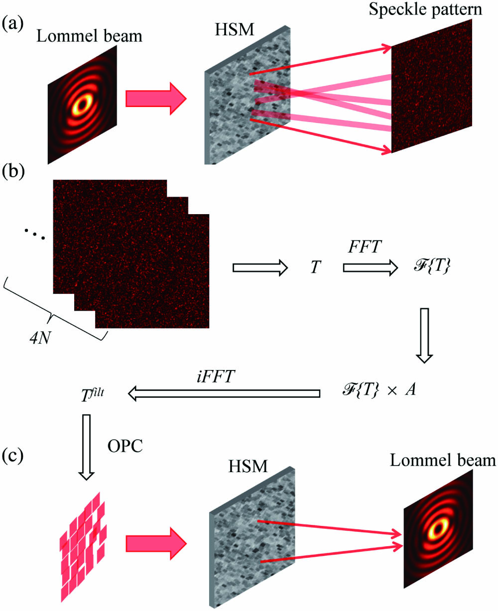
Figure 1 illustrates the principle. As shown in Fig. 1(a), when an optical Lommel beam propagates through a highly scattering medium, the beam occurs with multiple scattering, and the wavefront is scrambled, thus producing a random speckle field distribution behind the highly scattering medium. In this situation, the performance of the Lommel beam is completely suppressed. For the mathematical description, the optical field at the input plane and output plane can be, respectively, set as an vector and an vector, where and are the numbers of the input modes and output modes. Due to the scattering process being linear and deterministic, the relationship between the output field () and input field () can be described as[
![]()
Figure 1.Principle of constructing Lommel beams through highly scattering media with TM-based PSF engineering method. (a) When a Lommel beam is incident on a highly scattering medium (HSM), the transmitted light becomes a speckle field due to multiple scattering. (b) Flow chart of TM-based PSF engineering method. (c) With the calculated wavefront as the input field impinging on this HSM, the desired Lommel beam can be obtained at the output plane behind the HSM. OPC, optical phase conjugation.
For the diffraction-free Lommel beam[
The corresponding Fourier transform of the Lommel beam is expressed as
From Eq. (5), we can see that the angular spectrum of the ideal Lommel beam is an infinitely thin ring due to the existence of . According to Ref. [26], when the thin ring is directly used as a mask for numerical filtering in the method of TM-based PSF engineering, it will remove most of the low frequencies of the input field that contributes to the focus, leading to the generated PSF distribution at the focal plane with a low signal-to-backgound ratio (SBR). Thus, in order to generate Lommel beams with a high SBR, we set the annular mask with a thickness and modify Eq. (5) as
After the complex is constructed, we employed it as a mask to filter the calibrated TM as Eq. (2), and the resulting operator can then be used to compute the complex input field with the operation of optical phase conjugation (OPC). Finally, with the calculated input field impinging on this highly scattering medium, the desired Lommel beam can be produced at the output plane, as shown in Fig. 1(c).
3. Experiment
Figure 2 sketches the experimental setup. To achieve a rapid wavefront shaping, we utilized a high-speed DMD (Vialux V-7001) as a spatial light modulator, which can switch at a rate of 22.727 kHz. A laser beam with (Cobolt 04-01 Series) was expanded by a telescope constituted by L1 and L2 and reflected by M1 to fully illuminate the surface of the DMD. Then, with the assistance of a configuration and a spatial filter, the superpixel method[
![]()
Figure 2.Experimental setup. L, lens; M, mirror; BS, beam splitter; DMD, digital micro-mirror device; F, filter; OBJ, objective lens; HSM, ZnO scattering layer; CMOS, complementary metal-oxide-semiconductor camera.
In order to verify the validity of our method, we first constructed a Lommel beam with , through ZnO scattering layer. The intensity and phase profiles of the desired beam are shown in Figs. 3(a) and 3(b). Its corresponding intensity and phase profiles in the angular spectrum are shown in Figs. 3(c) and 3(d). Note that the outer and inner radii of the annular mask were and pixels of the output plane in order to increase the SBR at the focal plane. Employing this angular spectrum as a filtering mask in the TM-based PSF engineering method, we were able to generate the desired Lommel beam through highly scattering media. Figures 3(e) and 3(f) are the intensity and phase profiles of the generated Lommel beam in simulation. In comparison, the corresponding profiles of the experimentally generated Lommel beam behind the ZnO scattering layer are, respectively, illustrated in Figs. 3(g) and 3(h). In order to make a further comparison among the theoretical distribution, simulation result, and experimental result, their intensity profiles along the white dashed line and the blue dashed line are plotted in Figs. 3(i) and 3(j), respectively. It can be observed that both of the experimental and simulated results agree well with the theoretical distribution. In this case, the Lommel beam was successfully constructed through highly scattering media with our proposed method.
![]()
Figure 3.Creation of Lommel beam with parameters n = 2, c = 0.7, ρ1 = 240, and ρ2 = 40 pixels of the CMOS camera through a highly scattering medium. (a), (b) The theoretical intensity and phase profiles of the Lommel beam. (c), (d) The intensity and phase profiles of the Lommel beam’s angular spectrum. (e), (f) The simulated intensity and phase profiles of the Lommel beam through a highly scattering medium. (g), (h) The measured intensity and phase profiles of the Lommel beam through ZnO scattering layer in experiment. (i), (j) The intensity profiles in (a), (e), and (g) along the white dashed line (x axis) and the blue dashed line (y axis) in (a), respectively.
Further, we demonstrated that the distribution of generated Lommel beams can be tailored flexibly by designing their corresponding angular spectrum with appropriate parameters in the TM-based PSF engineering method. In Figs. 4(a)–4(d), it is clearly observed that the constructed Lommel beams tend to be more stretched along the axis with the increase of (, 0.4, 0.7, 0.9) when other parameters remain the same (, ). Figures 4(e)–4(h) are the corresponding phase profiles. Moreover, the size of the Lommel beams increases with the increasing topological charges. Figures 4(i)–4(l) are, respectively, the intensity patterns of Lommel beams with different topological charges (, 2, 3, 4) when other parameters are the same (, ). The corresponding phase patterns are shown in Figs. 4(m)–4(p). In addition, we investigated the control of the orientation of the Lommel beams generated through the ZnO scattering layer. Figure 5 illustrates the intensity and phase profiles of the generated Lommel beams with different parameters (, , , ) and the same parameters (; ). All of these experimental results conform to the theoretical distribution.
![]()
Figure 4.Construct Lommel beams through a ZnO scattering layer with different parameters c and n. (a)–(d) The intensity profiles of Lommel beams with n = 2 and different c: (a) 0.1, (b) 0.4, (c) 0.7, (d) 0.9. (e)–(h) The phase profiles corresponding to (a)–(d). (i)–(l) The intensity profiles of Lommel beams with c = 0.7 and different topological charges n = 1, 2, 3, 4, respectively. (m)–(p) The phase profiles corresponding to (i)–(l).
![]()
Figure 5.Lommel beams with different orientations were constructed through a ZnO scattering layer experimentally. (a)–(d) The intensity patterns of Lommel beams with different parameters φ0: (a) 0, (b) π/4, (c) π/2, (d) 3π/4, and the same c0 = 0.6, n = 2. (e)–(h) The phase profiles corresponding to (a)–(d), respectively.
Apart from shaping a single beam at a fixed position, two-dimensional raster scanning of the beam could benefit optical manipulation. Based on the TM method and the fast switching ability of DMD, we were able to achieve the rapid scanning of the generated Lommel beams through the ZnO scattering layer. The corresponding experimental results are presented in Figs. 6(a)–6(f). Note that the parameters of the Lommel beams were , , and . What is more, except for constructing a single Lommel beam [Fig. 6(g)], we demonstrated that we can also generate multiple Lommel beams simultaneously by setting multiple focusing locations in applying the OPC of the filtered TM. As shown in Figs. 6(h) and 6(i), two and four Lommel beams are produced through the ZnO scattering layer at the same time. The ability of constructing multiple Lommel beams simultaneously could benefit the parallel trapping and manipulation of a number of microparticles through the highly scattering media.
![]()
Figure 6.Raster scanning of Lommel beams and generation of multiple Lommel beams simultaneously through the ZnO scattering layer. The parameters are c0 = 0.7, n = 1, and φ0 = 0. (a)–(f) The raster scanning of Lommel beam. (g)–(i) Construct multiple Lommel beams simultaneously.
4. Conclusions
In summary, we have experimentally constructed various Lommel beams through highly scattering media by applying an angular spectrum with appropriate parameters as a filtering mask in the TM-based PSF engineering method. All of the established Lommel beams match well with the theoretical predictions. As expected, the field distributions and OAM were engineered continuously by adjusting the beam parameters in the angular spectrum. In addition, the rapid raster scanning of Lommel beams through the ZnO scattering layer was demonstrated by employing the fast switching ability of the DMD. Moreover, the simultaneous construction of multiple Lommel beams was realized through the ZnO scattering layer. The method can also be extended to the other complex media, such as biological tissues and multimode fibers. We believe that this work will benefit the applications of Lommel beams behind the highly scattering media.
References
[1] D. McGloin, K. Dholakia. Bessel beams: diffraction in a new light. Contemp. Phys., 46, 15(2005).
[2] Y.-X. Ren, H. He, H. Tang, K. K. Wong. Non-diffracting light wave: fundamentals and biomedical applications. Front. Phys., 9, 698343(2021).
[3] A. Aiello, G. S. Agarwal. Wave-optics description of self-healing mechanism in Bessel beams. Opt. Lett., 39, 6819(2014).
[4] J. Durnin, J. Miceli, J. Eberly. Diffraction-free beams. Phys. Rev. Lett., 58, 1499(1987).
[5] V. Garcés-Chávez, D. McGloin, H. Melville, W. Sibbett, K. Dholakia. Simultaneous micromanipulation in multiple planes using a self-reconstructing light beam. Nature, 419, 145(2002).
[6] Y. A. Ayala, A. V. Arzola, K. Volke-Sepúlveda. Comparative study of optical levitation traps: focused Bessel beam versus Gaussian beams. J. Opt. Soc. Am. B, 33, 1060(2016).
[7] F. O. Fahrbach, P. Simon, A. Rohrbach. Microscopy with self-reconstructing beams. Nat. Photonics, 4, 780(2010).
[8] L. Gao, L. Shao, B.-C. Chen, E. Betzig. 3D live fluorescence imaging of cellular dynamics using Bessel beam plane illumination microscopy. Nat. Protoc., 9, 1083(2014).
[9] M. Duocastella, C. B. Arnold. Bessel and annular beams for materials processing. Laser Photonics Rev., 6, 607(2012).
[10] U. Levy, S. Derevyanko, Y. Silberberg. Light modes of free space. Prog. Opt., 61, 237(2016).
[11] J. C. Gutiérrez-Vega, M. Iturbe-Castillo, S. Chávez-Cerda. Alternative formulation for invariant optical fields: Mathieu beams. Opt. Lett., 25, 1493(2000).
[12] M. A. Bandres, B. Rodríguez-Lara. Nondiffracting accelerating waves: Weber waves and parabolic momentum. New J. Phys., 15, 013054(2013).
[13] C. W. McCutchen. Generalized aperture and the three-dimensional diffraction image. J. Opt. Soc. Am., 54, 240(1964).
[14] A. A. Kovalev, V. V. Kotlyar. Lommel modes. Opt. Commun., 338, 117(2015).
[15] Q. Zhao, L. Gong, Y.-M. Li. Shaping diffraction-free Lommel beams with digital binary amplitude masks. Appl. Opt., 54, 7553(2015).
[16] W. Zuo, Y.-S. Han, Z.-L. Zhou, H.-F. Xu, Z.-X. Zhou, J. Qu. Optical trapping force on two types of particles with a focused partially coherent Lommel-Gaussian beam. Results Phys., 32, 105076(2022).
[17] J. Tu, X. Wang, X. Yu, H. Wang, D. Deng. Free space realization of the symmetrical tunable auto-focusing Lommel Gaussian vortex beam. Ann. Phys., 534, 2100419(2021).
[18] L. Yu, Y. Zhang. Analysis of modal crosstalk for communication in turbulent ocean using Lommel-Gaussian beam. Opt. Express, 25, 22565(2017).
[19] Z. Lu, B. Yan, K. Chang, Y. Qiao, C. Li, J. Hu, T. Xu, H. Zhang, W. Lin, Y. Yue. Space division multiplexing technology based on transverse wavenumber of Lommel–Gaussian beam. Opt. Commun., 488, 126835(2021).
[20] Y. Hui, Z. Cui, P. Song. Propagation characteristics of non-diffracting Lommel beams in a gradient-index medium. Waves Random Complex Medium, 31, 2514(2020).
[21] Q. Liang, Y. Zhu, Y. Zhang. Approximations wander model for the Lommel Gaussian-Schell beam through unstable stratification and weak ocean-turbulence. Results Phys., 14, 102511(2019).
[22] Q. Suo, Y. Han, Z. Cui. The spectral properties of a partially coherent Lommel-Gaussian beam in turbulent atmosphere. Opt. Laser Technol., 123, 105940(2020).
[23] H. Li, C. M. Woo, T. Zhong, Z. Yu, Y. Luo, Y. Zheng, X. Yang, H. Hui, P. Lai. Adaptive optical focusing through perturbed scattering media with a dynamic mutation algorithm. Photonics Res., 9, 202(2021).
[24] Y. Shen, Y. Liu, C. Ma, L. V. Wang. Focusing light through biological tissue and tissue-mimicking phantoms up to 9.6 cm in thickness with digital optical phase conjugation. J. Biomed Opt., 21, 085001(2016).
[25] T. Peng, R. Li, S. An, X. Yu, M. Zhou, C. Bai, Y. Liang, M. Lei, C. Zhang, B. Yao, P. Zhang. Real-time optical manipulation of particles through turbid media. Opt. Express, 27, 4858(2019).
[26] A. Boniface, M. Mounaix, B. Blochet, R. Piestun, S. Gigan. Transmission-matrix-based point-spread-function engineering through a complex medium. Optica, 4, 54(2017).
[27] C. Ma, J. Di, Y. Zhang, P. Li, F. Xiao, K. Liu, X. Bai, J. Zhao. Reconstruction of structured laser beams through a multimode fiber based on digital optical phase conjugation. Opt. Lett., 43, 3333(2018).
[28] L. Li, Y. Zheng, H. Liu, X. Chen. Reconstitution of optical orbital angular momentum through strongly scattering media via feedback-based wavefront shaping method. Chin. Opt. Lett., 19, 100101(2021).
[29] Z. Chen, X. Hu, X. Ji, J. Pu. Needle beam generated by a laser beam passing through a scattering medium. IEEE Photonics J., 10, 6501108(2018).
[30] W. Yuan, Y. Xu, K. Zheng, S. Fu, Y. Wang, Y. Qin. Experimental generation of perfect optical vortices through strongly scattering media. Opt. Lett., 46, 4156(2021).
[31] S.-J. Tu, X. Zhao, Q.-Y. Yue, Y.-J. Cai, C.-S. Guo, Q. Zhao. Shaping the illumination beams for STED imaging through highly scattering media. Appl. Phys. Lett., 119, 211105(2021).
[32] S. Popoff, G. Lerosey, R. Carminati, M. Fink, A. Boccara, S. Gigan. Measuring the transmission matrix in optics: an approach to the study and control of light propagation in disordered media. Phys. Rev. Lett., 104, 100601(2010).
[33] S. A. Goorden, J. Bertolotti, A. P. Mosk. Superpixel-based spatial amplitude and phase modulation using a digital micromirror device. Opt. Express, 22, 17999(2014).

Set citation alerts for the article
Please enter your email address
© Copyright 2018-2021 | Chinese Laser Press. All Rights Reserved 沪ICP备15018463号-20