• Photonics Research
  • Vol. 8, Issue 12, 1827 (2020)
Wei Lin1、2, Dihan Chen1, and Shih-Chi Chen1、*
Author Affiliations
  • 1Department of Mechanical and Automation Engineering, The Chinese University of Hong Kong, Shatin, Hong Kong, China
  • 2Tianjin Key Laboratory of Micro-scale Optical Information Science and Technology, Institute of Modern Optics, Nankai University, Tianjin 300071, China
  • show less
    DOI: 10.1364/PRJ.404334 Cite this Article Set citation alerts
    Wei Lin, Dihan Chen, Shih-Chi Chen. Emerging micro-additive manufacturing technologies enabled by novel optical methods[J]. Photonics Research, 2020, 8(12): 1827 Copy Citation Text show less
    Microproducts fabricated via micro-3D printing technology: (a) 3D gate pressure-actuated multi-flow controller (reprinted by permission from RSC: Lab on a Chip [21], copyright 2015); (b) photonic crystal (reprinted by permission from Wiley-VCH: Advanced Materials [22], copyright 2006); (c) cell holder (reprinted by permission from Wiley-VCH: Advanced Materials [23], copyright 2011); (d) 3D electrically small antennas (reprinted by permission from Wiley-VCH: Advanced Materials [24], copyright 2011); (e) mechanical metamaterials (reprinted by permission from AAAS: Science [25], copyright 2014); and (f) wireless transmitter clocked by an oscillator (reprinted by permission from Wiley-VCH: Advanced Materials [26], copyright 2017).
    Fig. 1. Microproducts fabricated via micro-3D printing technology: (a) 3D gate pressure-actuated multi-flow controller (reprinted by permission from RSC: Lab on a Chip [21], copyright 2015); (b) photonic crystal (reprinted by permission from Wiley-VCH: Advanced Materials [22], copyright 2006); (c) cell holder (reprinted by permission from Wiley-VCH: Advanced Materials [23], copyright 2011); (d) 3D electrically small antennas (reprinted by permission from Wiley-VCH: Advanced Materials [24], copyright 2011); (e) mechanical metamaterials (reprinted by permission from AAAS: Science [25], copyright 2014); and (f) wireless transmitter clocked by an oscillator (reprinted by permission from Wiley-VCH: Advanced Materials [26], copyright 2017).
    (a) Energy-level diagram for photoinitiator molecules for one-photon and two-photon excitation. hν, photon energy; S0, ground state; S1, excited singlet state; T1, triplet state; ISC, intersystem crossing. (b)–(e) Schematic of the reaction mechanism for liquid photoresin containing monomers/oligomers (black lines), photoinitiators (green annulus) with radicals (yellow circles), and photoinhibitors (purple dots) (b) before and (c) after initiation, where the red area is illuminated by the irradiation source, and the blue corona is the emission fluorescence. Schematic of the sequential reaction mechanism for (d) chain reaction propagation and (e) termination/quenching procedure. The shaded yellow area represents the photopolymerized volume.
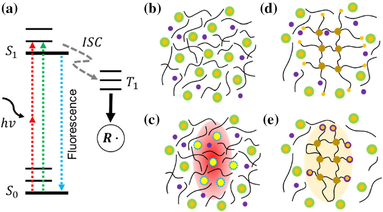
    Fig. 2. (a) Energy-level diagram for photoinitiator molecules for one-photon and two-photon excitation. hν, photon energy; S0, ground state; S1, excited singlet state; T1, triplet state; ISC, intersystem crossing. (b)–(e) Schematic of the reaction mechanism for liquid photoresin containing monomers/oligomers (black lines), photoinitiators (green annulus) with radicals (yellow circles), and photoinhibitors (purple dots) (b) before and (c) after initiation, where the red area is illuminated by the irradiation source, and the blue corona is the emission fluorescence. Schematic of the sequential reaction mechanism for (d) chain reaction propagation and (e) termination/quenching procedure. The shaded yellow area represents the photopolymerized volume.
    Main scanning methods for point-scanning 3D printing based on (a) XYZ translational stage and (b) optical deflection via beam delivery components. Main methods to generate multiple foci for 3D printing based on (c) microlens array; (d) diffractive optical elements (DOEs); and (e) spatial light modulator (SLM).
    Fig. 3. Main scanning methods for point-scanning 3D printing based on (a) XYZ translational stage and (b) optical deflection via beam delivery components. Main methods to generate multiple foci for 3D printing based on (c) microlens array; (d) diffractive optical elements (DOEs); and (e) spatial light modulator (SLM).
    Rapid multi-focus two-photon printing technique: (a) schematic for the 3D printing system and (b)–(d) scanning electron micrographs of the 3D printed mechanical metamaterial (reprinted from Wiley-VCH: Advanced Functional Materials [90], copyright 2020).
    Fig. 4. Rapid multi-focus two-photon printing technique: (a) schematic for the 3D printing system and (b)–(d) scanning electron micrographs of the 3D printed mechanical metamaterial (reprinted from Wiley-VCH: Advanced Functional Materials [90], copyright 2020).
    Holographic multi-focus 3D printing technique: (a) system schematic; (b) serial hologram in the printing process; (c) 4−f system for adjusting the size of the printed parts; and (d) 3D objects printed by the system (reprinted by permission from OSA: Optics Letters [95], copyright 2019).
    Fig. 5. Holographic multi-focus 3D printing technique: (a) system schematic; (b) serial hologram in the printing process; (c) 4f system for adjusting the size of the printed parts; and (d) 3D objects printed by the system (reprinted by permission from OSA: Optics Letters [95], copyright 2019).
    DMD-based multi-focus 3D printing technique: (a) schematic for DMD 3D printing system; (b) model and SEM images of printed results of octet truss realized by single-focus two-photon polymerization; and (c) comparison of fabrication results of woodpile structures with single focus, two foci, and three foci (reprinted from Springer Nature: Nature Communications [104], copyright 2019).
    Fig. 6. DMD-based multi-focus 3D printing technique: (a) schematic for DMD 3D printing system; (b) model and SEM images of printed results of octet truss realized by single-focus two-photon polymerization; and (c) comparison of fabrication results of woodpile structures with single focus, two foci, and three foci (reprinted from Springer Nature: Nature Communications [104], copyright 2019).
    (a) Schematics of the multi-material projection micro-stereolithography system and its overall process; (b) Taiji symbol patterned cylinder made of two different materials; (c) multi-material bilayer micro-capillary structure with fluorescent substances; and (d) 3D helix composed of three different parts: particle-free center pillar, two helix arms loaded with copper, and alumina nano-particles (reprinted by permission from Elsevier B.V.: Additive Manufacturing [115], copyright 2019).
    Fig. 7. (a) Schematics of the multi-material projection micro-stereolithography system and its overall process; (b) Taiji symbol patterned cylinder made of two different materials; (c) multi-material bilayer micro-capillary structure with fluorescent substances; and (d) 3D helix composed of three different parts: particle-free center pillar, two helix arms loaded with copper, and alumina nano-particles (reprinted by permission from Elsevier B.V.: Additive Manufacturing [115], copyright 2019).
    (a) Schematic for the high-area rapid printing based on mobile–liquid interface; (b) velocity profiles under the printed part at different flow speeds; (c) inset of the slip boundary flow profile under the part; and (d) a ∼1.2- m hard polyurethane acrylate lattice (reprinted by permission from AAAS: Science [116], copyright 2019).
    Fig. 8. (a) Schematic for the high-area rapid printing based on mobile–liquid interface; (b) velocity profiles under the printed part at different flow speeds; (c) inset of the slip boundary flow profile under the part; and (d) a 1.2-m hard polyurethane acrylate lattice (reprinted by permission from AAAS: Science [116], copyright 2019).
    (a) 3D printing using a layer-by-layer projection of digital masks; (b) optical configuration of the FP-TPL system; (c) zoomed-in schematic of temporal focusing in the focal volume of the objective lens; and (d) structures printed by the FP-TPL system (reprinted by permission from AAAS: Science [123], copyright 2019).
    Fig. 9. (a) 3D printing using a layer-by-layer projection of digital masks; (b) optical configuration of the FP-TPL system; (c) zoomed-in schematic of temporal focusing in the focal volume of the objective lens; and (d) structures printed by the FP-TPL system (reprinted by permission from AAAS: Science [123], copyright 2019).
    (a) Optical configuration of the holographic volumetric 3D fabrication system; (b)–(g) structures fabricated with a single exposure (reprinted from AAAS: Science Advances [125], copyright 2017).
    Fig. 10. (a) Optical configuration of the holographic volumetric 3D fabrication system; (b)–(g) structures fabricated with a single exposure (reprinted from AAAS: Science Advances [125], copyright 2017).
    (a) Printing mechanism of the computed axial lithography; (b) configuration of the computed axial lithography; and (c) various 3D structures printed with different materials (reprinted by permission from AAAS: Science [126], copyright 2019).
    Fig. 11. (a) Printing mechanism of the computed axial lithography; (b) configuration of the computed axial lithography; and (c) various 3D structures printed with different materials (reprinted by permission from AAAS: Science [126], copyright 2019).
    (a) Configuration of tomographic 3D fabrication system with feedback; (b) étendue-limited optical resolution; and (c) comparison between the tomographic 3D printed artery with and without feedback (reprinted from Springer Nature: Nature Communications [128], copyright 2020).
    Fig. 12. (a) Configuration of tomographic 3D fabrication system with feedback; (b) étendue-limited optical resolution; and (c) comparison between the tomographic 3D printed artery with and without feedback (reprinted from Springer Nature: Nature Communications [128], copyright 2020).
    Summary of different 3D printing techniques plotted versus the resolution (lower logarithmic horizontal scale) and throughput, evaluated with volumetric processing rate (left logarithmic vertical scale): volumetric fabrication (black squares); layer-scanning-based manufacturing (red spheres); single-focus point-scanning fabrication (blue hexagons); multi-focus point-scanning fabrication (green stars); and multi-focus random-access fabrication (enlarged green stars). The labels of the data point refer to the serial numbers of corresponding references. For multi-focus fabrication, the number of foci used is reported next to the reference number after the hyphen.
    Fig. 13. Summary of different 3D printing techniques plotted versus the resolution (lower logarithmic horizontal scale) and throughput, evaluated with volumetric processing rate (left logarithmic vertical scale): volumetric fabrication (black squares); layer-scanning-based manufacturing (red spheres); single-focus point-scanning fabrication (blue hexagons); multi-focus point-scanning fabrication (green stars); and multi-focus random-access fabrication (enlarged green stars). The labels of the data point refer to the serial numbers of corresponding references. For multi-focus fabrication, the number of foci used is reported next to the reference number after the hyphen.
    Illustration of different methods for printing objects with super-resolution feature sizes: (a) precise power control; (b) two-photon polymerization; and (c) STED-lithography: intensity profiles of the polymerization light (black) and depletion light (blue), and exposure-dose profile (red). Definition of resolution by (d) Sparrow limit and (e) Rayleigh limit.
    Fig. 14. Illustration of different methods for printing objects with super-resolution feature sizes: (a) precise power control; (b) two-photon polymerization; and (c) STED-lithography: intensity profiles of the polymerization light (black) and depletion light (blue), and exposure-dose profile (red). Definition of resolution by (d) Sparrow limit and (e) Rayleigh limit.
    Mesoscale sub-micrometer 3D printing: (a) mesoscale structures printed via different scanning methods and (b) structures printed by the synchronization of the galvo-scanner and linear stage (reprinted by permission from OSA: Optics Express [145], copyright 2019). (c) Optimized printing strategy against the shrinkage and proximity effect and (d) printed structures after optimization (reprinted from Springer Nature: Scientific Reports [146], copyright 2019).
    Fig. 15. Mesoscale sub-micrometer 3D printing: (a) mesoscale structures printed via different scanning methods and (b) structures printed by the synchronization of the galvo-scanner and linear stage (reprinted by permission from OSA: Optics Express [145], copyright 2019). (c) Optimized printing strategy against the shrinkage and proximity effect and (d) printed structures after optimization (reprinted from Springer Nature: Scientific Reports [146], copyright 2019).
    ApproachFeedstock MaterialProcessPrinting Rate (mm3/h)Resolution (μm)Potential ApplicationsReferences
    FFDPolymer filamentHeat treatment2×1035×103200–400Prototyping, advanced composite[28,29]
    DIWLiquid with dispersion of particlesCoagulation, thermal curing, gluing2×1034×1030.268–610Biomedicine[32,33,51,52]
    DEDMetal, alloyFocused ion/electron beam/arc/laser7.2×10103.6×1050.008–40Aerospace, retrofitting, biomedicine[36,37]
    LOMPolymer, ceramics, metal, alloy, paperLaminating30Electronics, smart structures[39]
    EHDPMetal, alloyApplication of voltage7.2×1063.60×1040.07–3Retrofitting, biomedicine, electronics[36,40,41]
    PBFFine powder of polymer, ceramics, metal, alloyIllumination of focused laser spot4.5×10680–250Biomedicine, lightweight structures[34]
    P3DPResin (polymer, hybrid polymer-ceramic, functionalized polymer)Illumination of focused laser spot or optical patterns6.9×1075.0×1060.052–200Prototyping, biomedicine[4448,53,54]
    LCVDGaseous reactantsIllumination of focused laser spot3.15×10140High purity/quality crystals[50]
    Table 1. Summary of Micro-3D Printing Methods in Terms of Material, Process, Fabrication Rate, and Resolution
    Wei Lin, Dihan Chen, Shih-Chi Chen. Emerging micro-additive manufacturing technologies enabled by novel optical methods[J]. Photonics Research, 2020, 8(12): 1827
    Download Citation