
Ji-Yan Lin, Shu-Yu Lin. Two-dimensional ultrasonic plastic welding system based on phononic crystal dislocation theory [J]. Acta Physica Sinica, 2020, 69(18): 184302-1
- Acta Physica Sinica
- Vol. 69, Issue 18, 184302-1 (2020)
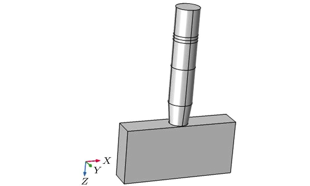
Fig. 1. Structural diagram of two-dimensional ultrasonic plastic welding vibration system.
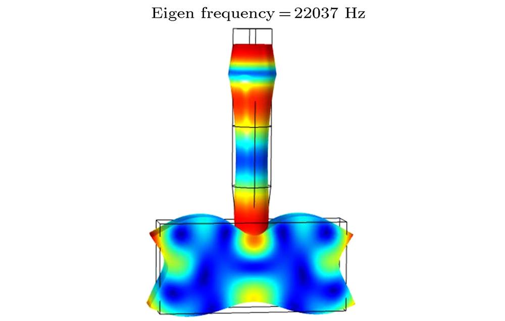
Fig. 2. Modal diagram of two-dimensional ultrasonic plastic welding vibration system.
Fig. 3. X -direction longitudinal relative displacement distribution of radiating surface of tool head.
Fig. 4. Two-dimensional tool head based on near-period phononic crystal multiple-grooves: (a) Structure; (b) dimensions; (c) cell model diagram.
Fig. 5. Acceleration response curve of the cell structure in the X direction.
Fig. 6. Supercell model of a two-dimensional tool head based on near-period phononic crystal homogenous dislocation junction.
Fig. 7. Schematic diagram of near-period phononic crystal supercell based on homogenous dislocation junction.
Fig. 8. X -direction acceleration response curve of supercell structure based on near-period phononic crystal homogenous dislocation junction.
Fig. 9. Comparison of acceleration response curves of the two structures in the X direction.
Fig. 10. Structure diagram and modal diagram of two-dimensional ultrasonic plastic welding vibration system based on near-period phononic crystal homogenous dislocation junction.
Fig. 11. Displacement distribution diagram of tool head radiating surface of system based on near-period phononic crystal homogenous dislocation junction and its comparison with radiation surface displacement distribution with non-grooved system and system.
Fig. 12. Dimensional diagram of tool head based on near-period phononic crystal inclined groove structure.
Fig. 13. Structural diagram and modal diagram of two-dimensional ultrasonic plastic welding vibration system based on a near-period phononic crystal inclined groove structure.
Fig. 14. Displacement distribution diagram of tool head radiating surface of system based on near-period phononic crystal inclined groove structure and its comparison with the displacement distribution of radiating surface of tool head with homogenous dislocation in near-period phononic crystal
Fig. 15. Influence of the height of the inclined grooves on the resonance frequency of the system.
Fig. 16. Influence of the height of the inclined grooves on the range of amplitude variation
Fig. 17. Influence of the width of the inclined grooves on the resonance frequency of the system.
Fig. 18. Influence of the width of the inclined grooves on the range of amplitude variation.
Fig. 19. Influence of the angle of the inclined grooves on the resonance frequency of the system
Fig. 20. Influence of the angle of the inclined grooves on the range of amplitude variation
Fig. 21. Relationship between dr and the angle difference of outer and inner inclined grooves.

Set citation alerts for the article
Please enter your email address
© Copyright 2018-2021 | Chinese Laser Press. All Rights Reserved 沪ICP备15018463号-20