
Rongqiao Wan, Guoqiang Li, Xiang Gao, Zhiqiang Liu, Junhui Li, Xiaoyan Yi, Nan Chi, Liancheng Wang. Nanohole array structured GaN-based white LEDs with improved modulation bandwidth via plasmon resonance and non-radiative energy transfer[J]. Photonics Research, 2021, 9(7): 1213
- Photonics Research
- Vol. 9, Issue 7, 1213 (2021)
Abstract
1. INTRODUCTION
It is significant to embed visible light communication (VLC) into GaN-based white LEDs (WLEDs) to integrate lighting and communications. The lighting-oriented WLEDs are usually obtained by exciting phosphors with GaN-based blue LEDs, whose modulation bandwidth is severely limited (only few MHz) [1] by the following factors: the relatively long lifetime of phosphor and slow Stokes transfer process [2]; resistance-capacitance (RC) time delay of the broad area WLEDs; and the quantum-confined Stark effect (QCSE) of the InGaN/GaN quantum wells (QWs) from an intrinsic piezoelectric polarization field [3,4].
Some approaches have been reported to increase the modulation bandwidth, such as optimizing the structure of the active area to improve the carrier radiative recombination rate, reducing the size of the LED chip to reduce the RC constant [5], and designing micro/nano structures to reduce the QCSE [3]. In addition, the Purcell effect of microcavity structures [6] or surface plasmons (SPs) can also be used to enhance the spontaneous emission rate [7]. Meanwhile, novel color conversion materials are proposed, including conjure polymer, quantum dots (QDs), and carbon dots [8–11]. The non-radiative resonant energy transfer (NRET) between QWs and QDs has been demonstrated to accelerate the recombination of carriers, using exciton–exciton coupling [12–14], which is beneficial to improve the modulation bandwidth.
In this work, we fabricated the QW-QD-SP coupled WLEDs based on a nanohole LED (H-LED) structure. When QDs and Ag nanoparticles (NPs) are mixed into the nanoholes (M-LED), modulation bandwidth is enhanced by 1.76 times compared to H-LEDs filled with QDs alone (QD-LED) at 60 mA. Both the carrier recombination rate and the optical power of the WLEDs are enhanced, and the chromaticity parameters of white light are improved, benefiting from the effective QW-QD-SP coupling. The higher optical power and modulation bandwidth lead to a higher data rate and higher signal-to-noise ratio (SNR) under the forward error correction (FEC). At a low current density of (60 mA), the M-LED exhibits a data rate of 2.21 Gb/s, which is 77% higher than that of a QD-LED.
Sign up for Photonics Research TOC. Get the latest issue of Photonics Research delivered right to you!Sign up now
2. EXPERIMENTS
The fabrication process of H-LEDs is depicted in Fig. 1. GaN-based blue epitaxial wafers on sapphire substrate were adopted, and a 100 nm thick indium tin oxide (ITO) layer was deposited by electron beam evaporation, followed by a 300 nm thick layer by plasma-enhanced chemical vapor desposition (PECVD). Then, a 120 nm thick nanohole structure mask was obtained on the layer using nano-imprint lithography, and then the nanohole pattern is transferred to the layer using reactive ion etching. Next, the p-GaN, multiple quantum well (MQW), n-GaN, and mesa were etched by inductive coupled plasma, followed by a 5 nm thick layer deposited by PECVD to protect the side wall of the nanohole. Finally, when the residual silicon oxide is removed by wet etching, the n- and p-type contact Cr/Al/Ti/Au was evaporated. The chip size is .
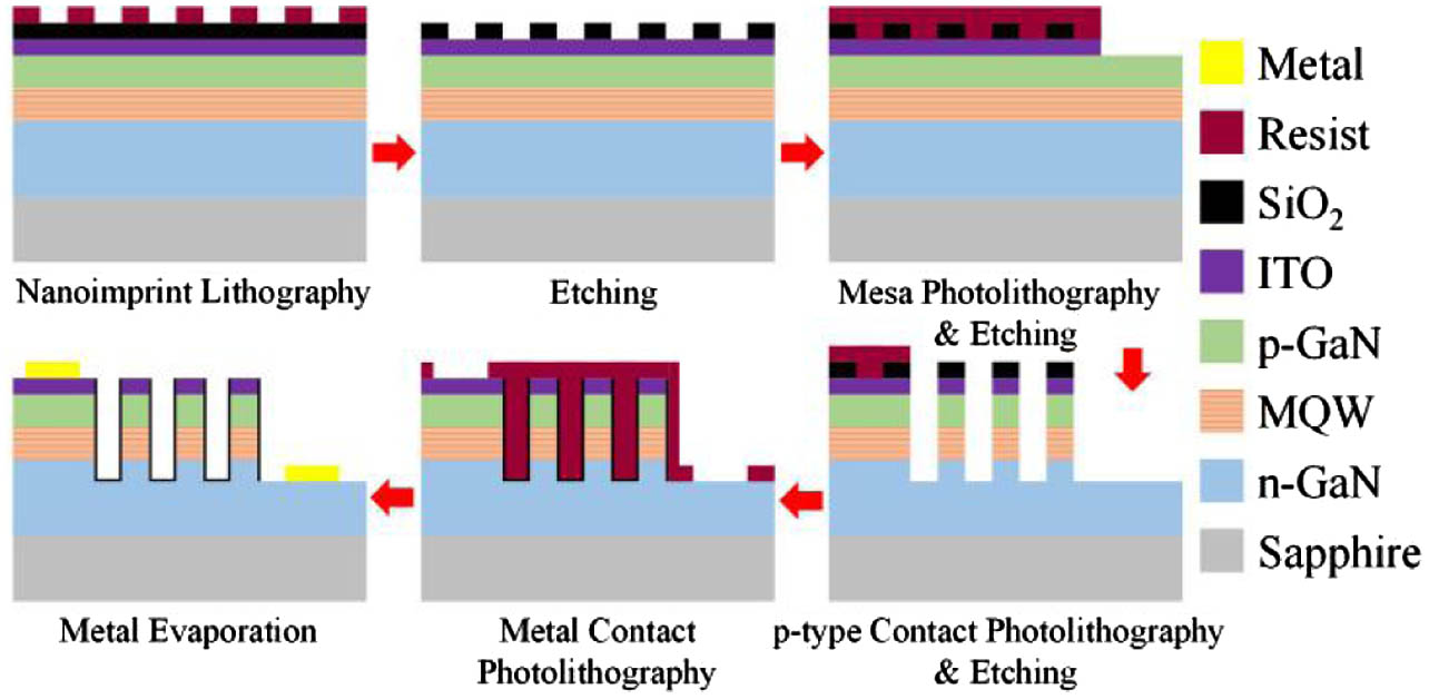
Figure 1.Fabrication process of H-LEDs.
3. RESULTS AND DISCUSSION
Figure 2(a) shows the top view scanning electron microscope (SEM) image of the bare H-LED, where the nanoholes are arranged in a hexagonal pattern with a period of 1 μm and a diameter of 550 nm [Fig. 2(b)]. Figures 2(c) and 2(d) show the cross-sectional SEM image of the H-LED with and without Ag NPs and QDs, with approximately 1.5 μm in depth. It can be observed that the holes exhibit an inverted trapezoid shape, with QDs and Ag NPs successfully infiltrated into the nanoholes.
![]()
Figure 2.(a) Top view SEM image of bare H-LED; (b) high magnification SEM image for the area marked by the red box in (a); (c) and (d) cross-sectional view of SEM image of bare nanoholes and nanoholes filled with QDs and Ag NPs, respectively.
Figure 3(a) depicts electroluminescence (EL) spectrum of the H-LED and absorption spectra of Ag NPs. The emission peak of H-LED was located at 456.5 nm, and absorption peaks of Ag NPs were located at 450 nm, which overlap with the emission of H-LED.
![]()
Figure 3.(a) EL spectra of H-LED and absorption spectra of Ag NPs. (b) Decay curves of QWs of H-LED, QD-LED, and M-LED, respectively. (c) Possible energy transfer processes in the hybrid structure.
The photoluminescence (PL) decay curves of QWs of the H-LED, QD-LED, and M-LED are displayed in Fig. 3(b). The decay rate is gradually increased after mixing with QDs and QD-Ag NPs due to the NRET and localized surface plasmon resonance (LSPR) effect.
The decay curves are fitted with a double-exponential function, Carriers’ Lifetime of QWs of H-LED, QD-LED, and M-LEDSample H-LED 1.25 80.5 QD-LED 1.07 79.6 M-LED 0.85 73.0
Figure 3(c) depicts the mechanism and possible energy transfer paths in such a hybrid structure. For QD-LEDs, since NRET strongly depends on the distance between the donor and the acceptor, exciton close to the side wall of the nanohole () can undergo NRET. This process can not only effectively improve the color conversion efficiency, but also significantly enhance the decay rate of exciton in the QWs [12–14]. It can also be seen from Table 1 that, compared to H-LEDs, NRET accelerates the recombination rate of carriers so that () decreases from 1.25 ns (80.5 ns) to 1.07 ns (79.6 ns). Because the absorption peak of Ag NPs matches the emission wavelength of the H-LED, when the exciton is located within the fringing field of LSPs generated on Ag NPs, the recombination rate of the exciton will also increase. When the distance is less than 4 nm, a quenching effect will also occur. For M-LEDs, the coupling effect of QWs with LSPR and NRET makes the recombination rate of exciton in QWs faster, resulting in further decreasing from 1.07 ns to 0.85 ns. Simultaneously, the NRET process between Ag NPs and QDs can further reduce the loss of Stokes conversion.
The I-V characteristics of the H-LED with and without Ag NPs are presented in Fig. 4(a). It can be observed that both curves exhibit typical rectifying characteristics, and the two curves coincide with each other well after turn-on. The frequency response of QD-LEDs and M-LEDs operated at current 60 mA is shown in Fig. 4(b). We can clearly see that the bandwidth of the M-LED is significantly higher than that of the QD-LED. The modulation bandwidth of M-LED, at 260 MHz, is 1.76 times higher than that of the QD-LED, at 148 MHz, indicating that excitons in the QWs effectively couple with the SPs, leading to a faster recombination rate.
![]()
Figure 4.(a)
To explore the effect of SPs on nanohole-based WLEDs, the EL spectra of the QD-LED and M-LED are measured at 20 mA, as shown in Fig. 5(a). Compared to QD-LEDs, M-LEDs have higher emission intensity. Different from the holes filled with Ag NPs alone, the mixture of Ag NPs and QDs can not only improve the scattering effect of SPs, but also improve the emission rate of QDs. Figures 5(b)–5(d) show the optical power, color rendering index (CRI), and the CIE-1931 chromaticity coordinates of QD-LEDs and M-LEDs versus current. As shown in Fig. 5(b), the optical power of the QD-LED initially increased, approaching saturation at 30 mA, and remained basically unchanged with an increased current. This is because the QDs located farther from the side wall of nanohole have lower absorption and color conversion rates than the QDs near the side wall of nanohole, which limits the increase in optical power. However, after the Ag NPs are incorporated, the optical power increases and does not reach the saturation point before 60 mA (2.4 mW), which is 43% higher than that without Ag NPs at 60 mA. This is due to the Purcell effect of the SPs, which increases the QW’s emission intensity, while its higher scattering efficiency increases the absorption rate of the QDs, and the NRET path between Ag NPs and QDs also makes the color conversion efficiency of the QDs higher. For QD-LEDs, the CRI exhibits a maximum of 86.4 at 30 mA and then decreases. This is due to the rapid growth of blue light resulting in spectral inhomogeneity. The chromaticity coordinates are monotonically blue shifted [from (0.2631, 0.2651) to (0.2419, 0.2386), and there is a correlated color temperature ] with the increasing current. After the Ag NPs are incorporated, the CRI is overall improved at all current injection levels and exhibits a monotonically increasing trend versus current with a maximum of 91.2 at 60 mA, compared to without Ag NPs. Simultaneously, the chromaticity coordinates of M-LEDs [from (0.261, 0.2824) to (0.2468, 0.2626)] are shifted to yellow relative to QD-LEDs, and the CCT is decreased overall. Similarly, the SPs effect of Ag NPs, results in an increased color conversion efficiency from blue to QDs. The increased long wavelength ratio is beneficial to obtain warmer white light with a lower CCT, and a more balanced white light spectrum is also favorable for a higher CRI.
![]()
Figure 5.(a) EL spectra of the QD-LED and M-LED under 20 mA; (b) optical power; (c) CRI; and (d) CIE-1931 chromaticity coordinates of QD-LED and M-LED versus current.
Distribution of the spectrum also will affect the bandwidth of WLEDs. Since the fluorescence lifetime of color conversion materials is usually longer compared to the carrier lifetime of LED chips, the larger the proportion of chip emission peaks in the spectrum, the higher the corresponding bandwidth. Through multipeak fitting of the spectrum in Fig. 5(a), the blue light proportion of QD-LEDs and M-LEDs is 44.6% and 44%, respectively. The bandwidth of M-LEDs is higher than that of QD-LEDs. This indicates that the Purcell effect of SPs can effectively raise the spontaneous emission rate, and decrease the carrier recombination lifetime. It not only improves the bandwidth of white light, but also optimizes the chromaticity parameters of white light.
Furthermore, to justify the applicability to VLC, the data rate and bit error rate (BER) of the binary phase shift keying (BPSK) signal at different currents were measured in free space using nonlinearity mitigation and equalization technology. As shown in Fig. 6(a), because the larger injection current can achieve a shorter differential carrier lifetime, this leads to a higher modulation bandwidth of the LED. So, as the injection current increases, the achievable data rate gradually increases, and tends to saturate at 50 mA. The maximum data rates of QD-LED and M-LED are 825 Mb/s and 1.03 Gb/s, respectively, at 60 mA. The achievable data rate of M-LED at each current is higher than that of QD-LED, below the FEC threshold of . This also proves that under the effect of SPs, the M-LED has a higher modulation bandwidth than the QD-LED, so it can achieve a higher data rate.
![]()
Figure 6.(a) Data rate and BER of BPSK signal at different currents. (b) BER versus data rate of BPSK signal at 60 mA; insets: constellation diagrams at points (a), (b), (c), and (d).
In addition, the BER versus the data rate of the QD-LED and the M-LED at 60 mA was tested based on a pulse amplitude modulation (PAM) scheme. As shown in Fig. 6(b), the maximum achievable data rates of QD-LED and M-LED are 825 Mb/s with a BER of and 1.03 Gb/s with a BER of , respectively, which are below the FEC threshold of . The insets present the constellation diagrams of BPSK signal of QD-LED and M-LED at points (a), (b), (c), (d), respectively. It can be seen that under the FEC threshold, M-LEDs can achieve a higher data rate under the similar SNR, also due to the effect of SPs, which makes M-LEDs have a higher modulation bandwidth and optical power compared to the QD-LEDs.
To further compare the performance of the QD-LEDs and M-LEDs, we tested the capacity of the VLC system by employing a bit loading discrete multitone (DMT) modulation format. The data rate versus the signal bandwidth of the QD-LED and the M-LED at 60 mA is illustrated in Fig. 7(a). It can be seen that increasing the signal bandwidth increases the data rate. The highest available data rate of 2.21 Gb/s for M-LEDs and 1.25 Gb/s for QD-LEDs can be achieved at a bandwidth of 500 MHz and 475 MHz under the FEC threshold of . However, when the signal bandwidth is too large, the VLC system is in SNR limitation; therefore, the data rate decreases under the same power budget. Under the highest data rate, quadrature amplitude modulation (QAM) order and SNR versus DMT subcarrier index of the QD-LED and the M-LED are shown in Figs. 7(b) and 7(c). It is observed that the received SNR of M-LED is greater than that of QD-LED, which makes the M-LED achieve a higher data rate. In addition, the frequency response of the M-LED is better than that of the QD-LED, especially at high frequency. The corresponding constellation diagrams are shown in Fig. 7(d).
![]()
Figure 7.(a) Data rate versus bandwidth; QAM order and SNR versus DMT subcarrier index of the (b) QD-LED and (c) M-LED. (d) Constellation diagrams.
Table 2 lists and compares the data rate of GaN-based single chip WLEDs reported in recent years. It is not difficult to see that to obtain a higher data rate, it usually must be operated at a high current density of level, which then helps it attain a lower differential carrier lifetime and thus larger modulation bandwidth. However, this should undoubtedly lead to a large drop in efficiency and heat dissipation problems. Therefore, it is significant to achieve a high data rate at a low current density. Our proposed M-LED exhibits a data rate of 2.21 Gb/s at a low current density of (60 mA), which is 77% higher than that of the QD-LED, potentially capable to be the candidate to realize a high data rate VLC at low current density. Achievements Applying GaN-Based Single-Chip WLEDsLED Type Current Density Modulation Scheme Data Rate Refs. μLED + polymer color converter Orthogonal frequency division multiplexing (OFDM) 1.68 Gb/s [ Phosphorescent white LED — OFDM (bit and power loading) 2.0 Gb/s [ μLED + QDs Non-return-to-zero on–off keying (NRZ-OOK) 300 Mb/s [ Micro-LED + QDs NRZ-OOK 675 Mb/s [ No phosphor NRZ-OOK 127 Mb/s [ Nanohole-LED + QDs + Ag NPs DMT 2.21 Gb/s This work
By tailoring the coupling between QWs and Ag SPs, the modulation performance of WLEDs can be further enhanced, since SPs also have a quench effect on radiative recombination if the distance between Ag SPs and QWs is too close. In addition, the CCT of the M-LED is still too high, which belongs to cool white light. This is due to the still-limited QD infiltration in the nanoholes and the QD self-absorption. Further structure optimization will be carried out for M-LEDs to increase its modulation bandwidth and lighting performance.
4. SUMMARY
To conclude, we demonstrated what we believe, to the best of our knowledge, are novel plasmonic WLEDs based on the nanohole array structure. By infiltrating with CdSe/ZnS core/shell QDs and Ag NPs, M-LEDs exhibit a shorter carrier lifetime compared to the QD-LEDs and H-LEDs by TRPL measurements, which is mainly owing to the NRET process and SPs coupling. In addition, the current dependent chromaticity parameters and frequency responses of the M-LEDs also were measured. Compared to the QD-LEDs, the chromaticity parameters of M-LEDs are optimized, with a maximum CRI of 91.2, the optical power increases by 43% at 60 mA, and the CCT is lower. In addition, the −20 dB modulation bandwidth of an M-LED is 1.76 times larger than that of a QD-LED, which results in a higher data rate of 2.21 Gb/s (77% increment) and higher SNR at a low current density of (60 mA). Therefore, we believe our findings could provide a promising approach for WLEDs in lighting and VLC applications.
References
[1] S. Rajbhandari, J. J. D. McKendry, J. Herrnsdorf, H. Chun, G. Faulkner, H. Haas, I. M. Watson, D. O’Brien, M. D. Dawson. A review of gallium nitride LEDs for multi-gigabit-per-second visible light data communications. Semicond. Sci. Technol., 32, 023001(2017).
[2] D. Xue, C. Ruan, Y. Zhang, H. Chen, X. Chen, C. Wu, C. Zheng, H. Chen, W. W. Yu. Enhanced bandwidth of white light communication using nanomaterial phosphors. Nanotechnology, 29, 455708(2018).
[3] T. C. Lin, Y. T. Chen, Y. F. Yin, Z. X. You, H. Y. Kao, C. Y. Huang, Y. H. Lin, C. T. Tsai, G. R. Lin, J. J. Huang. Large-signal modulation performance of light-emitting diodes with photonic crystals for visible light communication. IEEE Tran. Electron Devices, 65, 4375-4380(2018).
[4] R. Wan, X. Gao, L. Wang, S. Zhang, X. Chen, Z. Liu, X. Yi, J. Wang, J. Li, W. Zhu, J. Li. Phosphor-free single chip GaN-based white light emitting diodes with a moderate color rendering index and significantly enhanced communications bandwidth. Photon. Res., 8, 1110-1117(2020).
[5] H. Cao, S. Lin, Z. Ma, X. Li, J. Li, L. Zhao. Color converted white light-emitting diodes with 637.6 MHz modulation bandwidth. IEEE Electron. Device Lett., 40, 267-270(2018).
[6] R. G. Baets, D. G. Delbeke, R. Bockstaele, P. Bienstman. Resonant cavity light-emitting diodes: a review. Proc. SPIE, 4996, 74-86(2003).
[7] L. Ferrari, J. S. T. Smalley, H. Qian, A. Tanaka, D. Lu, S. Dayeh, Y. Fainman, Z. Liu. Design and analysis of blue InGaN/GaN plasmonic LED for high-speed, high-efficiency optical communications. ACS Photon., 5, 3557-3564(2018).
[8] H. Chun, P. Manousiadis, S. Rajbhandari, D. A. Vithanage, G. Faulkner, D. Tsonev, J. J. D. McKendry, S. Videv, E. Xie, E. Gu, M. D. Dawson, H. Haas, G. A. Turnbull, I. D. W. Samuel, D. O’Brien. Visible light communication using a blue GaN μLED and fluorescent polymer colour converter. IEEE Photon. Technol. Lett., 26, 2035-2038(2014).
[9] S. Mei, X. Liu, W. Zhang, R. Liu, L. Zheng, R. Guo, P. Tian. High-bandwidth white-light system combining a micro-LED with perovskite quantum dots for visible light communication. ACS Appl. Mater. Interfaces, 10, 5641-5648(2018).
[10] Z. Tian, P. Tian, X. Zhou, G. Zhou, S. Mei, W. Zhang, X. Zhang, D. Li, D. Zhou, R. Guo, S. Qu, A. L. Rogach. Ultraviolet-pumped white light emissive carbon dot based phosphors for light-emitting devices and visible light communication. Nanoscale, 11, 3489-3494(2019).
[11] R. Wan, S. Zhang, Z. Liu, X. Yi, L. Wang, J. Wang, J. Li, W. Zhu, J. Li. Simultaneously improve the luminous efficiency and color-rendering index of GaN-based white-light-emitting diodes using metal localized surface plasmon resonance. Opt. Lett., 44, 4155-4158(2019).
[12] Z. Zhuang, J. Dai, B. Liu, X. Guo, Y. Li, T. Tao, T. Zhi, G. Zhang, Z. Xie, H. Ge, Y. Shi, Y. Zheng, R. Zhang. Improvement of color conversion and efficiency droop in hybrid light-emitting diodes utilizing an efficient non-radiative resonant energy transfer. Appl. Phys. Lett., 109, 141105(2016).
[13] Z. Zhuang, X. Guo, B. Liu, F. Hu, Y. Li, T. Tao, J. Dai, T. Zhi, Z. Xie, P. Chen, D. Chen, H. Ge, X. Wang, M. Xiao, Y. Shi, Y. Zheng, R. Zhang. High color rendering index hybrid III-nitride/nanocrystals white light-emitting diodes. Adv. Funct. Mater., 26, 36-43(2016).
[14] C. Krishnan, M. Brossard, K. Y. Lee, J. K. Huang, C. H. Lin, H. C. Kuo, M. D. B. Charlton, P. G. Lagoudakis. Hybrid photonic crystal light-emitting diode renders 123% color conversion effective quantum yield. Optica, 3, 503-509(2016).
[15] X. Huang, S. Chen, Z. Wang, J. Shi, Y. Wang, J. Xiao, N. Chi. 2.0-Gb/s visible light link based on adaptive bit allocation OFDM of a single phosphorescent white LED. IEEE Photon. J., 7, 7904008(2015).

Set citation alerts for the article
Please enter your email address
© Copyright 2018-2021 | Chinese Laser Press. All Rights Reserved 沪ICP备15018463号-20