
Jaffar Kadum, Ranjan Das, Arijit Misra, Thomas Schneider. Brillouin-scattering-induced transparency enabled reconfigurable sensing of RF signals[J]. Photonics Research, 2021, 9(8): 1486
- Photonics Research
- Vol. 9, Issue 8, 1486 (2021)
Abstract
1. INTRODUCTION
The tremendous surge in data traffic required for high-speed communications and the Internet of things demands an efficient allocation and utilization of the available spectrum. The scarcity of the radio spectrum is one of the most challenging issues for future communication networks. A potential solution to diminish this issue is dynamic spectrum sensing, which is the process of detecting the voids (unused spectra) in the costly incoming spectrum [1,2]. Modern applications such as cognitive radio, radar, and lidar require a real-time frequency tracking to capture the dynamic alterations of the spectrum [3–5]. This real-time spectrum analysis is carried out predominantly by Fourier transformation in digital signal processors (DSPs). However, electronics-based conventional DSPs suffer from major drawbacks such as intensive computational hardware requirement, exorbitant power consumption, low speed, and limited bandwidth, which curb the capability of this approach to a few hundreds of megahertz only and hence prevent its application for wideband 5G and millimeter-wave (mm-wave) communication systems [4].
Dispersive “phasers” [6,7] were proposed as an analog signal processing unit to segregate the microwave frequencies. Recently, a metasurface-based spatial phaser [8] was demonstrated successfully for X-band frequency discrimination, which involves a complex circuit synthesis and design method. Nevertheless, losses and static configuration (non-reconfigurable) impose substantial challenges to fit them for 5G or mm-wave systems. Also, sampling at such high-frequency bands is quite challenging in the electrical domain. By contrast, photonic devices are more conducive due to their immanent high bandwidth, low loss, and high immunity to electromagnetic interference.
Modern radio frequency (RF) signal processing applications have rigorous requirements in terms of bandwidth, processing speed, and power consumption. Microwave photonics, which is the field of processing, measurement, and manipulation of the RF signals after being upconverted to the optical domain, has attracted abundant interest in recent years as a promising solution to these challenges due to the ultra-high optical bandwidth and the availability of low-loss optical fibers [4,9,10]. Many microwave photonic schemes of the past were bulky, expensive, and sensitive to external perturbations. However, photonic integration can significantly enhance the performance of microwave photonics due to its several advantages such as small footprint, high performance, and low cost [10].
Sign up for Photonics Research TOC. Get the latest issue of Photonics Research delivered right to you!Sign up now
In photonics, usually a linear chromatic dispersion is used for a frequency-to-time mapping of the spectrum [11]. However, the time stretching by chromatic dispersion limits this approach to low-speed or even a static application [12]. Therefore, a short-time Fourier transform (FT) was implemented by calculating the FT of consecutive truncated sections of the incoming spectrum with a sweeping temporal time window [13]. However, to avoid the loss of information between time truncated windows and to track dynamic variations of the spectrum, a large number of FT calculations are required. Gap-free continuous spectrum measurement methods based on short-pulse temporal sampling and dispersive delay have been proposed in Refs. [14,15]. However, the demonstrated frequencies are limited to only a few gigahertz (0.5–2 GHz). A frequency measurement approach based on a waveguide Bragg grating on silicon has been presented in Ref. [5]. However, the measurements were limited to a coarse resolution of 1 GHz. Although several electrical microwave devices and optics-based solutions have been realized for spectrum sensing, a simple reconfigurable, wideband, and ultra-fast temporal spectrum sniffing, which may outperform existing DSP and enhances the aptness of real-time analog signal processing at 5 G and mm-wave frequency bands, is still missing.
In this paper, we present for the first time, to the best of our knowledge, a novel spectrum sensing technique, which exploits Brillouin-scattering-induced transparency (BIT). Based on a simple setup and basic optical components, the proposed method is fully reconfigurable and feasible for different frequency bands. A predefined group delay difference between the input frequencies is obtained by an optical fiber as a slow light medium. However, the method can be fully integrated into a chip.
2. THEORY
A. SBS-Based Slow Light
Stimulated Brillouin scattering (SBS) is the non-linear effect with the smallest threshold and interaction bandwidth. The SBS can be seen as a non-linear interaction between a pump and a counter-propagating Stokes wave mediated by an acoustic wave (density modulation of the medium). Thus, a part of the pump wave power is backscattered at this acoustic wave. The backscattered Stokes wave is shifted in frequency by the so-called Brillouin frequency shift , which is around 11 GHz in standard single-mode fibers (SSMFs) for a pump wavelength of 1550 nm [16]. Practically, if a relatively high intensity pump wave at frequency propagates in the fiber, it generates a gain for a counter-propagating wave with a frequency around and a loss for a wave with a frequency around . For a continuous pump wave, the complex Brillouin gain/loss spectrum is [17]
The lifetime of the acoustic phonons () constrains the Brillouin linewidth to 10–30 MHz [16] for a continuous unmodulated pump wave in SSMF and it can be further reduced with several methods [18–21]. The real part of Eq. (1) determines the gain/loss amplitude response of the probe wave. Due to the Kramers–Kronig relations, the amplitude change is accompanied by a phase change, and hence the imaginary part of Eq. (1) represents the frequency-dependent phase change (propagation constant) induced into the probe wave [22]. Due to the very narrow SBS interaction bandwidth, this abrupt change of the propagation constant will result in a sharp transition in the group index that leads to a group delay or advancement of the frequency components falling inside the Brillouin spectrum [23]. This group delay can be expressed as [24]
B. Brillouin-Scattering-Induced Transparency
The proposed spectrum sensing mechanism is based on the fact that a pulsed probe wave traveling in an SBS medium will experience a time delay given by Eq. (2) only if its frequency fits into the Brillouin gain spectrum. Therefore, depending on the center frequency of the Brillouin spectrum, different frequency components of the spectrum under test (SUT) can travel at different speeds and each frequency component can be mapped to a different time delay.
Two main effects are related with the SBS-induced delay, however, a broadening and amplification of the probe pulse [25–27]. The broadening, which is a result of the dispersion of the delay mechanism, does not affect the principle of the proposed method, since the delayed and non-delayed pulses are still distinguishable in the time domain and, if necessary, this broadening can be compensated by several methods [26–30]. On the contrary, the amplification process has the major impact. The SBS slow-light system can be seen as a Brillouin amplifier. For each nanosecond delay a gain of 1 dB is required [24]. Thus, the part of the pulse spectrum which experiences a 20 ns delay is amplified by 20 dB at the same time. This excess amplification makes the discrimination between delayed and non-delayed pulses not attainable in the time domain since the reference pulse is completely hidden by the amplified delayed pulse. However, since for a given setup all Brillouin parameters are known, it is possible to realize a spectrum discrimination between two pulses by a post-processing of the amplitude. However, such a post-processing is time consuming, averting the proposed technique for real-time applications. Thus, here the amplification associated with the delay has been compensated optically by reducing the net amplitude of the Brillouin gain spectrum through BIT [31,32]. Since the group index change depends on the shape of the Brillouin frequency spectrum, the imposed group delay will be preserved [32]. Such a BIT can be achieved by superposing a narrowband gain with a broader loss. Figure 1(a) shows the schematic diagram of the proposed technique. First, the incoming multi-frequency signal has to be transferred to an optical Gaussian pulse by an optical modulator. The spectrum of the pulsed multi-frequency signal can be seen in the dashed purple box in Fig. 1(a). Around the optical carrier, the two RF frequencies (1.8 and 5 GHz) with a Gaussian shape are present as two upper and lower sidebands [red curves in the purple box of Fig. 1(a)]. The SBS will be applied to the 5 GHz component, for instance [blue SBS gain in Fig. 1(a)]. If the SBS gain is frequency downshifted by , the frequency spacing between the optical carrier, carrying the two RF frequencies, and the blue Pump 1 is , with as the selected RF frequency (here 5 GHz). To compensate the gain, a broader loss has to be superimposed [31,32]. This is achieved by the green Pump 2 in Fig. 1(a). Thus, the frequency difference between the optical carrier and Pump 2 is . Therefore, the BIT profile can be scanned over different frequencies by only changing the pump wavelengths making the proposed method viable for different frequency bands. The imposed time delay can be adjusted either by changing the pump power or the length of the Brillouin medium [Eq. (2)]. Since the SBS is a narrowband process, the proposed SBS-based spectrum sensing offers very high spectral resolution and can temporally discriminate frequencies separated down to a few tenths of megahertz. The superimposed complex gain coefficient for the BIT can be written as
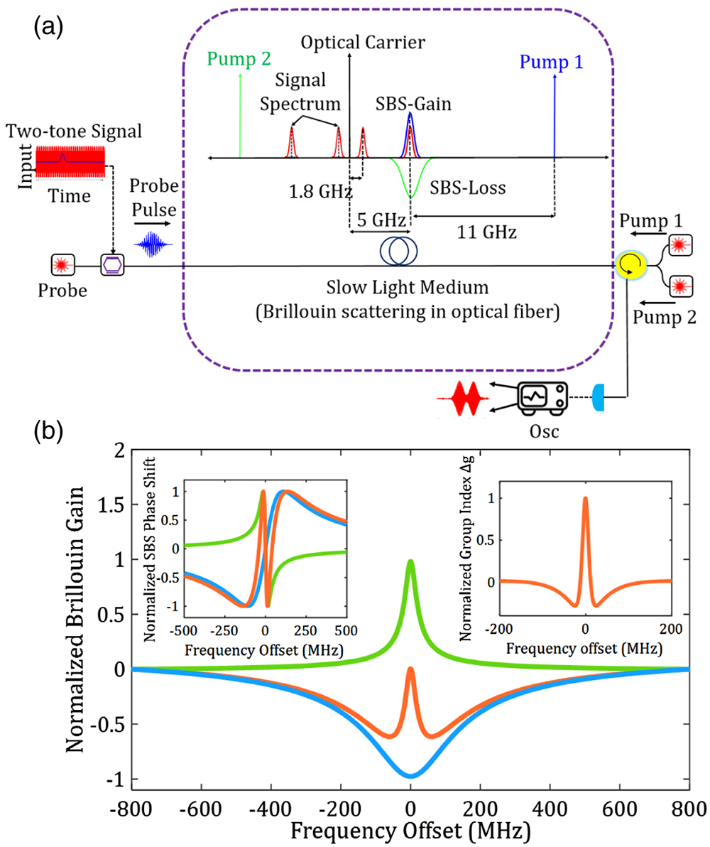
Figure 1.(a) Schematic diagram of the proposed slow light-based spectrum discriminator; (b) simulated Brillouin gain spectrum (green) superimposed with a broad loss (blue), resulting in the orange net curve. The left inset represents the normalized SBS phase response for the gain (green), loss (blue), and the superposed spectrum (orange). The right inset is the corresponding normalized group index change of the superposed Brillouin spectrum.
A spectrum as shown with the orange curve in Fig. 1(b) can be generated from two distinct pump lasers. Since the linewidth of the Brillouin spectrum is a convolution between the natural Brillouin spectrum and the spectrum of the pump wave, the Brillouin linewidth is determined by the pump if its spectrum is much broader. Hence, by direct modulation of the second pump laser, a broadened Brillouin loss spectrum can be obtained. By controlling the optical frequency of the second pump, its loss spectrum can be coincided with the gain spectrum generated from the first pump. As an example, Fig. 2(a) shows two pulses. The red one is delayed by about 20 ns with just the gain and the blue one is the non-delayed pulse. The amplification gain , with as the optical power of the delayed pulse and as that of the reference pulse, measured with the photodiode, is around 20 dB. As can be seen in the inset of Fig. 2(a), the reference and the delayed pulse are not distinguishable from each other. In Fig. 2(b) the BIT was applied for three different delays, resulting in three broadening factors , which are defined as the ratio between the FWHM of the delayed and non-delayed pulse as [17]
![]()
Figure 2.(a) Normalized photodiode output of non-delayed reference pulse (blue) and optical (red) pulse delayed by 20 ns with a conventional Brillouin gain spectrum. The inset shows the zoomed-in section of the reference pulse, completely hidden by the delayed amplified pulse. (b) Measured delayed pulses by a Brillouin spectrum superposed with a broad loss (zero gain).
3. EXPERIMENT
To verify the proposed spectrum sensing technique, an experimental setup as shown in Fig. 3 has been used. The output from a distributed feedback laser (DFB 1) emitting at 1550 nm has been split into an upper and a lower branches to form a probe and Pump 1 wave, respectively. To avoid wavelength drifting and secure high stability between Pump 1 and the probe, both waves have been generated from the same laser source. A pulsed two-tone SUT has been generated in an arbitrary waveform generator by multiplying two RFs and with a Gaussian pulse. In the upper branch, the probe wave was modulated by the optical carrier with the SUT using a Mach–Zehnder intensity modulator (MZM 1) and then passed through to a 10.9 km SSMF. In the lower branch, Pump 1 was used for generating the gain by driving MZM 2 with a continuous-wave RF generator set at . MZM 2 is biased properly to achieve a double sideband suppressed carrier modulation. The lower sideband has been filtered out using a fiber Bragg grating filter. To achieve the required group delay, Pump 1 has been amplified by an erbium-doped fiber amplifier (EDFA 1) to around 8 mW.
![]()
Figure 3.Experimental setup: DFB, distributed feedback laser; AWG, arbitrary waveform generator; RFG, radio frequency generator; MZM, Mach–Zehnder modulator; ISO, isolator; SMF, single-mode fiber; CIR, circulator; FBG, fiber Bragg grating; PC, polarization controller; OC, optical coupler; EDFA, erbium-doped fiber amplifier; PD, photodiode; OSA, optical spectrum analyzer; OSC, oscilloscope; VOA, variable optical attenuator; TC, temperature controller.
The loss (Pump 2) has been generated from another laser source (DFB 2) directly modulated with a Gaussian noise to broaden its spectrum and spectrally placed at through a temperature control. This has been done by monitoring the frequency of the beat note between Pump 2 and Pump 1 via an electrical spectrum analyzer (not shown in the setup). In order to achieve a zero Brillouin gain, the peaks of the gain and loss spectra shall be identical. Since the loss spectrum is broader than the gain spectrum by a factor of , Pump 2 has been amplified by the same factor [31] with EDFA 2. Both pump waves were combined via an optical coupler and directed into the optical fiber through an optical circulator.
4. RESULTS
To measure the superposed Brillouin spectrum, the frequency of the probe wave is scanned in a vicinity of , and the corresponding spectrum is depicted in Fig. 4. To characterize the induced group delay and the broadening of the probe pulses, a Gaussian pulse with an FWHM of 10 ns has been employed as a probe wave.
![]()
Figure 4.Measured superposed Brillouin spectrum, BLS, Brillouin loss spectrum; BGS, Brillouin gain spectrum. The cyan region represents the natural Brillouin spectrum in which the delay takes place.
The fractional delay (), with as the FWHM of the input probe pulses, and the broadening factor of the setup have been measured as a function of the Brillouin gain by changing the pump power and the results are presented in Fig. 5. A small deviation between the experimental and analytical measurements can be observed. This deviation is attributed to some experimental insufficiencies and dispersion in the fiber [17,33]. These characterization curves are used for a broadening compensation.
![]()
Figure 5.Experimental characterization of the (a) pulse broadening and (b) fractional time delay in dependence on the Brillouin gain. The solid curves give the analytical results and the red squares or dots the measured values.
Some useful RF frequency bands have been analyzed to validate the proposed spectrum sensing technique. First, a two-tone RF signal composed of 1.8 and 5 GHz has been tested using the experimental setup in Section 3. Figure 6 shows the measured input RF pulse in the time domain (Pump 1 and Pump 2 are switched off).
![]()
Figure 6.Measured PD output (after dc blocking) of the two-tone (1.8 and 5 GHz) signal before applying the group delay (pump is off). The inset is the corresponding measured RF spectrum.
The photodiode measures the optical power. However, for all measurements an additional optical power bias was adjusted at the modulator, so that after subtracting this bias, positive and negative components seem to occur.
For the proof-of-concept, the input power of both frequency components has been set equally. However, this is not necessary for the proposed technique. In the first experiment, the higher-frequency component has been delayed against the lower one. To achieve a high separation between the two frequencies, a fractional delay of around 2 has been adjusted and the result can be seen in Fig. 7. To verify the configurability of the proposed scheme, the lower-frequency component (i.e., 1.8 GHz) has been delayed against the higher one. This is obtained by properly tuning the wavelengths of Pumps 1 and 2 to make the Brillouin spectra coincide with the RF spectrum at 1.8 GHz. As can be seen in Figs. 8(a) and 8(b), the input RF spectra are again separated by 20 ns and the 1.8 GHz frequency component appears later. Additionally, we have considered another frequency combination of 5 and 0.9 GHz. Using the same approach with putting the SBS-induced delay profile at 5 GHz, again both frequency components have been discriminated, as presented in Figs. 8(c) and 8(d). Furthermore, in all cases we observed that the input two-tone RF signal is properly resolved in time which enables additional real-time post-processing.
![]()
Figure 7.(a) Output RF signal (after dc removal) for the delay of the 5 GHz signal after broadening compensation and amplitude normalization. The inset shows the raw data before compensation. (b) Spectrogram (time–frequency mapping) of the output signal in (a).
![]()
Figure 8.(a) Output RF signal (after dc removal) for delaying the 1.8 GHz signal against the 5 GHz; (b) spectrogram of the output signal in (a); (c) separation between 5 GHz and 0.9 GHz signals (5 GHz is delayed); and (d) spectrogram of the output signal in (c).
5. DISCUSSION
Many advanced real-world applications require that the spectral information of the signal under test is provided and captured in a real-time dynamic manner. This involves the capability of detecting and tracking fast dynamics of the frequency information in the SUT continuously in real time [14]. For the proposed method, an offline post-processing or analysis of the signal is not necessary. However, fast dynamic changes can only be measured if they are slower than the repetition time of the pulses required for carving out pulses from the spectrum. Additionally, the method is just able to detect if a given, pre-defined frequency band is occupied or not. For the measurement of other frequency ranges, the pump waves have to be tuned, or other pre-defined pump wavelengths have to be switched on and off. The latency associated with the fiber length can be optimized by selecting shorter fibers, while increasing the pump power to achieve the same group delay, or by integrating the system on a chip.
To achieve a large group delay via SBS, a significant group index change is required which in turn requires a large Brillouin gain (), where is the SBS medium length and is the speed of light. To date, various high-gain, on-chip SBS schemes have been demonstrated. In an optimized chalcogenide ()-on-silica waveguide a 52 dB SBS gain has been demonstrated for instance [34]. In another work, on-chip SBS slow light with a group delay of 23 ns has been reported in a 7 cm long rib waveguide based on platform [35]. Thus, the proposed method can be straight forwardly integrated into existing SBS chips.
In principle the proposed method can identify more than two radio frequencies. Different frequency components can be detected with different pump waves and different amplitudes, resulting in different group delays. However, the number of frequency components that can be distinguished depends on the maximum delay and the broadening of the pulses. The maximum delay that can be achieved by this method is around 3 times the pulse width [26]. So, at least three frequencies can be distinguished. This might be enhanced by an accurate compensation of the broadening. For a broadened gain superimposed with a loss the maximum fractional delay is around 3 bits [26]. For the experiment we have chosen 10 ns pulses with a bandwidth of around 100 MHz. The gain bandwidth is around 30 MHz and the loss 210 MHz. The 30 MHz broad frequency range in the middle of the pulse spectrum will be delayed by 20 ns, whereas the edges would see an advancement (see Fig. 4). However, since the bandwidth of the loss is much broader than that of the pulse, the frequency components at the edges will be strongly attenuated. Hence, only the delayed part can be seen at the output. But this carving out of frequency components will lead to a broadening of the pulses. In principle the duration, time delay, and broadening factor in the experiment were chosen in a way that the delay can be clearly seen.
The specification of 5G supports bandwidths ranging from 5 MHz to 100 MHz for bands below 6 GHz [36,37]. Thus, the bandwidth of the signal and data channels in 5G is usually broader than the gain bandwidth of SBS (10–30 MHz). However, the proposed method just detects if there is a frequency component in the SBS gain bandwidth or not. As long as a signal component (the carrier, for instance) falls into the gain spectrum of SBS, there will be a delayed pulse. If the carrier (and no other frequency components in the range of 10–30 MHz around the carrier) is not present, no delayed pulse can be seen. For signal spectra with widths up to the loss bandwidth (210 MHz), just the delayed pulse will be present at the output since the frequency components outside the gain bandwidth will be strongly attenuated (see Fig. 4). If the signal bandwidth is broader than the loss bandwidth, there will be a delayed and a non-delayed pulses, since the frequency components of the signal outside the loss bandwidth propagate with the normal group velocity along the waveguide. If necessary, however, the gain and loss bandwidths can be adapted to the signal spectrum by a modulation [22].
The SBS gain spectrum is downshifted from the pump wave by the Brillouin frequency shift of the fiber, which is around 11 GHz in the single-mode fiber at 1550 nm pump wavelength. Therefore, the absolute frequency of the resolved RF signals can be precisely determined. However, the Brillouin frequency shift of a fiber depends on strain and temperature, so the SBS frequency shift of the fiber has to be measured first and during the measurement the temperature and strain have to be kept constant.
6. CONCLUSIONS
In this work, we have presented a novel approach for real-time spectrum sensing based on Brillouin-scattering-induced transparency. The gain associated with the Brillouin-induced delay has been optically compensated by superposing it with a broad Brillouin loss spectrum. In the proof-of-concept demonstration, a fractional delay of around 2 has been used to temporally resolve two pairs of frequencies (5, 0.9 GHz) and (5, 1.8 GHz). The proposed method can be implemented using low-cost conventional optical and electrical components without employing any DSP-based offline signal processing unit. Time-resolved RF components can be detected by using a low-bandwidth photodiode and an oscilloscope. The system is fully reconfigurable by tuning two pump waves and can be integrated on SBS compatible platforms. Due to its agile, fast processing, and high resolution, the proposed technique is a promising solution for real-time spectrum sensing of 5G and mm-wave signals.
Acknowledgment
Acknowledgment. The authors would like to acknowledge Dr. Stefan Preussler, Karanveer Singh, and Janosch Meier from Technische Universität Braunschweig for the fruitful discussions. Open access publication received funding from Technische Universität Braunschweig.
References
[1] C. R. Stevenson, G. Chouinard, Z. Lei, W. Hu, S. J. Shellhammer, W. Caldwell. IEEE 802.22: the first cognitive radio wireless regional area network standard. IEEE Commun. Mag., 47, 130-138(2009).
[2] R. Das, T. Schneider. Integrated group delay units for real-time reconfigurable spectrum sensing of mm-wave signals. Opt. Lett., 45, 4778-4781(2020).
[3] LAN/Man Committee. Part 22: Cognitive Wireless RAN Medium Access Control (MAC) and Physical Layer (PHY) Specifications: Policies and Procedures for Operation in the TV Bands, 1-680(2011).
[4] X. Zou, B. Lu, W. Pan, L. Yan, A. Stöhr, J. Yao. Photonics for microwave measurements. Laser Photonics Rev., 10, 711-734(2016).
[5] M. Burla, X. Wang, M. Li, L. Chrostowski, J. Azanã. Wideband dynamic microwave frequency identification system using a low-power ultracompact silicon photonic chip. Nat. Commun., 7, 13004(2016).
[6] Q. Zhang, D. L. Sounas, C. Caloz. Synthesis of cross-coupledreduced-order dispersive delay structures (DDSS) with arbitrary group delay and controlled magnitude. IEEE Trans. Microwave Theory Tech., 61, 1043-1052(2013).
[7] S. Gupta, Q. Zhang, L. Zou, L. J. Jiang, C. Caloz. Generalized coupled-line all-pass phasers. IEEE Trans. Microwave Theory Tech., 63, 1007-1018(2015).
[8] M. Z. Chen, Q. Cheng, F. Xia, A. K. Rashid, J. Y. Dai, C. Zhang, Q. Zhang, T. J. Cui. Metasurface‐based spatial phasers for analogue signal processing. Adv. Opt. Mater., 8, 2000128(2020).
[9] A. Choudhary, B. Morrison, I. Aryanfar, S. Shahnia, M. Pagani, Y. Liu, K. Vu, S. Madden, D. Marpaung, B. J. Eggleton. With giant on-chip Brillouin gain. J. Lightwave Technol., 35, 846-854(2017).
[10] D. Marpaung, J. Yao, J. Capmany. Integrated microwave photonics. Nat. Photonics, 13, 80-90(2019).
[11] T. Jannson. Real-time Fourier transformation in dispersive optical fibers. Opt. Lett., 8, 232-234(1983).
[12] J. Azaña, M. A. Muriel. Real-time optical spectrum analysis based on the time-space duality in chirped fiber gratings. IEEE J. Quantum Electron., 36, 517-525(2000).
[13] L. Cohen. Time-frequency distributions: a review. Proc. IEEE, 77, 941-981(1989).
[14] S. R. Konatham, R. Maram, L. R. Cortés, J. H. Chang, S. LaRusch, S. Rochelle, H. G. de Chatellus, J. Azaña. Real-time gap-free dynamic waveform spectral analysis with nanosecond resolutions through analog signal processing. Nat. Commun., 11, 3309(2020).
[15] S. R. Konatham, H. G. De Chatellus, J. Azana. Photonics-based real-time spectrogram analysis of broadband waveforms. J. Lightwave Technol., 38, 5356-5367(2020).
[16] R. Boyd. Nonlinear Optics(2008).
[17] Z. Zhu, D. J. Gauthier, Y. Okawachi, J. E. Sharping, A. L. Gaeta, R. Boyd, A. E. Willner. Numerical study of all-optical slow-light delays via stimulated Brillouin scattering in an optical fiber. J. Opt. Soc. Am. B, 22, 2378-2384(2005).
[18] S. Preussler, T. Schneider. Stimulated Brillouin scattering gain bandwidth reduction and applications in microwave photonics and optical signal processing. Opt. Eng., 55, 031110(2015).
[19] S. Preussler, A. Wiatrek, K. Jamshidi, T. Schneider. Brillouin scattering gain bandwidth reduction down to 3.4 MHz. Opt. Express, 19, 8565-8570(2011).
[20] S. Preussler, T. Schneider. Bandwidth reduction in a multistage Brillouin system. Opt. Lett., 37, 4122-4124(2012).
[21] A. Wiatrek, S. Preussler, K. Jamshidi, T. Schneider. Frequency domain aperture for the gain bandwidth reduction of stimulated Brillouin scattering. Opt. Lett., 37, 930-932(2012).
[22] T. Schneider, M. Junker, K. Lauterbach. Potential ultra wide slow-light bandwidth enhancement. Opt. Express, 14, 11082-11087(2006).
[23] K. Y. Song, M. G. Herráez, L. Thévenaz. Observation of pulse delaying and advancement in optical fibers using stimulated Brillouin scattering. Opt. Express, 13, 82-88(2005).
[24] M. G. Herráez, K. Y. Song, L. Thévenaz. Optically controlled slow and fast light in optical fibers using stimulated Brillouin scattering. Appl. Phys. Lett., 87, 081113(2005).
[25] T. Schneider, R. Henker, K. Lauterbach, M. Junker. Comparison of delay enhancement mechanisms for SBS-based slow light systems. Opt. Express, 15, 9606-9613(2007).
[26] T. Schneider. Time delay limits of stimulated-Brillouin-scattering-based slow light systems. Opt. Lett., 33, 1398-1400(2008).
[27] T. Schneider, R. Henker, K. Lauterbach, M. Junker. Distortion reduction in slow light systems based on stimulated Brillouin scattering. Opt. Express, 16, 8280-8285(2008).
[28] A. Wiatrek, R. Henker, S. Preussler, T. Schneider. Pulse broadening cancellation in cascaded slow-light delays. Opt. Express., 17, 7586-7591(2009).
[29] T. Schneider, A. Wiatreck, R. Henker. Zero-broadening and pulse compression slow light in an optical fiber at high pulse delays. Opt. Express, 16, 15617-15622(2008).
[30] A. Minardo, R. Bernini, L. Zeni. Low distortion Brillouin slow light in optical fibers using AM modulation. Opt. Express, 14, 5866-5876(2006).
[31] S. Chin, M. G. Herráez, L. Thévenaz. Zero-gain slow & fast light propagation in an optical fiber. Opt. Express, 14, 10684-10692(2006).
[32] T. Schneider, M. Junker, K. Lauterbach. Time delay enhancement in stimulated-Brillouin-scattering-based slow-light systems. Opt. Lett., 32, 220-222(2007).
[33] Y. Okawachi, J. E. Sharping, A. L. Gaeta, M. S. Bigelow, A. Schweinsberg, R. W. Boyd, Z. Zhu, D. J. Gauthier. Tunable all-optical delays via Brillouin slow light in an optical fiber. Conference on Lasers and Electro-Optics/Quantum Electronics and Laser Science and Photonic Applications Systems Technologies, CMCC3(2005).
[34] A. Choudhary, Y. Liu, D. Marpaung, B. J. Eggleton. On-chip Brillouin filtering of RF and optical signals. IEEE J. Sel. Top. Quantum Electron., 24, 7600211(2018).
[35] R. Pant, A. Byrnes, C. G. Poulton, E. Li, D.-Y. Choi, S. Madden, B. Luther-Davies, B. J. Eggleton. On-chip slow and fast light using stimulated Brillouin scattering. Opt. Lett., 37, 969-971(2012).
[36] C. X. Wang, J. Bian, J. Sun, W. Zhang, M. Zhang. A survey of 5G channel measurements and models. Commun. Surveys Tuts., 20, 3142-3168(2018).

Set citation alerts for the article
Please enter your email address
© Copyright 2018-2021 | Chinese Laser Press. All Rights Reserved 沪ICP备15018463号-20