• Chinese Optics Letters
  • Vol. 19, Issue 9, 093701 (2021)
Shitong Xu1、*, Fei Fan2, Hongzhong Cao1, Yinghua Wang1, and Shengjiang Chang2、3
Author Affiliations
  • 1Shandong Provincial Key Laboratory of Laser Polarization and Information Technology, Department of Physics, School of Physics and Engineering, Qufu Normal University, Qufu 273165, China
  • 2Institute of Modern Optics, Tianjin Key Laboratory of Micro-Scale Optical Information Science and Technology, Nankai University, Tianjin 300350, China
  • 3Tianjin Key Laboratory of Optoelectronic Sensor and Sensing Network Technology, Tianjin 300350, China
  • show less
    DOI: 10.3788/COL202119.093701 Cite this Article Set citation alerts
    Shitong Xu, Fei Fan, Hongzhong Cao, Yinghua Wang, Shengjiang Chang. Liquid crystal integrated metamaterial for multi-band terahertz linear polarization conversion[J]. Chinese Optics Letters, 2021, 19(9): 093701 Copy Citation Text show less
    Structure diagram of the liquid crystal integrated metal grating (LCMG) under the constant M-field and variable E-field (B∥x, E∥z); the coordinate axis is attached to the right. The diagram of LC orientation in the LCMG when (a) E E E > 20 kV/m.
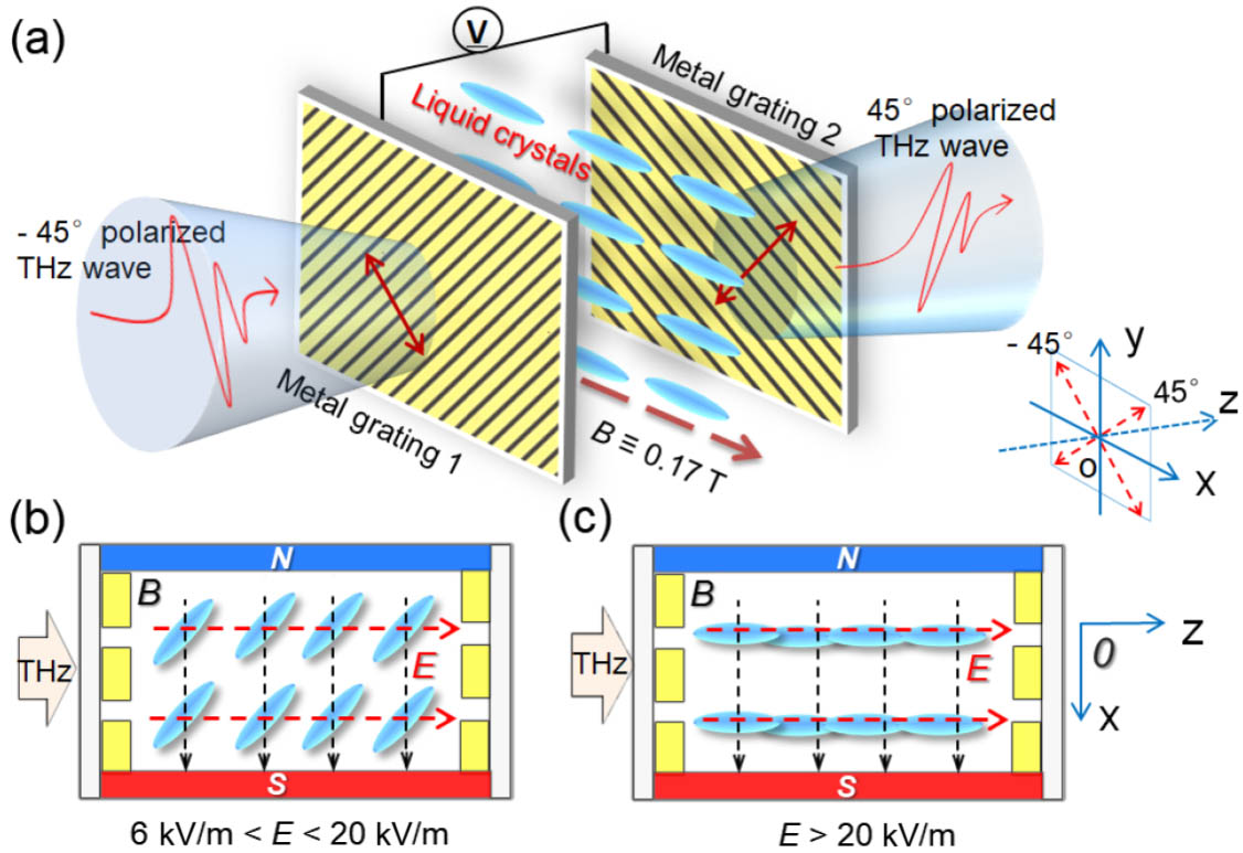
    Fig. 1. Structure diagram of the liquid crystal integrated metal grating (LCMG) under the constant M-field and variable E-field (Bx, Ez); the coordinate axis is attached to the right. The diagram of LC orientation in the LCMG when (a) E < 6 kV/m; (b) 6 kV/m < E < 20 kV/m; (c) E > 20 kV/m.
    (a) Experimental light path of the THz-TDS system; the sample is placed in a 3D-printed mold with a set of permanent magnets, and the E-field is applied by the connected wires. The experimentally measured (b) time-domain signals and (c) refractive index of the LC with 90° and 0° orientations under the E-field of 0 and 20 kV/m. (d) The experimental and simulative transmission of the metal grating at TM and TE polarization modes.
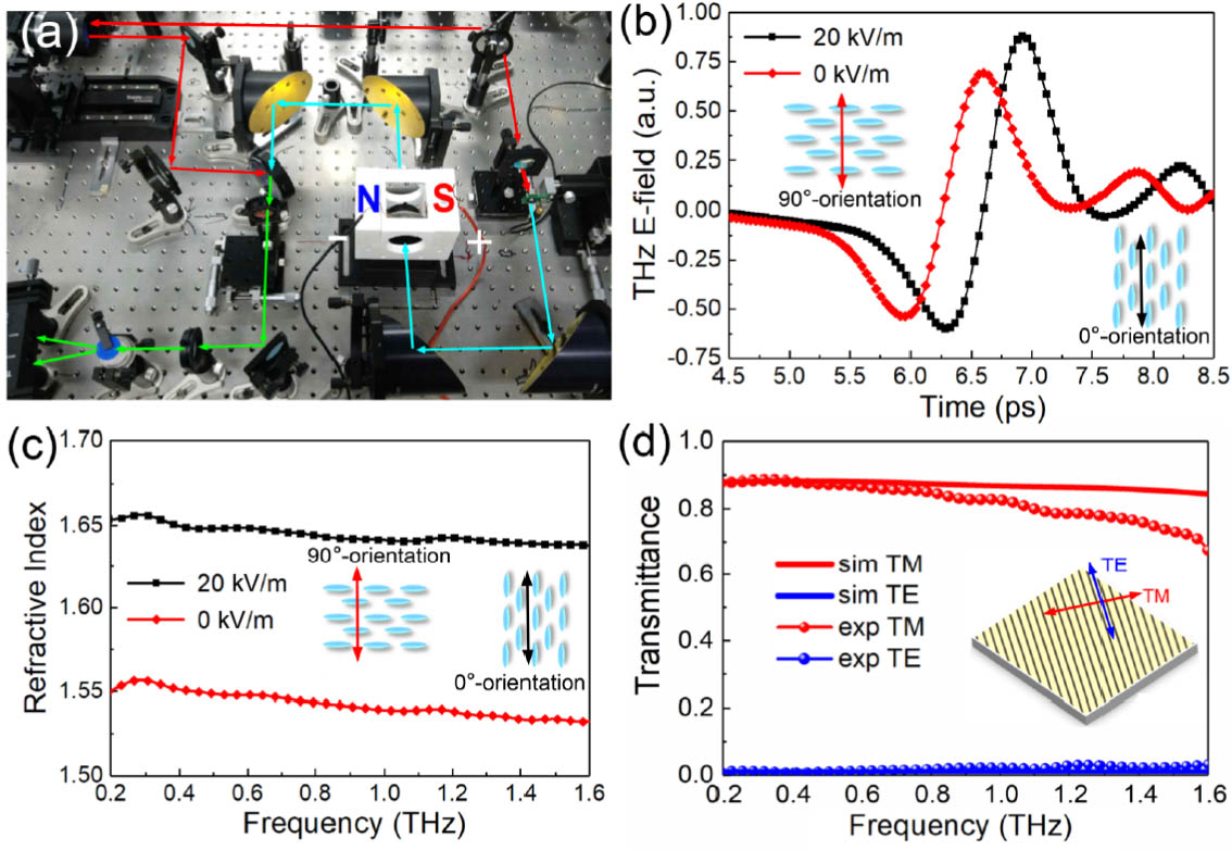
    Fig. 2. (a) Experimental light path of the THz-TDS system; the sample is placed in a 3D-printed mold with a set of permanent magnets, and the E-field is applied by the connected wires. The experimentally measured (b) time-domain signals and (c) refractive index of the LC with 90° and 0° orientations under the E-field of 0 and 20 kV/m. (d) The experimental and simulative transmission of the metal grating at TM and TE polarization modes.
    Experimental (a) time-domain signals and (b) transmission spectra of the LCMG when the E-fields increase from 0 to 20 kV/m. (c) The diagrams of the effective refractive index (neff) ellipsoids of the LC with the E-field at 0–6 kV/m, 6–20 kV/m, and 20 kV/m. (d) The simulated transmittance spectra when the LC molecules are orientated with different angles to the coordinate axis.
    Fig. 3. Experimental (a) time-domain signals and (b) transmission spectra of the LCMG when the E-fields increase from 0 to 20 kV/m. (c) The diagrams of the effective refractive index (neff) ellipsoids of the LC with the E-field at 0–6 kV/m, 6–20 kV/m, and 20 kV/m. (d) The simulated transmittance spectra when the LC molecules are orientated with different angles to the coordinate axis.
    Polarization evolution in the LCMG when the LC layer is in the (a) x and (b) z orientations.
    Fig. 4. Polarization evolution in the LCMG when the LC layer is in the (a) x and (b) z orientations.
    Distribution of the E-vector at the (a) input plane, (b) middle plane, and (c) output plane of the x−y cutting view in the LCMG when the LC layer is in the x orientation at 0.78 THz. The arrows indicate the direction of the THz polarization. The y−z cutting plane of E-vector distributions in the LCMG when the LC layer is in the (d) x orientation or (e) z orientation.
    Fig. 5. Distribution of the E-vector at the (a) input plane, (b) middle plane, and (c) output plane of the x−y cutting view in the LCMG when the LC layer is in the x orientation at 0.78 THz. The arrows indicate the direction of the THz polarization. The y−z cutting plane of E-vector distributions in the LCMG when the LC layer is in the (d) x orientation or (e) z orientation.
    (a) Working principle diagram of the unidirectional transmission in the LCMG. (b) The extinction ratios of unidirectional transmission; the experimental and simulated data are represented by the dotted line and straight line, respectively.
    Fig. 6. (a) Working principle diagram of the unidirectional transmission in the LCMG. (b) The extinction ratios of unidirectional transmission; the experimental and simulated data are represented by the dotted line and straight line, respectively.
    E-Field Experiments0 V6 V8 V10 V12 V20 V
    θ (fitted)35°48°60°70°90°
    neff (nx,y,z) (simulated)1.65,1.61,1.59,1.57,1.56,1.55,
    1.55,1.55,1.55,1.55,1.55,1.55,
    1.551.581.601.621.631.65
    Table 1. Detailed Parameters of Simulated LC Refractive Index Ellipsoid with Different Orientation Angles θ and External E-Field
    Shitong Xu, Fei Fan, Hongzhong Cao, Yinghua Wang, Shengjiang Chang. Liquid crystal integrated metamaterial for multi-band terahertz linear polarization conversion[J]. Chinese Optics Letters, 2021, 19(9): 093701
    Download Citation