
Chao Tan, Linjie Zhao, Mingjun Chen, Jian Cheng, Zhaoyang Yin, Qi Liu, Hao Yang, Wei Liao. Combined studies of surface evolution and crack healing for the suppression of negative factors during CO2 laser repairing of fused silica[J]. Chinese Optics Letters, 2021, 19(4): 041402
- Chinese Optics Letters
- Vol. 19, Issue 4, 041402 (2021)
Abstract
1. Introduction
Fused silica optics are widely used in terminal optical components of high-power laser devices due to their excellent optical characteristics and process performance. However, UV laser-induced damage to the surface of fused silica inevitably occurs, and the size of the damage pit increases exponentially in subsequent laser irradiation, which seriously affects the stability of optical components and limits the output flux of large high-power solid-state laser devices[
Research at home and abroad shows that the non-evaporative repairing method of laser local irradiation can greatly suppress the growth of surface damage of fused silica optics[
Feit et al. first proposed the theoretical models of heat conduction, melt flow, evaporation, and gasification in the laser repairing process. He pointed out that the recoil pressure generated by the evaporation of the material and the healing of the crack at the bottom of the damage pit might affect the surface quality of the repaired site[
Sign up for Chinese Optics Letters TOC. Get the latest issue of Chinese Optics Letters delivered right to you!Sign up now
It can be concluded that the research at this stage is more focused on the experimental studies of the mitigation process improvement and repairing effect evaluation, as well as the calculation and analysis using the single mathematical model. There is no systematic study on the phase transition kinetics of the material, the evolution of surface morphology, and the process of crack healing. However, these are the key to revealing the formation mechanism of the negative factors in the laser repair process and seeking methods to suppress these factors.
In this Letter, the physical problems (e.g., heat and mass transfer, material phase transition, melt flow, evaporation removal, crack healing, cooling, and freezing) involved in the process of laser repairing surface damage of fused silica optics are analyzed through numerical simulation and experimental methods. In order to reveal the evolution mechanism of repaired morphology and the material migration mechanism on the crack surface, two multi-physics coupling mathematical models with different scales are developed, respectively. The models include the material’s behaviors of melt flow and evaporation and consider the internal effects of Marangoni, gravity, capillary force, and gasification recoil pressure. Combined with the experimental research, the methods to suppress the negative factors, such as the raised edge around the repaired site and the formation of bubbles, are proposed.
2. Theory and Model
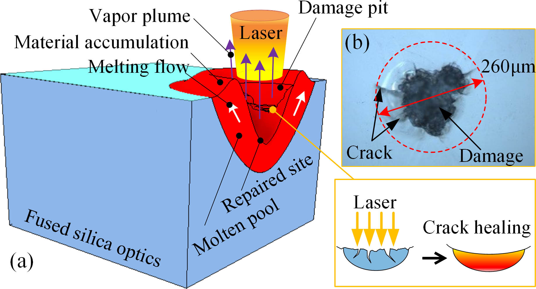
The schematic diagram of non-evaporative laser repairing of fused silica surface damage is shown in Fig. 1. Figure 1(b) is the original damage pit on the surface of the fused silica optics measured by the optical microscope (Nikon ECLIPSE E600). The damage pit has the diameter of about 260 µm and the depth of about 60 µm. Cracks of various sizes are distributed at the bottom of the damage pit. When the CW laser acts on the surface, the substrate temperature gradually increases. As the center temperature exceeds the melting point of fused silica, the material at the center of the damage pit gradually melts, forming a molten pool. With the increasing of the laser irradiation time, the molten pool gradually expands to the inside of the bulk, and the molten material begins to flow outwards under the action of the Marangoni effect and capillary force. When the substrate temperature exceeds the evaporation temperature, part of the material is evaporated and ablated. At the same time, the gasification recoil pressure formed by the outward splashing of the vapor plume acts on the surface of the molten pool, which prompts a large amount of molten material to flow outwards and gradually accumulate on the edge to form the raised rim. Additionally, the material’s melting flow can heal the cracks at the damage pit, and the repaired site with smooth surface morphology is formed eventually. When the laser is off, the substrate temperature decreases instantly, and the molten pool disappears in a short time. The material structure of the repaired site region is modified by the thermal effect of the laser.
![]()
Figure 1.Schematic diagram of the non-evaporative laser repairing of fused silica surface damage. (a)
Since the size range of the micro-cracks around the damage pit is quite different from the scale of the surface damage, the separate models are used to analyze the repairing morphology evolution and crack healing behavior in this work. The thermodynamic and dynamic behaviors of material in the process of laser interaction with fused silica can be solved by the conservation equations of mass, momentum, and energy, which can be described as
For material flow in the molten pool, the freely deformable surface is mainly affected by surface tension, in which the thermal capillary force (Marangoni effect) acts in the tangential direction, and its size is related to the temperature gradient. While the capillary force acts in the normal direction, its size is proportional to the curvature of the surface profile. They can be expressed as[
When evaporative ablation occurs, part of the laser heat can be taken away by the material escaping outwards, which can be defined as[
The mathematical model of this work considers the variations of physical properties of fused silica with respect to temperature, such as thermal conductivity, heat capacity, and dynamic viscosity. The selection of relevant parameters has been published in previous work[
3. Results and Discussions
The morphology evolution and phase transition processes under the irradiation of lasers with different powers are shown in Fig. 2. The laser used is a 10.6 µm CW laser, with a spatial Gaussian distribution with a spot diameter of 2 mm at . The laser power is set to 30 W, 31 W, and 32 W in sequence, and the action time is 5 s.
![]()
Figure 2.Surface morphology evolutions and phase transition processes of fused silica optics irradiated by
In the heating stage, the material in the molten pool flows outwards under the combined action of Marangoni effect, gravity, and capillary force, of which the Marangoni effect plays a promoting role, while the capillary force acts as an obstacle. When the center material is vaporized and ablated, certain ablation morphology is formed, and the gasification recoil pressure acts on the upper surface of the molten pool. Its value is much greater than the thermal capillary force and capillary force, which prompts the material to flow further to the outside and gradually accumulate at the edge of the molten pool to form the Gaussian crater morphology with raised rim feature, as shown in Figs. 2(a), 2(c), and 2(e). As the laser power increases, the material ablation degree and the gasification recoil pressure increase, and the depth of the Gaussian crater and height of the protrusion become larger and larger. It can be obtained that the gasification recoil pressure is the leading factor in the formation of the Gaussian crater with raised features. When the laser is off, the substrate temperature and the molten pool area temperature decrease rapidly within 0.1 s, as shown in Figs. 2(b), 2(d), and 2(f). The molten material on the raised edge has a tendency to reflow under the action of capillary force; however, it cannot change the final surface morphology because of its small value. It can be seen that the area of the remaining molten pool at the same moment increases as the laser power rises, and the material reflow tendency in this area becomes more obvious. The height of the raised rim has reached 30 µm at the laser power of 32 W, which will cause strong optical modulation and should be strictly controlled.
Figure 3 shows the repaired morphologies obtained by experiments of different laser powers. It is necessary to create a damage pit on the surface of the polished Corning 7980 fused silica glass sample (50 mm length, 50 mm width, 5 mm thickness) before the experiment. The laser power used for repairing is 30 W, 31 W, and 32 W, and the laser irradiation time is 5 s. The right side of the experimental morphology in Fig. 3 is the calculated morphology and surface temperature distribution under the same condition.
![]()
Figure 3.
It can be seen from the repaired morphology in Fig. 3 that there are bright circular rings and redeposited debris around the repaired crater, which indicates that material evaporation occurs, and the raised rim feature is formed on the edge in the actual laser repairing process. The greater the laser power, the more severe the material ablation, and the more pronounced the raised rim. It shows that the material’s evaporative ablation is the leading factor in the formation of the raised feature, which is consistent with the conclusion obtained from the simulation shown in Fig. 2. Since the redeposited debris distributed around the repaired crater will enhance the absorption of light, reasonable laser power and irradiation time should be selected to avoid material ablation in the actual non-evaporative laser repairing process. On the other hand, certain measures can be taken to eliminate these negative factors, such as use of suction device and large spot passivation[
Since there are many various cracks at the bottom of the damage pit, the crack healing process, bubble formation mechanism, and its control method during laser repairing will be analyzed below. The schematic diagram of the crack healing process is shown in Fig. 4(a). The diameter of the laser irradiation area above the crack is 10 µm, and the laser power density is the same as the Gaussian spot with the power of 30 W and the diameter of 2 mm at . The crack healing time and the thickness of the healing area can be approximated by the following formula[
![]()
Figure 4.Evolution process of crack morphology under laser action.
Figures 4(b)–4(d) show the evolution process of crack morphology under the action of the laser. Due to the large variation range of the actual crack depth size (from a few microns to hundreds of microns), considering the sizes of the geometric model and the laser spot, the crack depth is set to 20 µm, and the width is 0.3 µm. When the laser acts on the crack surface, the surface material gradually melts to form a molten pool. The material in the molten pool melts and flows under the effects of Marangoni, capillary force, and gravity, and the top of the crack first closes inwards, as shown in Fig. 4(b). As the laser action time increases, the molten pool gradually expands into the bulk, and the melt flow rate increases. The entire crack is in the liquid phase region at around 3 s, as shown in Fig. 4(c). The crack gradually heals from the top to the bottom until the morphology of the crack surface no longer changes with the increase of laser action time, as shown in Fig. 4(d). From the partially enlarged view of the crack morphology in Fig. 4(d), it can be seen that, although the molten pool continuously expands inwards with the increase of the laser action time, there is always an air interlayer with the length of 10 µm and the width of 0.15 µm at the bottom of the crack. This air layer is due to the fact that, when the laser with the power of 30 W equivalently acts on the crack surface, the material at the top of the crack heals first, and the air inside the crack is too late to escape. It corresponds to the formation of bubbles during the actual repairing process. The larger the size of the residual air layer after the crack heals, the larger the bubble formed.
The size of the residual air layer inside the crack irradiated by the laser of different powers is shown in Fig. 5. The action time in the figure is the time from the start of laser irradiation until the crack morphology no longer changes. It can be seen that when the laser power increases from 30 W to 40 W, the width of the air layer increases from 0.15 µm to 0.24 µm, and the length increases from 10 µm to 16 µm. When the laser power is 20 W with the action time of 10 s, the width and length of the air layer after the crack healing are only 0.05 µm and 1 µm. This is because different from the way of crack healing from top to bottom under the action of the high-power laser, the use of a low-power laser for a long time can fully melt the material around the crack before healing, which greatly reduces the size of the residual air layer.
![]()
Figure 5.Size of the residual air layer inside the crack irradiated by the laser of different powers.
It can be concluded from the above analysis that when the high-power laser is used to repair surface damage directly, it is easy to form large bubbles due to the uneven heating of the material in the damage pit. Therefore, in order to suppress the formation of bubbles, the low-power laser is recommended to irradiate the damage pit first for fully preheating the material and prompting the air inside the crack to escape, and then the high-power laser is used to repair it immediately afterwards. The following two different schemes are used to repair the damage pits with the lateral size of about 300 µm and the depth of about 60 µm. In scheme I, the laser power is set to 11 W for 40 s, then 14 W for 20 s, and finally 27 W for 5 s. Scheme II directly uses the laser with power of 27 W for 5 s. The repairing results of the two schemes are shown in Fig. 6.
![]()
Figure 6.Repairing results of two processing schemes. (a) and (d) are the initial surface damage morphologies; (b) and (c) are the repairing results of scheme I; (e) and (f) are the repairing results of scheme II.
The mitigation effect with scheme I is better, as shown in Figs. 6(a)–6(c). It can be seen that only one bubble with the diameter of about 9 µm is formed. The bubble of this size will not affect the damage threshold of the fused silica optics. While after repairing with scheme II, a large number of bubbles appear below the repaired surface, as shown in Figs. 6(d)–6(f), most of which are around 10 µm. In the enlarged view, a bubble with the size of 62 µm can be seen. These large numbers of small bubbles are left by many tiny cracks when they are quickly closed at a higher temperature, and the larger-shaped bubbles are formed by deeper cracks. These two types of bubbles should be avoided during the laser repairing process.
The presence of bubbles in the laser repairing process has a great impact on the ability of resistance to laser damage of fused silica optics. It can be drawn from the experimental test results that the more bubbles and the denser the bubbles, the lower the damage threshold. In order to better control the number of bubbles, it is necessary to optimize the processing parameters during the laser repairing process. The correlations between bubble, crack size, and laser parameters will be further studied in the future.
4. Conclusion
In summary, the physical problems in the process of laser repairing surface damage of fused silica optics were studied, including heat and mass transfer, material phase transition, melt flow, evaporation removal, crack healing, cooling, and freezing. The evolution mechanism of repairing morphology and the material migration mechanism of the crack surface were revealed. Studies have shown that material ablation during the laser repairing process and the gasification recoil pressure accompanying the material splashing were the leading factors in forming the Gaussian repaired morphology with raised rim features. The molten material in the cooling stage tended to flow back under the action of capillary force. Furthermore, the use of a low-power laser for a long time can fully melt the material around the crack and prompt the air inside to escape before healing, which could greatly reduce the size of the residual air layer. On the basis of the above research, the methods to suppress the negative factors (e.g., raised rim, deposited debris, and air bubbles) in the laser repairing process were proposed.
References
[8] T. Doualle, L. Gallais, S. Monneret, S. Bouillet, A. Bourgeade, C. Ameil, L. Lamaignère, P. Cormont. Development of a laser damage growth mitigation process, based on CO2 laser micro processing, for the Laser MegaJoule fused silica optics. Proc. SPIE, 10014, 2016.
[17] R. M. Brusasco, B. Penetrante, J. A. Butler, L. W. Hrubesh. Localized CO2 laser treatment for mitigation of 351-nm damage growth in fused silica. Proc. SPIE, 4679, 40(2002).
[18] M. D. Feit, A. M. Rubenchik. Mechanisms of CO2 laser mitigation of laser damage growth in fused silica. Proc. SPIE, 4932, 91(2004).
[19] G. Guss, I. Bass, V. Draggoo, R. Hackel, S. Payne, M. Lancaster, P. Mak. Mitigation of growth of laser initiated surface damage in fused silica using a 4.6-micron wavelength laser. Proc. SPIE, 6403, 64030M(2007).
[22] L. J. Zhang, C. C. Zhang, J. Chen, Y. Bai, Y. L. Jiang, X. L. Jiang, H. J. Wang, X. Y. Luan, X. D. Yuan, W. Liao. Formation and control of bubbles during the mitigation of laser-induced damage on fused silica surface. Acta Phys. Sin., 67, 016103(2018).
[24] I. L. Bass, G. M. Guss, M. J. Nostrand, P. J. Wegner. An improved method of mitigating laser-induced surface damage growth in fused silica using a rastered, pulsed CO2 laser. Proc. SPIE, 7842, 784220(2010).

Set citation alerts for the article
Please enter your email address
© Copyright 2018-2021 | Chinese Laser Press. All Rights Reserved 沪ICP备15018463号-20