• Advanced Photonics
  • Vol. 3, Issue 2, 026002 (2021)
Adam Overvig1 and Andrea Alù1、2、*
Author Affiliations
  • 1City University of New York, Advanced Science Research Center, Photonics Initiative, New York, United States
  • 2City University of New York, Graduate Center, Physics Program, New York, United States
  • show less
    DOI: 10.1117/1.AP.3.2.026002 Cite this Article Set citation alerts
    Adam Overvig, Andrea Alù. Wavefront-selective Fano resonant metasurfaces[J]. Advanced Photonics, 2021, 3(2): 026002 Copy Citation Text show less
    Spin, spectral, and spatial selectivity in Fano metasurfaces. (a) A conventional Fano resonant metasurface with spectral and angular selectivity supports a band-edge mode that is maximally Fano resonant for x polarized light at normal incidence. (b) When an arbitrary wavefront is incident on it, no distinct spectral feature can be found, and the wave is primarily transmitted with little distortion. In this case, the band-edge mode is not excited. (c) Proposed metasurface with spin, spectral, and spatial selectivity, yielding a band-edge mode maximally Fano resonant for RCP light with a specifically tailored wavefront. (d) When an arbitrary plane wave is incident, no distinct spectral feature can be observed, and light is primarily transmitted with little distortion.
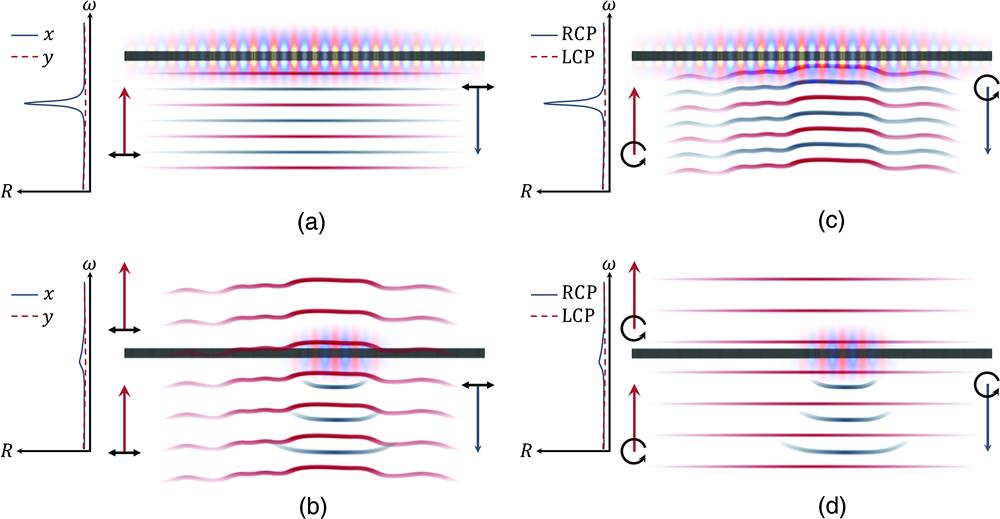
    Fig. 1. Spin, spectral, and spatial selectivity in Fano metasurfaces. (a) A conventional Fano resonant metasurface with spectral and angular selectivity supports a band-edge mode that is maximally Fano resonant for x polarized light at normal incidence. (b) When an arbitrary wavefront is incident on it, no distinct spectral feature can be found, and the wave is primarily transmitted with little distortion. In this case, the band-edge mode is not excited. (c) Proposed metasurface with spin, spectral, and spatial selectivity, yielding a band-edge mode maximally Fano resonant for RCP light with a specifically tailored wavefront. (d) When an arbitrary plane wave is incident, no distinct spectral feature can be observed, and light is primarily transmitted with little distortion.
    Eigenwaves of linear phase gradient resonant metasurfaces. (a), (b) Schematics of chiral PCSs without and with a phase gradient. The substrate and superstrate are omitted for clarity. (c) Top view of a chiral meta-unit of the devices [dashed rectangle in (a)]. (d) Band diagrams: the solid black band refers to the device in (a) and the solid orange band for (b). Black and orange markers denote the devices in (a) and (b), and circles denote the eigenwaves. (e)–(h) Far-field projections near the resonant wavelengths for incident RCP plane waves with momenta marked in (d). The anomalous reflection in (f) is to an angle of 20.1 deg, and the incident angle for (g) and (h) is 9.89 deg (half the momentum of the anomalous reflection). The color map tracks 2χ of the output polarization state, demonstrating that light resonantly reflects with preserved spin. When the eigenwave (e), (h) is incident, retroreflection occurs, indicating preservation of handedness. (i), (j) Field profiles on the resonance for each case [fields are shown at the bottom interface of the devices in (a) and (b)].
    Fig. 2. Eigenwaves of linear phase gradient resonant metasurfaces. (a), (b) Schematics of chiral PCSs without and with a phase gradient. The substrate and superstrate are omitted for clarity. (c) Top view of a chiral meta-unit of the devices [dashed rectangle in (a)]. (d) Band diagrams: the solid black band refers to the device in (a) and the solid orange band for (b). Black and orange markers denote the devices in (a) and (b), and circles denote the eigenwaves. (e)–(h) Far-field projections near the resonant wavelengths for incident RCP plane waves with momenta marked in (d). The anomalous reflection in (f) is to an angle of 20.1 deg, and the incident angle for (g) and (h) is 9.89 deg (half the momentum of the anomalous reflection). The color map tracks 2χ of the output polarization state, demonstrating that light resonantly reflects with preserved spin. When the eigenwave (e), (h) is incident, retroreflection occurs, indicating preservation of handedness. (i), (j) Field profiles on the resonance for each case [fields are shown at the bottom interface of the devices in (a) and (b)].
    Eigenwave of a q-BIC metasurface forming a converging lens. (a) Field intensity (log scale) for an ideal point source placed along the optical axis x=0 at a distance z0=425 μm from the metasurface. (b) Intensity (linear scale) of reflected light when the metasurface is encoded such that the field in (a) is the eigenwave. (c) Reflectance when the point source in (a) is RCP and LCP, calculated by summing the reflected power at a plane 2 μm above the metasurface and normalizing to the power in (a) that falls on the metasurface. (d) Input, output, and mode phase profiles at the eigenwave condition. (e) Mode profile at the eigenwave condition at two locations along the lens, demonstrating that the eigenwave excites the band-edge mode at a near-constant phase across the device.
    Fig. 3. Eigenwave of a q-BIC metasurface forming a converging lens. (a) Field intensity (log scale) for an ideal point source placed along the optical axis x=0 at a distance z0=425  μm from the metasurface. (b) Intensity (linear scale) of reflected light when the metasurface is encoded such that the field in (a) is the eigenwave. (c) Reflectance when the point source in (a) is RCP and LCP, calculated by summing the reflected power at a plane 2  μm above the metasurface and normalizing to the power in (a) that falls on the metasurface. (d) Input, output, and mode phase profiles at the eigenwave condition. (e) Mode profile at the eigenwave condition at two locations along the lens, demonstrating that the eigenwave excites the band-edge mode at a near-constant phase across the device.
    Spatial selectivity and band curvature. (a), (b) Reflectance in the case of a uniform phase profile along the kx and ky directions. (c), (d) Reflectance of metasurface lenses (such as in Fig. 3) with widths of W=50 μm focusing in the x and y directions, due to RCP point sources placed at various positions z0 along the optical axis. The case of (d) is shown with substantial spatial selectivity in comparison to (c), corresponding to the sharper band structure in the ky direction (b) in comparison to that in the kx direction.
    Fig. 4. Spatial selectivity and band curvature. (a), (b) Reflectance in the case of a uniform phase profile along the kx and ky directions. (c), (d) Reflectance of metasurface lenses (such as in Fig. 3) with widths of W=50  μm focusing in the x and y directions, due to RCP point sources placed at various positions z0 along the optical axis. The case of (d) is shown with substantial spatial selectivity in comparison to (c), corresponding to the sharper band structure in the ky direction (b) in comparison to that in the kx direction.
    Eigenwaves selective to both SAM and OAM. (a) Reflectance spectra for a range of OAM orders ℓ incident on a metasurface encoding a phase profile Φ=2m arctan 2(y,x). (b) Histogram showing the reflectance at the band-edge resonant wavelength λr, as a function of ℓ. (c) Field profile of the q-BIC illuminated by its eigenwave (ℓ=1) near the center of the device (which has a total aperture 30×30 μm); device geometry is overlaid with every other subperiod grayed out for clarity. (d) Incident electric field profiles with momenta tabulated (s denoting SAM). (e) Reflected beam at a non-resonant wavelength λnr, showing conventional specular reflection, with sign inversion for all momenta. (f) Reflected beam at the resonant wavelength λr, showing preservation of SAM and OAM.
    Fig. 5. Eigenwaves selective to both SAM and OAM. (a) Reflectance spectra for a range of OAM orders incident on a metasurface encoding a phase profile Φ=2marctan2(y,x). (b) Histogram showing the reflectance at the band-edge resonant wavelength λr, as a function of . (c) Field profile of the q-BIC illuminated by its eigenwave (=1) near the center of the device (which has a total aperture 30×30  μm); device geometry is overlaid with every other subperiod grayed out for clarity. (d) Incident electric field profiles with momenta tabulated (s denoting SAM). (e) Reflected beam at a non-resonant wavelength λnr, showing conventional specular reflection, with sign inversion for all momenta. (f) Reflected beam at the resonant wavelength λr, showing preservation of SAM and OAM.
    Adam Overvig, Andrea Alù. Wavefront-selective Fano resonant metasurfaces[J]. Advanced Photonics, 2021, 3(2): 026002
    Download Citation