Abstract
A multi-channel synchronous demodulation system of a polarized low-coherence interferometer (PLCI) based on a matrix charge-coupled-device (CCD) is proposed and demonstrated. By using special designs, the system allows the signals from different channels to be received and demodulated synchronously. Multichannel air pressure experiments were implemented to verify the effectiveness of the proposed system. The experiment results showed that the Fabry–Perot (F–P) sensors could be demodulated synchronously with a high tolerance for light sources and sensors, which indicated that any sensor and light source that can be demodulated by PLCI were allowed to be employed, leading to a wide application in the field of multichannel synchronous measurement.Low-coherence interferometry (LCI) is a significant technique for absolute optical path measurement. Since LCI was first proposed in the field of fiber optic sensing by Al-Chalabi et al. in 1983[1], it has been widely used in optical coherence tomography[2], three-dimensional profiling[3], and ocular axial length measurement[4] and has been introduced into optical fiber sensing to measure parameters such as pressure[5], temperature[6], and refractive index[7].
In recent years, with the appearance of multi-channel synchronous demodulation, how to synchronously demodulate multiple sensors has attracted extensive attention. Meanwhile, there are three main multiplexing schemes based on polarized LCI using a linear array charge-coupled device (CCD) that have been demonstrated including coherent multiplexing[8], wavelength division multiplexing (WDM)[9], and time division multiplexing (TDM)[10]. Coherent multiplexing technology uses a coherent light source; it takes only one demodulation channel to demodulate multiple multiplexed sensors in case all the Fabry–Perot (F–P) sensors have different cavity lengths[11]. On one hand, it complicates the production process of F–P sensors and makes their batch production difficult; on the other hand, it limits the application range of the method and increases the complexity of the system. The WDM uses light sources with different center wavelengths for each F–P sensor[12], which makes the method complex to implement. The number of multiplex sensing channels is limited by the available light-emitting diode (LED) spectrum, leading to a high build cost in the same amount of time. In addition, the principle of the TDM is that the light signal is routed into a multi-channel LCI and each sensor signal is separated from the others by time[10], resulting in that it cannot realize the synchronization of each sensor demodulation. By reason of the limitation on the number of pixels, the multiplexing schemes based on a linear CCD have more or less drawbacks to avoid interference fringe overlap. Supposing the linear CCD is substituted by the detector with plenty of pixels, which can receive interference signals from all the channels at the same time, i.e., it can not only prevent stripe overlap of interference but also allows any sensor and light source that can be demodulated by the polarized low-coherence interferometer (PLCI) to be employed, which broadens the application range of the synchronous demodulation system greatly.
In this Letter, we proposed a multi-channel PLCI synchronous demodulation system based on a matrix CCD whose count of pixels is hundreds of times more than that of a linear CCD. By the combination of fiber array and plano-convex cylindrical lens, the signal from each channel can be acquired by a matrix CCD simultaneously and separately. After extracting the interference stripes of each channel, we can obtain the final demodulation result by utilizing the absolute phase recovery algorithm[13] while another demodulation method can also achieve the same purpose[14]. We performed the pressure experiment with four channels synchronously demodulated to demonstrate the effectiveness of the proposed system.
Sign up for Chinese Optics Letters TOC. Get the latest issue of Chinese Optics Letters delivered right to you!Sign up now
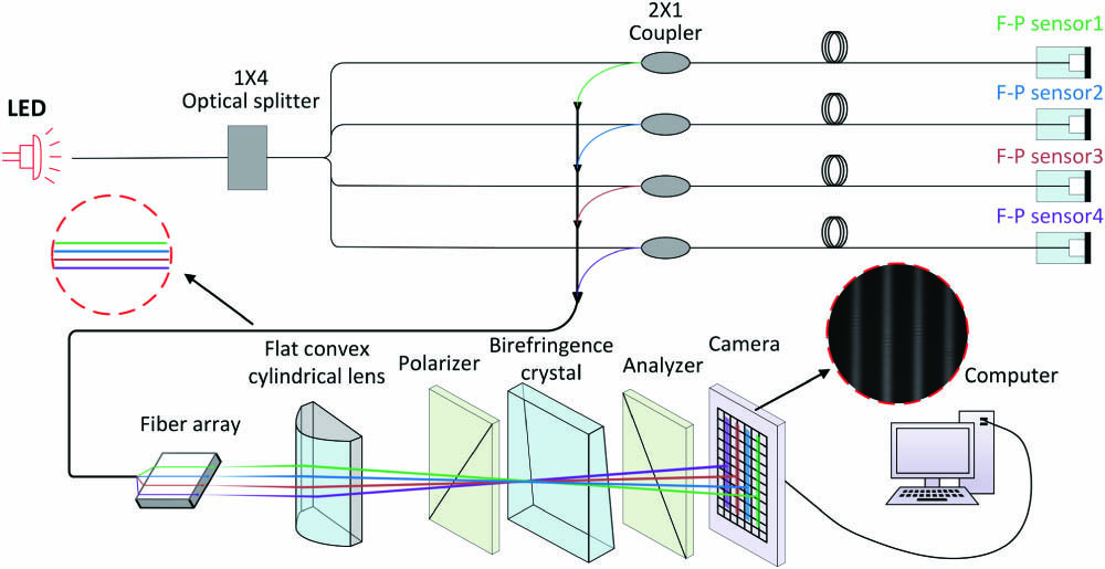
Figure 1 is the schematic diagram of the polarized multi-channel synchronous demodulation system. The sensing interferometer is composed of four F–P sensors; the light from an LED is divided into four equal parts through a 1 × 4 optical splitter and guided into each F–P sensor. The output optical signal from the four F–P sensors launches into the demodulating interferometer simultaneously. The demodulating interferometer consists of a fiber array placed horizontally, a plano-convex cylindrical lens whose refractive power meridian is parallel to the fiber array, a polarizer, a birefringence, and an analyzer. The polarization axes of the polarizer and analyzer have a 45° angle with the optical axis of the birefringence crystal. When the optical path difference (OPD) caused by the birefringence crystal is equal to that caused by the sensing interferometer, i.e., at the position of the matching-OPD, the low-coherence interference fringe (LCIF) appears. A matrix CCD is then used to catch the LCIF.

Figure 1.Schematic diagram of the polarized multi-channel synchronous demodulation system.
In order to realize the synchronous demodulation of multiple sensors, the proposed system has a few improvements compared to the traditional PLCI system. The light guided into each F–P sensor is divided into four equal parts from the same LED to eliminate the deviation caused by different light sources. Then a fiber array is used to make sure that the output optical signal from the sensing interferometer will launch into the demodulating interferometer simultaneously. Following that is a plano-convex cylindrical lens that is vertically placed to compress the divergent light emitted from the fiber into the cylindrical beams. A matrix CCD is placed to catch the signal beams collectively and simultaneously with the interference signals of each channel separating from each other, which means the proposed system can realize synchronous demodulation of multiple sensors without special requirements for sensors and light sources.
Assuming that the spectrum of LED conforms to the Gaussian shape, it can be expressed as where is the wavenumber, , is the full width at half-maximum of the power spectrum in the wavelength domain, is the central wavelength of the LED, and is the central wavenumber. The interference fringe intensity of channel can be described as where is the thickness of the birefringence crystal, is the sensor cavity length corresponding to channel , and is the refractive index difference between ordinary light (o light) and extraordinary light (e light).
Once the parameters of each component in the system have been determined, we can calculate the maximum number of channels that the system can synchronously demodulate in the ideal case, which can be translated into the imaging width of the light emitted by the fiber array on the CCD. In the horizontal direction, it is obvious that the birefringence crystal can be regarded as a parallel plate, which has no effect on the size of the image in the optical system, and thus it can be omitted when we calculate the imaging size of the optical system. The schematic diagram of horizontal section optical path analysis is shown in Fig. 2.
Figure 2.Schematic diagram of the horizontal section optical path analysis.
In Fig. 2, the plano-convex cylindrical lens is simplified to an object principal plane and an image principal plane. The optical axis is parallel to the channels in the fiber array and coincides with the upper edge of channel 1(). A part of the light from channel 1() and channel () is marked as the green lines and purple lines to reveal the imaging range of all channels in the fiber array on the matrix CCD. Then the points and are placed to represent the lower and upper boundaries of the imaging range. We consider the portion between the upper edge of and the lower edge of as the object of this optical system, and thus the image produced by the object should be presented between the points and . When the number of channels reaches the maximum, i.e., the image width of the system is equal to the horizontal width of the matrix CCD, the image width of each channel is equal to the width of each pixel of the matrix CCD. Assuming the matrix CCD contains pixels in the horizontal direction and the width of each pixel in the horizontal direction is , then the maximum number of channels that can be demodulated synchronously is identified by where the function returns an integer that is the nearest to the parameter in the parentheses in the direction of negative infinity, is the fiber core diameter of each channel in the fiber array, and denotes the distance between the fiber cores of two adjacent channels. Since the image width of the system is determined, the object distance of the optical system can be obtained according to Newton’s law, and it can be expressed as where identifies the effective focal length of the cylindrical lens.
For the experimental system we used in Fig. 1, the number of pixels in the horizontal dimension of the matrix CCD is 3296, the fiber core diameter of each channel in the fiber array is 62.5 μm, and the distance between the fiber cores of two adjacent channels is 83.5 μm, that is to say, , , and , which can be substituted into Eq. (3) to obtain the theoretical maximum number of sensing channels that the experimental system can demodulate simultaneously, and the result is calculated as 1410.
However, in the actual experiment, as the cylindrical lens that aggregates light in this system is a single spherical lens, it will produce a certain aberration in the convergence direction during the imaging process, i.e., the imaging width of each channel on the CCD in the actual experiment will be wider than the theoretical calculation, since the aberration can be reduced by adding the aberration system after the cylindrical lens, with the imaging width of the actual channels being close to the theoretical imaging width. The research on the single spherical aberration system is comprehensive[15,16], which is not repeated here.
The experiment was carried out using the abovementioned system to verify the feasibility of the proposed method, as shown in Fig. 1. Here, we put the F–P sensors in an air pressure chamber in which the pressure can be precisely tuned by a controller with a control precision of 0.02 kPa to generate a stable change of the F–P cavity length. The F–P pressure sensor has a silicon diaphragm, which turns the change of external air pressure into the change of F–P cavity length. Four 3 dB couplers and a matrix CCD (Thorlabs, 8051M) that has pixels are used in the experiment; the size of pixels is .
Figure 3 shows the interferogram detected by the matrix CCD when the air pressure is 101 kPa, where the imaging beams and the LCIF of each channel can be clearly observed. In addition, as the LCIF appears at the position of the matching-OPD, the position of the LCIF is closely related to the length of the sensor’s cavity, resulting in the LCIF of the four channels corresponding to four F–P sensors with different cavity lengths appearing at different positions in the imaging beams.
Figure 3.Interferograms of four channels detected by the matrix CCD when the air pressure is 101 kPa.
Figure 4 shows the signal of each channel extracted by the above method when the air pressure is 101 kPa, where the interference signal could be obviously observed. The air pressure is increasing from 100 kPa to 200 kPa at intervals of 2.5 kPa in the demodulation experiment, where we can use the method mentioned above to get the absolute phase corresponding to the selected monochrome frequency. Then the linear fitting can be utilized to establish a mapping relationship between the absolute phase of the selected monochromatic frequency and the corresponding air pressure. On the basis of this relationship, we can demodulate the pressure value measured by the calibrated sensor according to the absolute phase of the selected monochrome frequency.
Figure 4.Signals of channels 1–4 when the air pressure is 101 kPa.
The simultaneous demodulation of four channels is shown in Fig. 5, where we can see a good linear relationship between the absolute phase of the selected monochromatic frequency and the corresponding air pressure with the linear correlation coefficients of 0.99999, 0.99996, 0.99998, and 0.99998, respectively. Since the F–P sensors of channels 2, 3, and 4 have the same thickness of silicon diaphragm, which is different from that of channel 1, the fitting linear slopes of channels 2, 3, and 4 are almost identical, with a significant difference from that of channel 1. Furthermore, the sensors of the four channels vary in cavity length, leading to a different fitting line intercept for each sensor. These illustrate the wide applicability of the proposed system to the sensors to some extent.
Figure 5.Relationship between the absolute phase and the corresponding air pressure of the four channels.
As we obtained the measured pressures by the relation which was established in calibration process, the pressure measurement errors and the standard deviations of different channels are shown in Fig. 6.
Figure 6.Pressure errors and standard deviations of channels 1–4 within the air pressure measuring range.
As is shown in Fig. 6, the proposed system could maintain a tolerance of no more than 0.2 kPa for all sensing channels, which was similar to that of the traditional synchronous demodulation system based on a linear array CCD[9].
In conclusion, a multi-channel synchronous demodulation system is proposed to enable F–P sensors of different channels to be demodulated at the same time. A matrix CCD is placed to catch the interference signal from each channel simultaneously, which is extracted separately from each other and demodulated synchronously by the absolute phase recovery algorithm to get the final demodulation result. We carried out pressure experiments to verify the effectiveness of the proposed system. The results showed that the F–P sensors can be demodulated synchronously with the demodulation error similar to that of the traditional PLCI based on a linear CCD to the extent acceptable. In contrast, with the traditional multiplexing schemes based on a linear array CCD having limits on light sources or sensors, the proposed system shows no special requirements for light sources or sensors, which allows any sensor and light source that can be demodulated by a PLCI to be employed, which broadens the application range of synchronous demodulation system greatly.
References
[1] S. A. Al-Chalabi, B. Culshaw, D. E. N. Davies(1983).
[2] A. F. Fercher, C. K. Hitzenberger, M. Sticker, R. Zawadzki, B. Karamata, T. Lasser. Opt. Commun., 204, 67(2002).
[3] G. H. T. Dresel, H. Venzke. Appl. Opt., 31, 919(1992).
[4] Y. Wang, L. Feng, L. Zhu, H. Zhou, Z. Ma. Chin. Opt. Lett., 16, 031701(2018).
[5] B. Xu, Y. Liu, D. Wang, J. Li. J. Lightwave Technol., 34, 4920(2016).
[6] K. Li, M. Jiang, Z. Zhao, Z. Wang. Opt. Commun., 389, 234(2017).
[7] C. Gouveia, M. Zibaii, H. Latifi, M. J. B. Marques, J. M. Baptista, P. A. S. Jorge. Sens. Actuator B, 188, 1212(2013).
[8] Y. Yuan, B. Wu, J. Yang, L. Yuan. Opt. Lett., 35, 3357(2010).
[9] J. Yin, T. Liu, J. Jiang, K. Liu, S. Wang, F. Wu, Z. Ding. Opt. Lett., 38, 3751(2013).
[10] J. L. Santos, D. A. Jackson, 184(1992).
[11] J. Jiang, T. Liu, Y. Zhang, L. Liu, Y. Zha, F. Zhang, Y. Wang, P. Long. Opt. Lett., 30, 604(2005).
[12] Y. Rao, C. Zhou, T. Zhu. IEEE Photonics Technol. Lett, 17, 1259(2005).
[13] J. Jiang, S. Wang, T. Liu, K. Liu, J. Yin, X. Meng, Y. Zhang, S. Wang, Z. Qin, F. Wu, D. Li. Opt. Express., 20, 18117(2012).
[14] X. Gui, M. A. Galle, L. Qian, W. Liang, C. Zhou, Y. Ou, D. Fan. Chin. Opt. Lett., 16, 010606(2018).
[15] J. C. Hsu, C. C. Lee. Jpn. J. Appl. Phys., 47, 154(2008).
[16] F. Wang, Y. Cai, B. J. Hoenders. J. Opt. Soc. Am. A, 31, 48(2014).