Molecular alignment and orientation by laser fields has attracted significant attention in recent years, mostly due to new capabilities to manipulate the molecular spatial arrangement. Molecules can now be efficiently prepared for ionization, structural imaging, orbital tomography, and more, enabling, for example, shooting of dynamic molecular movies. Furthermore, molecular alignment and orientation processes give rise to fundamental quantum and classical phenomena like quantum revivals, Anderson localization, and rotational echoes, just to mention a few. We review recent progress on the visualization, coherent control, and applications of the rich dynamics of molecular rotational wave packets driven by laser pulses of various intensities, durations, and polarizations. In particular, we focus on the molecular unidirectional rotation and its visualization, the orientation of chiral molecules, and the three-dimensional orientation of asymmetric-top molecules. Rotational echoes are discussed as an example of nontrivial dynamics and detection of prepared molecular states.
Intense ultrashort laser pulses with electric field strength comparable to the intramolecular Coulomb field are routinely used to control the various molecular degrees of freedom, covering a wide range from bound valence electrons to the rotational and vibrational motion of the nuclei. The strong laser fields can polarize the valence electrons or even completely free them from the molecule. Using nonresonant laser pulses, molecular axes can be aligned or oriented along specific directions in space. The control of molecular rotation by laser pulses has been a very active field,1–5 where the focus has been on aligning/orienting otherwise isotropic molecular gases. Here alignment is defined as constraining a molecular axis along the polarization axis of the field, and orientation further requires breaking head-versus-tail symmetry, if such symmetry exists in the molecules. In many cases, alignment or orientation is a crucial prerequisite for further applications, including molecular orbitals tomography,6–10 imaging of molecular structure and dynamics with femto or attosecond laser pulses or ultrafast electron pulses,11–19 optical image storage,20 chemical reaction control,21,22 manipulation of nonlinear propagation of intense ultrashort laser pulses in molecular gas,23 and characterization of ultrashort laser pulses.24
Molecular ensembles excited by tailored laser fields are interesting in their own right from the fundamental point of view, and quite a few quantum and classical effects have been discovered or demonstrated in such molecular systems. Depending on the laser-pulse characteristics, laser-induced alignment can be classified as either adiabatic or impulsive.1,2,4,25–28 In the latter case, a coherent rotational wave packet is created, which can be further manipulated and probed by various methods. Such wave packets provide a unique opportunity for exploring fundamental quantum phenomena, i.e., quantum revivals,29–33 Anderson localization,34 and Bloch oscillations.35 More recently, a new classical phenomenon of molecular alignment echo36–38 was reported, where much like other echoes, following excitation by a pair of time-delayed short laser pulses, a series of impulsive responses (echoes) appear, with a period equal to the time delay between the two initial pulses.
Over the years, various approaches have been developed for the enhancement of field-free alignment,39,40 for generating and controlling complicated rotational wave packets of polyatomic molecules,41–43 and for orienting molecules by means of combinations of more than one laser field.44–52 Using sophisticated polarization-shaped laser fields, it is possible to orient the averaged angular momentum, thus preparing a unidirectionally rotating (UDR) molecular ensemble. The types of field combinations capable of initiating UDR include a pair of cross-polarized (typically at ) time-delayed pulses,53–55 chiral trains of short pulses,56,57 polarization-shaped pulses,58,59 and the optical centrifuge originally introduced almost 20 years ago,60–64 and improved more recently.63,64 So far, much of the work involved small linear molecules. When chiral molecules are involved, the effect of twisted polarization is more subtle, and in addition to UDR, the light induces partial orientation along the light propagation direction65–68 (see below).
Sign up for Advanced Photonics TOC. Get the latest issue of Advanced Photonics delivered right to you!Sign up now
In the last decade, molecules dissolved in superfluid helium (He) droplets are used as a versatile platform for studying many body physics. This new research field was pioneered by Stapelfeld’s group and included the topics of laser-induced alignment in the presence of dissipative environment,69,70 long-lasting field-free one-dimensional (1-D) and three-dimensional (3-D) alignment,71 achieving record degrees of alignment,72 extending the approach to molecular dimers,73 and structural determination of molecular complexes.74 For describing the molecular “impurity” embedded into the He droplet, Schmidt and Lemeshko75 introduced the concept of “angulon”—a quantum rotor dressed by a quantum field. Among others, the angulon theory proved to be successful and efficient for describing the experimental results of laser-induced molecular alignment.70,76 For a recent review of this vast field, we refer readers to Ref. 5.
The topic of molecular alignment and orientation has been reviewed several times and by different authors: Stapelfeldt and Seideman1 covered the historical development of molecular alignment; Ohshima and Hasegawa2 focused on state-resolved probing of impulsively excited alignment and UDR; and Fleischer et al.3 reviewed selective rotational excitation by a pair of pulses, including isotope identification and unidirectional control, together with surface-scattering rotational dynamics. A more recent review by Koch et al.5 provides a more general perspective of quantum control. To minimize overlap with these previous reviews, here we focus on the most recent progress on laser-induced molecular alignment and orientation, including optically induced molecular UDR, all-optical field-free partial and 3-D orientation of asymmetric-top molecules, and rotational alignment echoes.
This article is organized as follows. We begin with a discussion of the various methods used to generate UDR in linear molecules, including a pair of time-delayed cross-polarized pulses, and more sophisticated implementations of pulses with twisted polarization. We continue with the detection of the spatiotemporal evolution of the molecules either achieved by traditional optical birefringence methods or by Coulomb explosion. Next, we discuss asymmetric-top molecules, which are of special interest as this class of molecules includes the chiral molecules. Here we focus on the successful efforts to achieve orientation under field-free conditions. Two novel and principally different mechanisms for inducing orientation in asymmetric-top molecules are discussed. The first involves single-color laser fields with twisted polarization and the interaction of which is second order in the electric field (polarizability interaction), whereas the second involves a combined two-color field, in which the polarizations of the fundamental wave (FW) and its second harmonic (SH) are orthogonal. In this case, the interaction is third order in electric field (hyperpolarizability interaction). The fourth part of the review is devoted to rotational alignment echoes following excitation by a pair of time-delayed ultrashort laser pulses. Periodic alignment events (echoes) appear at time delays equal to the interval between the two excitation pulses. Various types of rotational echoes are investigated both theoretically and experimentally and are used to probe the collisional dynamics of dense molecular gases. The review ends with some general observations on the future of this field.
2 Initiation and Visualization of Molecular Unidirectional Rotation
We begin with a brief description of the basic principles of laser-induced molecular alignment starting from the simple case of diatomic molecules. For most phenomena considered in this paper, molecules can be assumed to be rigid and therefore treated as rigid tops.77,78 We begin with the simplest case of a diatomic molecule. The rotational dynamics of such objects are characterized by the moment of inertia , where is the reduced mass of the molecule and is the interatomic distance (the “bond length”). In the case of linear molecules, the angular momentum and angular velocity vectors are proportional to each other, with the moment of inertia being the constant of proportionality, .77 In addition, for linear molecules the angular momentum is always perpendicular to the molecular axis. As a result, free rotation of a linear molecule in space fixed coordinate system is completely defined by specifying the conserved vector of angular momentum.
The interaction energy and the torque applied by off-resonance optical fields are given by respectively, where is the external field and is the dipole moment induced by the external field. The induced dipole is proportional to the external field, and in case of linear molecule and , where the constants of proportionality are the relevant polarizabilities. The symbols and denote the directions along and perpendicular to the molecular axis, respectively. Usually, means that diatomic molecules are easier to polarize along the molecular bond. In this paper, we consider optical laser pulses at central frequency , which is much higher than the typical rotational frequency of small molecules (where is Planck’s constant), therefore all the pulses are indeed far off-resonance and the above equation for interaction energy can be employed. For the case of a linear molecule excited by a linearly polarized pulse, the interaction energy is given by , where is the angle between the molecular axis and laser polarization direction, and is the amplitude of the external field. The magnitude of the torque exerted on the molecule is given by . When the optical pulse is short (on the order of 10th of femotoseconds) compared to the typical rotational period of small molecules at ambient conditions (on the order of picosecond), it impulsively “kicks” the molecules toward the line defined by the polarization of the field. Postpulse rotation of the molecules with the acquired angular velocities results in a squeezed angular distribution, which peaks along the polarization axis of the applied laser pulse. The angle dependence of the potential implies that the molecules are being aligned but not oriented, i.e., there is no head-versus-tail difference. In the absence of additional fields, the molecules continue to rotate after the transient alignment and, if were classical, would normally continue to rotate without reaching the same degree of alignment again. However, due to the discreteness of the rotational energy levels and their associated commensurate energies, rotational quantum revivals29–33 are observed, which are manifested as periodically occurring squeezed angular distributions following the initial pulse.
For the single-pulse excitation, as well as for multiple pulse excitation where all the pulses are polarized in the same direction, no preferred sense of rotation exists, due to the axial symmetry of the excitation. In order to “inject” angular momentum into the medium and to force molecules to rotate with a preferred sense, one has to break the axial symmetry. One way to achieve this is using a field with twisted polarization. The simplest example of such a field is a pair of delayed cross-polarized femtosecond laser pulses. The first pulse aligns the molecules along the polarization direction. The second pulse is applied at the moment of maximal alignment, and it is polarized at an angle () to the first one. The second pulse induces a UDR of the molecules. The ensemble averaged angular momentum is no longer zero and becomes oriented along the direction perpendicular to the plane of pulses’ twisting. As can be expected, the maximal angular momentum is achieved when the two pulses are polarized at with respect to each other.
2.1 Laser Fields with Twisted Polarization
The simplest laser field that is not right/left symmetric is a circularly polarized field. However, it is worth noticing that a simple circularly polarized light cannot be used to induce UDR, due to the many orders of magnitude difference of time scales of the rotation. Typical rotational period of molecules is on the picosecond timescale, whereas the period of the circular polarization for an optical pulse is of the order of femtosecond. There are several types of twisted-polarization laser fields that have been demonstrated to induce UDR, including the double-pulse kick scheme,53–55 the chiral train of ultrashort pulses,56,57 the polarization-shaped pulse,58,59 and the optical centrifuge.60–64 Although these are very different fields, they all orient the molecular averaged angular momentum vector. A short review of these fields follows.
2.1.1 Double pulse excitation
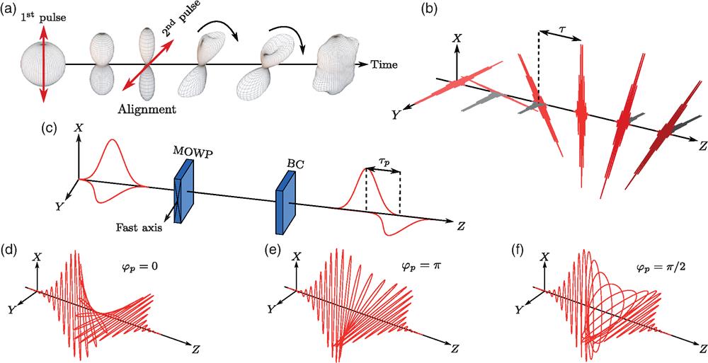
The simplest example of a laser field with twisted polarization is a pair of time-delayed cross-polarized femtosecond pulses. This excitation technique, sometimes referred to simply as a “double-pulse kick” [see Fig. 1(a), red arrows], had been suggested in Refs. 53 and 54, experimentally demonstrated in Refs. 54 and 80–82, investigated in detail, both from the quantum and classical perspectives, in Ref. 55, and generalized to chiral trains of multiple pulses56,57,79 [see Fig. 1(b)]. Figure 1(a) illustrates the evolution of the molecular angular distribution as a result of the double-kick excitation. After the first pulse, the most polarizable molecular axis (MPA) is “kicked” toward the direction defined by the laser polarization and after a short time the MPA becomes aligned along it. In the simple case of linear molecules, the MPA coincides with the symmetry axis. At the moment of maximal alignment, a second cross-polarized pulse (typically polarized at to the first pulse) is applied initiating an in-plane rotation of the aligned MPA. The plane is defined by the two polarization vectors and the molecular motion resembles the spinning of an aircraft propeller. The sense of rotation coincides with the sense of polarization twisting of the two laser pulses. This excitation results in orientation of the ensemble averaged angular momentum along the direction perpendicular to the plane defined by the twisting polarization vectors of the two laser pulses. The rotation frequency of molecular propellers is typically on the order of 1 THz. It is possible to increase the excitation efficiency by applying a series consisting of more than two pulses, continuously kicking the molecules and increasing the angular momentum, as schematically shown in Fig. 1(b). To reduce the energy loss during the pulse train excitation, a subtle design of the intensity of the pulses in the train is required.56,57,79 Recently, Misuze et al.83 demonstrated that by applying a properly timed third (control) pulse it is possible to accelerate/decelerate UDR molecules.
The idea behind the polarization-shaped pulse is to partially overlap two orthogonally polarized femtosecond laser pulses, such that the polarization of the resulting pulse rotates continuously in the region of overlap. This approach is different as compared to the previously introduced double-pulse scheme, in which the twisting is discrete in time. Polarization-shaped pulse was used by Kida et al.84,85 to broaden the spectrum of a femtosecond pulse through self-phase modulation in order to rotationally excite molecule through impulsive stimulated Raman scattering, whereas the sense of the induced rotation was not considered. Later, Karras et al.58 revisited the molecular UDR implementing a variant that allows a fine control over the polarization of the shaped pulse. Experimentally, in the latter case, the polarization shaping was accomplished by multiple order wave plates (MOWP) in conjunction with a Berek compensator (BC) [see Fig. 1(c)]. By introducing a single femtosecond pulse polarized at with respect to the fast (slow) axis of the MOWP, the pulse is split into two time-delayed subpulses with orthogonal polarization. The time delay is determined by the order of the MOWP. To precisely control the polarization in the temporally overlapped region, a BC is placed after the MOWP in order to finely adjust the phase between the two subpulses. Figures 1(d)–1(f) depict the polarization-shaped pulses with various relative phases. A polarization-shaped pulse enables molecular UDR since the rate of polarization twisting is made comparable to typical rotation period of molecules at ambient conditions. To maximize the efficiency of UDR excitation, the relative phase between the two orthogonal components should be precisely tuned to be 0 or .
2.1.3 Optical centrifuge
Karczmarek et al.60 proposed a laser field with continuously twisting polarization, termed an optical centrifuge. The optical centrifuge is a laser pulse, whose polarization vector undergoes an accelerated rotation around its propagation direction , as shown in Fig. 2(a). To generate an optical centrifuge pulse, the spectrum of broadband laser pulses is split in the center of its spectrum [horizontal dashed line in Figs. 2(b) and 2(c)] in two equal parts using a Fourier pulse shaper. The two subpulses are frequency chirped with a chirp rate (typical values are ) of equal magnitude and opposite sign [see Fig. 2(c)]. The chirped subpulses are then combined with a polarizing beam splitter and polarized with an opposite sense of circular polarization. Optical interference of these laser fields results in a pulse illustrated in Fig. 2(a). The polarization vector rotates in plane with an instantaneous angular frequency . The maximum rotation frequency is determined by the bandwidth of the input pulse.
The optical centrifuge was successfully implemented by Villeneuve et al.61 and was used to accelerate the rotation of the molecules up to 6 THz within 50 ps. The centrifugal forces were strong enough to break the molecular bond. The introduction of the optical centrifuge opened up a broad field of new investigations of rotating molecules. Dissociation and multiple collision processes were used as an indicator to the formation of “molecular superrotors.”61,62 Molecular superrotors were further studied, controlled, and characterized by Korobenko et al.63 who used the rotational Doppler effect as a measuring tool (see Sec. 2.2 and Fig. 3). The dynamics and the physical properties of these superrotors were investigated;86,87 their magneto-optical properties were studied.88 Ultrafast magnetization of a dense molecular gas was experimentally observed.89 Collisions in a dense gas of UDR molecules were numerically shown to induce macroscopic vortex gas flows.90 A two-dimensional (2-D) optical centrifuge was proposed as a tool to produce long-lived alignment.91 A comprehensive theoretical study of centrifugation of linear molecules was done in both classical and quantum mechanical frameworks.92,93 Numerical description of asymmetric-top superrotors was given by Omiste.94 Recently, enantioselective orientation of chiral molecules was demonstrated using the optical centrifuge.68 For a comprehensive review of experimental developments utilizing the optical centrifuge, the reader is referred to Ref. 64.
Figure 3.Experimentally observed RDS for deuterium molecules. (a)–(c) The spectra, shown as 2-D color-coded plots, were measured with a probe scan delay of 150 fs around the midway point between the pump pulses. (d)–(f) Normalized spectra measured at the probe delay time that produced the maximum signal [indicated by the horizontal gray lines in (a)–(c)]. Vertical black line marks the central wavelength of the unperturbed probe. (a), (d) A single pump pulse is applied, resulting in no UDR and no RDS. (b), (e) The molecules are set to rotate in the same sense as the CP probe, producing a red shift. (c), (f) The molecules are set to rotate in the opposite sense, producing a blue shift. This figure is reproduced with permission from Ref. 80.
The first experimental measurement of molecular UDR was realized by Kitano et al.54 using frequency-resolved spectroscopic method of resonantly enhanced multiphoton ionization (REMPI), where a circularly polarized nanosecond dye laser pulse was used to ionize the molecules. In case of UDR molecules, rotational states with quantum number (projection of total angular momentum on a laboratory axis) of opposite sign are unequally populated. States with positive/negative are preferentially ionized by left/right circularly polarized probe pulse, respectively. Comparison of the ionization yield obtained in these two cases, also termed as circular dichroism, allows to detect molecular UDR as well as to determine the sense of rotation. The REMPI scheme has been reviewed in the past.2 In this paper, we focus on detection schemes based on the rotational Doppler shift (RDS), Raman shift, and Coulomb explosion, which allow us to resolve the temporal evolution of UDR molecules.
2.2.1 Rotational Doppler effect and Raman shift
Molecular “propellers” (or “superrotors”) rotate at much higher frequencies than any other mechanical rotors, providing an unprecedented opportunity to investigate the rotational Doppler effect at the molecular level. Doppler effect is a well-known phenomenon, manifesting in a frequency shift of a wave due to a relative motion of the source and receiver. Consider the linear Doppler effect for light emitted by a moving object or reflected from a moving object, the observer measures a frequency shift or in the first and second cases, respectively. Here is the light frequency, is the relative velocity, and is the speed of light. The frequency shift doubles in the latter case since the direction of the velocity vector is inverted after reflection. This is similar to a ball bouncing off a moving heavy wall. Analogous to the linear Doppler effect, when a circularly polarized light reflects off a rotating object, its frequency is Doppler shifted. Rotational frequencies of mechanical rotors are small when compared to the light frequency, making the measurement of the frequency shift quite challenging.95–99 With the fast-rotating molecules, Korech et al.80 successfully measured the rotational Doppler effect from a sample of UDR molecules by measuring the frequency shift of circularly polarized light scattering of the rotating molecules. Figures 3(a)–3(c) show the spectra in cases when the molecules are excited by a single linearly polarized pulse (no UDR) and by a pair of time-delayed cross-polarized pulses inducing UDR coinciding or opposing to polarization rotation of the probe pulse. Depending on the sense of molecular UDR, red or blue probe frequency shift is measured. The rotational Doppler effect is essentially equivalent to the Raman shift, both of which result from the nonresonant scattering of the incident photons, and the effect may be described in both languages. Korobenko et al.63 observed the continuous Raman frequency shift in linear molecules excited by an optical centrifuge. Figure 4 shows the measured Raman shifts as a function of time.
2.2.2 Wave packet visualization by Coulomb explosion
Although spectroscopic measurements can provide information about the rotational direction and frequency of molecular rotors, spatiotemporal evolution of the rotational wave packet remains hidden. The Coulomb explosion imaging (CEI) technique addresses this problem.
An intense () ultrafast laser pulse is used to break/explode the target molecules by rapidly removing many electrons, resulting in the Coulomb repulsive fragmentation of the residual highly charged molecular ions along the bond axes (axial recoil approximation). Pump–probe scheme providing femtosecond temporal resolution in combination with particle detection techniques of solid angle resolution ensures the success of CEI. The fidelity of CEI technique is commonly based on the following three assumptions: (I) the electronic recoil is ignored due to the huge nuclei/electron mass ratio. (II) The molecules are assumed to be stationary during the ultrafast Coulomb explosion process. (III) The molecules undergo negligible structural deformation during the strong-field multiple ionization process. The last two assumptions rely on the short duration of CEI pulse, typically on the femtosecond time scale, much shorter than the rotational period, which is typically on the picosecond time scale. The cold target recoil ion momentum spectroscopy (COLTRIMS)100,101 and velocity map imaging (VMI)102 are generally two techniques used to detect the ejected ionic fragments for the CEI measurements. Examples of state of the art experiment utilizing the VMI techniques can be found in Refs. 103 and 104 (and the references therein).
Figure 5 schematically illustrates the typical CEI setup. A circularly polarized CEI probe pulse is focused on the molecular jet inside the vacuum chamber of COLTRIMS or VMI, to detect molecules at variable delay after a twisted polarization pulse(s) giving rise to UDR excitation. The fragment ions are focused by an electrostatic lens and detected by the ion detector. The orientation of molecular axes at the time of the Coulomb explosion can be deduced from the recorded positions of fragments’ impact. The essential advantage of the COLTRIMS over VMI is the capability of coincident measurement, which enables the identification of ion-pairs ejected from the same molecule, based on conservation of momentum of the exploding system.
The first experimental visualization of double-pulse-kicked UDR was implemented by Lin et al.81 using COLTRIMS and by Mizuse et al.82 using VMI. The experimental results are shown in Figs. 6(a) and 6(b), respectively, where the impulsively kicked “molecular propeller” exhibits complex quantum beating behaviors. In Fig. 6(a), the alignment pulse is applied at , after which the molecular rotors are aligned along the polarization direction (angles 0 and ). After the excitation, the rotational wave packet freely evolves. Aligned and antialigned states periodically reappear as a result of quantum beating of the rotational states forming the coherently generated rotational wavepacket. The second kick pulse, polarized at to the first one, is applied at the moment of maximal alignment during the first full revival event, at . All molecules experience the same torque and begin rotating unidirectionally. This rotation is manifested in tilted parallel stripes structure seen in the angular distribution after the application of the second kick pulse [see Fig. 6(a)]. Comparison of the angular distribution at half revival time () and after revival (after the second kick, ), provides a qualitative picture of the UDR dynamics induced by a pair of cross-polarized pulses. Driven by only a single alignment pulse, molecules rotate both clockwise and anticlockwise [see the crossed structure in Fig. 6(a), ]. In contrast, after applying the second kick pulse at , the angular distribution has a parallel stripes structure (), a clear sign of molecular UDR.
In contrast to the dispersive rotational wavepacket of impulsively kicked “molecular propellers,” using the optical centrifuge, Korobenko et al.105 experimentally prepared and observed the nondispersing quantum “cogwheel state” of molecules. The deuterium molecules are lighter with a larger energy spacing between the rotational levels allowing to tune the terminal frequency of the centrifuge such that just the and states are coupled (for ortho-deuterium). After releasing the molecules from the optical centrifuge, an intense, circularly polarized probe pulse was applied to follow the rotational wave packet evolution. As shown in Fig. 6(c), the resulting field-free angular distribution evolves without spreading, preserving its shape at all times.
3 All-Optical Field-Free Orientation of Complex Molecules
Over the years, several optical approaches have been developed to orient simple and complex molecules in space. Early proposals included combinations of nonresonant laser fields with weak electrostatic fields.106–110 With the advent of terahertz (THz) technology, THz pulses were shown to be efficient in inducing orientation.39,45,111–115 In some works, THz pulses were combined with optical ones.116–119 Nonresonant phase-locked two-color laser pulses were proved to be useful for orienting linear molecules, and the orientation mechanism was shown to depend on the nonlinear interaction with molecular hyperpolarizability.44–52
In this paper, we would like to focus on the orientation of complex molecules having different geometries and belonging to various symmetry point groups.120 The rotational dynamics of rigid bodies can be classified based on the eigenvalues of the moment of inertia tensor. The moment of inertia tensor describes the mass distribution inside the rigid body about an arbitrary point. For practical purposes, the moment of inertia tensor is usually calculated with respect to the center of mass and is represented in a molecule-fixed frame of reference. The moment of inertia relates the angular momentum and the angular velocity vectors, . By definition,77,121 is a symmetric matrix and therefore diagonalizable. The three eigenvectors of the moment of inertia tensor are called the principal axes of inertia. The frame defined by the principal axes will be denoted by . Classification of rigid bodies is based on the relation between the three eigenvalues of the moment of inertia matrix—these are simply called “moments of inertia” and are usually denoted by , , . There are four distinct types of rigid bodies.
The interaction between a complex molecule and a nonresonant optical field depends on the polarizability tensor and is given by , where are the components of the polarizability tensor, and are the components of the external electric field. As noted, the nonresonant polarizability tensor, expressed with respect to the center of mass, is symmetric; its three eigenvectors will be referred to as the principal axes of polarizability, and the eigenvalues are called polarizabilities. The frame defined by the principal axes of polarizability will be denoted by .
The relation between polarizabilities depends on molecular symmetry. For example, in case of linear molecules and symmetric top molecules, two of the polarizabilities are equal. In case of asymmetric top molecules, all three polarizabilities are different. Description of the laser driven dynamics requires expressing the polarizability tensor in the frame defined by the three principal axes of inertia. Two cases can be distinguished—the first one is when the polarizability is diagonal, meaning that the frame of inertia and polarizability principal axes coincide. This is true for molecules having some symmetries, for example, molecule, belonging to symmetry point group. The second case is when the polarizability matrix is nondiagonal, meaning that the frame of principal moment of inertia and polarizability tensors do not coincide. This is true for chiral molecules, for example, propylene oxide molecule (in short PPO) as illustrated in Fig. 7(b).
In cases when the exciting laser field is a superposition of two pulses at different central frequencies (i.e., FW and its SH) and it is sufficiently intense, one needs to consider the interaction to a higher order Here are the components of the hyperpolarizability tensor. The symmetry properties of the polarizability tensor can be generalized to the hyperpolarizability tensor as well. In case of off-resonant external fields, the tensor is symmetric in all indices.123 The number of unique elements of the hyperpolarizability tensor, as expressed in the frame of inertia principal axes, depends on the molecular symmetry. For example, the molecule has three elements, whereas in the case of chiral molecules there are ten unique elements.
3.1 Partial Transient and Persistent Orientation of Chiral Molecules
Chiral molecules cannot be superimposed with their reflection in a flat mirror.120,124 Chiral molecule and its reflected counterpart are called enantiomers. Chiral resolution (i.e., differentiation of enantiomers in a mixture containing both of them) is important in drug synthesis, as different enantiomers may have opposite biological activity.125 Nowadays, several research directions are explored, including measurements of enantiomeric excess, handedness of a given compound and developing techniques for enantioselective manipulation.126–137 Traditional chiral resolution methods include crystallization, chromatography, and using enantioselective enzymes. Recently, a number of new techniques have been developed for investigating chiral molecules in the gas phase. These include photoelectron circular dichroism using intense laser pulses or synchrotron radiation,136,138,139 CEI,133,135,140–142 microwave three-wave mixing,134,137,143,144 and orienting chiral molecules using a pair of cross-polarized laser pulses. The last approach was theoretically suggested in Ref. 65, based on quantum mechanical arguments and it relies on exciting UDR of molecules with the help of a double pulse. It was later shown66,67 that the enantioselective control mechanism is classical in nature and it was generalized to laser fields with twisted polarization (see Sec. 2.1). In the following two sections, we briefly describe the classical mechanism behind laser-induced orientation of chiral molecules and describe the counterintuitive long-term behavior of the excited chiral molecules.
3.1.1 Transient orientation
When applied to chiral molecules, the electric field of the twisted polarization pulse performs several functions: it induces alignment of the MPA as described in Sec. 2. The aligned molecular axis tends to follow the rotation of the polarization vector, but due to the inertia it lags behind. As was shown in Ref. 66, in the case of chiral molecules, the skewed twisting laser field induces a torque about the aligned molecular axis, which tends to orient the molecules in a direction perpendicular to the plane of twisting by rotating them about this axis. The orienting torque depends on the existence of off-diagonal elements of the polarizability tensor (as expressed in the frame of inertia principal axes). Physical properties of chiral molecules, such as permanent dipole moment and polarizability tensor, inherit the symmetry relation of the two enantiomers. Thus the components of the molecular dipole and the off-diagonal elements of the polarizability tensor that are connected by the reflection operation have opposite signs for the two different enantiomers. As a result, the above mechanical torque along the most polarizable axis has opposite signs for different enantiomers as well,66 leading to counterrotation of the molecules, which may be detected by observing, for example, their permanent dipole moments, which is rigidly attached to the molecule. When free induction decay is measured, the resulting emission from the gas bears information on the chiral composition of the mixture.65–67 The observable is not restricted to the molecular dipole and in fact it can be any vector. The classical nature of the above orientation mechanism ensures generality and operational robustness of the related prospective techniques for detecting and separating enantiomers of chiral molecules.
Recently, the enantioselective orientation described above was experimentally demonstrated68 using the optical centrifuge pulse (see Sec. 2.1). The two enantiomers of PPO molecule were spun in an optical centrifuge and it was shown that the centrifuge orients one of the PPO’s principal molecular axes either along or against the direction of light propagation. To detect the chirality-dependent rotation-induced orientation of PPO enantiomers, the technique of CEI was employed, whereby the velocities of the scattered fragments provide information on the spatial orientation of the molecule at the moment of explosion. A typical VMI setup102 was used, in which the molecular jet is intercepted by the probe beam (polarized along ) between the plates of a time-of-flight spectrometer [Fig. 7(a)]. The projection of their velocities on the plane is mapped on the plane of the detector. Mass selectivity is provided by gating the multichannel plate (MCP) at the time of arrival of the fragments of interest. The trajectories of the atoms that have been measured (carbon and oxygen atoms) are denoted by thin black and red lines in Fig. 7(b).
Two observables were considered: the 2-D alignment, of PPO’s principal axis [which is close to the MPA , see Fig. 7(b)] in the plane of rotation and the orientation, of the two “perpendicular to ” axes along the propagation direction of the beam. The former would confirm the controlled rotation of the molecules in the centrifuge, whereas the latter would confirm the orientation by a laser field with twisted polarization. Here is the angle between the projection of the fragment’s velocity and the laboratory axis [see inset in Fig. 7(a)], and implies averaging over the molecular ensemble. The value of above (below) 0.5 corresponds to the planar alignment (antialignment) of vectors with respect to axis. Similarly, positive (negative) values of reflect the orientation of along (against) the laboratory axis. Figures 7(c) and 7(d) show the average alignment and orientation values of the oxygen ion velocities for three delay times, corresponding to the Coulomb explosion prior to the arrival of the centrifuge (), during the centrifuge (10 ps) and after the end of the centrifuge excitation (30 ps). Both the alignment and the orientation of the carbon ion trajectories deviate from their isotropic values once the molecules are exposed to the centrifuge field. The observed antialignment [Fig. 7(c)] confirms the rotational excitation of PPO by the centrifuge: as the molecules are spun by the laser field with their most polarizable axis pulled toward the plane of rotation. Simultaneously, the less polarizable and axes, associated with the oxygen and the middle carbon atoms, respectively, tend to stick out perpendicular to that plane resulting in the observed orientation of oxygen and carbon velocities.
3.1.2 Persistent orientation
A fundamentally new aspect of field free orientation initiated by fields with twisted polarization was discovered66,122,145—the orientation does not return to zero shortly after the end of the excitation but persists over time exceeding the time scale of the excitation pulses by several orders of magnitude. In all the previously known approaches to impulsive orientation of nonchiral molecules, including techniques using single-cycle THz pulses,39,45,111–114,119 alone or in combination with optical pulses,116–118 or two-color laser fields,44–51,146 the orientation is short-lived and disappears rapidly after the end of the excitation pulses. Transient revival spikes may appear at longer times, however, they ride on a zero baseline and their time average is exactly zero. Currently, chiral molecules excited by laser fields with twisted polarization provide the first example of long-lasting permanent molecular orientation induced by a pulsed optical field.
The persistent orientation relies on the specific features of the asymmetric-top kinematics and on the molecular chirality. Figure 7(b) shows one of the enantiomers of PPO [right handed, (R)-PPO] with the mismatching and frames. At the classical level, the trajectories followed by the angular momentum vector in the frame are defined by energy and three components of angular momentum (in the laboratory frame). In frame, the angular momentum vector tip moves along closed trajectories defined by lines of intersection between an ellipsoid (with semiaxes , , and ) and a sphere (with radius ): Binet construction121 [see Fig. 7(e)] shows the allowed trajectories. Trajectories enclosing the poles of and axes are denoted by (), where refers to the positive/negative side of the axis. On these trajectories, the sign of is conserved and it matches the sign of the trajectory label (). This means that in the laboratory frame during free rotation of individual asymmetric-top molecules, their and axes on average point either along or against the conserved vector of angular momentum. Note that this is not true for the unstable rotation about axis.
It is possible to optically excite initially isotropic ensemble of chiral molecules in such a way that the ensemble-averaged quantities or (here is the laboratory axis) keep their sign unchanged. In other words, at the classical level of analysis, it is possible to permanently orient the molecular ensemble along the laboratory axis. This can be achieved by a combination of two processes: first, by orienting the averaged angular momentum vector along and, second, by breaking the versus symmetry.
Fields with twisted polarization in general, and the field of an optical centrifuge in particular, when acting on an ensemble of chiral molecules fulfill both requirements. An optical centrifuge orients the averaged angular momentum vector perpendicular to the plane of twisting (along the propagation direction of the laser beam, defined as laboratory axis). In the case of chiral molecules, there is an additional orienting torque that partially orients the molecules perpendicular to the plane of twisting that is along .66,67 This torque depends on the off-diagonal elements of the polarizability tensor as expressed in the frame, or in other words, on the mismatch between and frames. In addition, it can be shown that such a torque also breaks the versus symmetry, allowing the long-term orientation.145
Recently, persistent enantioselective orientation of chiral molecules was experimentally observed.122 Experimental observation time window was almost two orders of magnitude longer than the exciting pulse, confirming the longevity of the predicted orientation effect. Figure 7(f) shows the experimentally measured for the velocity distributions of fragments. The enantioselective effect of the centrifuge is reflected in the opposite sign of the 2-D orientation factor for the two enantiomers. The orientation factor reaches the values of the order of during the interaction with the centrifuge field (first 20 ps), being positive for left- and negative for right-handed molecules. When the interaction is over, the degree of orientation becomes smaller, but maintains a nonzero value for at least 700 ps (a maximum accessible delay time in the current experimental setup). As seen, the orientation signals of ions are opposite to each other for both enantiomers, as expected based on the qualitative arguments and the theoretical simulations.122
3.2 Three-Dimensional Orientation of Asymmetric-Top Molecules
Three-dimensional control of the rotational dynamics of complex molecules poses a significant challenge in the context of alignment/orientation of molecules. In the past, combination of DC field and long sharply truncated optical pulse was proposed for orientation of asymmetric-top molecules under laser-field-free conditions147,148 and more recently, pulsed laser fields with twisted polarization were shown to be effective for partial enantio-selective orientation of chiral molecules65–67 (see Sec. 3.1). Nonresonant phase-locked two-color laser pulses with parallel polarization were used for inducing orientation of linear molecules via nonlinear interaction with the diagonal elements of the molecular hyperpolarizability.44–51,149 Takemoto and Yamanouchi47 proposed an adiabatic scheme for 3-D orientation of chiral molecules by two-color fields. Chen et al.150 suggested to superimpose counter or co-rotating circularly polarized FW and SH laser fields to simultaneously orient linear molecules in multiple directions, which was more recently extended by Nakabayashi et al.151 to the case of symmetric-top molecules.
Here we review the first experimental demonstration of all-optical field-free orientation of asymmetric-top molecules using phase-locked orthogonal two-color (OTC) laser fields,146 consisting of FW and its temporally overlapped SH. The FW aligns the MPA of the molecule along the polarization direction, whereas the two fields together orient the molecules via the off-diagonal components of the molecular hyperpolarizability tensor. This interaction breaks the azimuthal symmetry and orients the second most polarizable axis (SMPA) after the end of the OTC pulse, resulting in field-free molecular orientation. The same principle applies to other nonlinear molecules similar to but with different arrangements of the polarization axes and intensity ratios, for example, iodobenzene [see Figs. 8(a) and 8(b)]. The orientation mechanism is briefly discussed using a simplified 1-D model, and the orientation is shown to depend on the relative intensity of the FW and SH field components. Most recently, the OTC pulses were applied to linear molecules in order to achieve an enhanced orientation effect.153
For the molecule, the axis is the major molecular axis with the largest polarizability, and the axis, bisecting the bond angle between the oxygen atoms, is the minor axis with the second largest polarizability [see Fig. 9(a)]. The molecular permanent dipole moment is directed against the axis (not shown). In these experiments, the laser pulses propagate along the axis. The FW is a polarized femtosecond laser pulse with wavelength of 790 nm and SH is a polarized pulse at 395 nm. The SH field temporally and spatially overlaps the FW and is phase locked to it. The OTC pulse is focused on a supersonic beam of molecules propagating along the axis. At a variable time delay after the application of the two-color pulse, an intense circularly polarized probe pulse is employed to explode the molecules and to image their 3-D spatial orientation via coincident CEI technique, as described in Sec. 2.2.
Figure 9.1-D model describing the OTC pulse-induced orientation. (a) molecule, the atoms are color coded: sulfur, yellow and oxygen, red. The major axis is perfectly aligned along the laboratory axis. The minor axis lies in the plane at an angle relative to the axis. (b) Potential energy as a function of for , [see Eqs. (3) and (4)]. This figure is from Ref. 146, CC BY 4.0.
The layout for constructing a collinearly propagating two-color field by nonlinear optical-mixing technique is schematically shown in Fig. 8(c). An FW laser pulse, typically 790 nm from a Ti:Sapphire laser, is down-collimated into a -barium borate (-BBO) crystal to generate a SH pulse at 395 nm. To compensate for different group delays at the two frequencies due to refractive index difference of the optical components, -barium borate (-BBO) crystals were introduced after the -BBO crystal.
A reflection mirror and a pair of wedges was used to adjust the relative intensity and phase between the two colors, respectively, enabling orientation of different molecules as well as control of the orientation direction. Figures 8(a) and 8(b) show the trajectories of the polarization vector tip of the OTC pulse.
3.2.2 One-dimensional model of molecular orientation
To illustrate the two-color orientation mechanism, we start with a classical ensemble of cold molecules whose major axis is perfectly aligned along the laboratory axis with a uniform random angular distribution of the molecular minor axis in the plane. The angle of rotation around the alignment axis is denoted by , see Fig. 9(a). At time , a short phase-locked OTC pulse is applied to the ensemble. The electric field of the OTC pulse is given by where are the unit vectors along the corresponding laboratory axes, are the field envelopes, is the carrier frequency of the FW field, and is the relative phase between the FW and SH fields. Using Eq. (1), we obtain where , , and () are the amplitudes of the laser fields. For molecules having symmetry, the hyperpolarizability tensor has three independent elements , , and .123,154 After averaging over the fast optical oscillations only terms proportional to contribute. The term arises from the field interaction with the molecular polarizability, whereas the term results from the hyperpolarizability interaction. Figure 9(b) shows for various values. As seen, the potential is a tilted double well with the tilt controlled by the relative phase . A kick by such a potential leads to the focusing of the angular distribution at shortly after the kick.39 If , the symmetry of the potential function is broken and the minima are no longer equivalent, manifested in the asymmetric shape of the angular distribution.
In general, interaction of the OTC pulse with the polarizability [the first term of the interaction potential, Eq. (1)] leads to the 3-D alignment. The hyperpolarizability interaction [the second term of the interaction potential, Eq. (1)] breaks the symmetry along the direction of SH. The qualitative reason behind this is the following: the FW induces (via off-diagonal hyperpolarizability elements) a dipole along the SH direction, which oscillates at frequency , allowing SH to couple to it. For various molecules, the relative intensities of the FW and SH should be judiciously chosen for the minor axis to be oriented along the SH polarization direction. For example, in the case of iodobenzene [see Fig. 8(b)], the intensity ratio should be in favor of the SH, in contrast to the case presented here. The degree of orientation along the SH is determined by a balance between the aligning and orienting interactions with the SH field, as described by the first and the second terms in Eq. (1), respectively. Since the aligning interaction is quadratic in and the orienting one is linear, the orientation by this mechanism (hyperpolarizability interaction) is enhanced for relatively weaker SH field amplitude.
For orienting molecules lacking any symmetry (such as chiral molecules), the remaining symmetry along the FW and propagation axes must be broken, as well. This requires either the use of a nonorthogonal superposition of FW and SH47 or a combination of the OTC with an additional excitation that induces orientation along one of the remaining axes.66,67
3.2.3 Coulomb explosion imaging of 3-D orientation of SO2 molecules
The first experimental realization of all-optical 3-D oriented asymmetric-top molecules was implemented by Lin et al.146 using as a prototype. Figures 10(a)–10(c) show the measured momentum distributions of the coincidentally measured (vertical plane) and (horizontal plane) ions ejected from the Coulomb-exploded triply ionized molecules at 0.20 ps after the application of the OTC pulse. As a reference, the momentum distribution of the ions ejected from molecules exploded before the application of the OTC pulse is presented in Fig. 10(a). In this case, an isotropic angular distribution for both and ions is measured. After the application of the OTC pulse, the alignment of the major axis along the direction (FW polarization) can be seen on the horizontal plane for both laser phases of and [see Figs. 10(b) and 10(c)]. The degree of alignment is estimated as . However, the shows clear phase-dependent asymmetric distribution along the SH polarization direction. This asymmetry along the axis is the evidence for the laser-induced orientation of the molecular axis, as more clearly illustrated in 1-D angular distributions in Figs. 10(d) and 10(e). The orientation degree of the axis is estimated to be for and for , respectively. Progressive improvement of the maximal degree of molecular orientation can be achieved by applying a sequence of several OTC pulses. Moreover, the scheme can be generalized and applied to more complex molecules, lacking any symmetry (chiral molecules). Both the strategy for improving the degree of orientations and applicability to the case of more complex molecules are discussed in the Supplementary Information of Ref. 146.
Figure 10.Coincidentally measured momentum distributions of (vertical panels) and (horizontal panels). Here and are the projections of fragments’ momenta on and axes, respectively (measured in atomic units). (a) Isotropic momentum distribution for and ions measured before the arrival of OTC pulse. (b), (c) Anisotropic momentum distributions for and ions measured at after the application of the OTC pulse at and , respectively. (d), (e) Angular distributions of derived from (b) and (c), respectively. Gray bars represent the uncertainty propagated during data analysis according to Gaussian’ s propagation law. This figure is from Ref. 146, CC BY 4.0.
Echoes are well-known phenomena. When a sound wave is reflected by barriers like walls or mountains, an acoustic echo forms, often with reverberating recurrences. Echoes are also common in many nonlinear physical systems. In 1950, Hahn155 reported for the first time that if a spin system is irradiated by two properly timed and shaped pulses, a third response pulse appears at twice the time delay between the first two, termed as spin echo. Here the role of the barrier is played by the second, time-delayed pulse that is able to reverse the flow of time and recreate the original impulsive event. After the original discovery of spin echo, a many variants of echo phenomena were observed, including photon echo,156 plasma wave echo,157 synchrotron radiation echo,158 echoes in cold atoms,159,160 cavity QED,161 particle accelerators,162–165 and even in chemical oscillators.166 All echo phenomena feature the same steps: a pair of time-delayed pulsed excitations (pump pulses) results in a number of impulsive responses (echoes) appearing periodically with a period equal to the time delay between the two pulsed excitations.
In 2015, a principally new echo phenomenon, namely rotational alignment echoes, was discovered by Karras et al.38,36 in laser-induced molecular alignment or orientation. Using a two-pulse excitation scheme, the first pulse-induced alignment (orientation), which immediately disappears (due to dephasing). After some delay, while the system is dephasing, a second pulse is applied giving rise to an echo, or a series of them spaced by the time delay between the two exciting pulses. Note that the time delay of the second pulse can be made short compared to the rotational revival time,29,33 thus avoiding any complications from overlapping revival signals. Figure 11 schematically shows the echo sequence. The first two peaks are the responses following each of the pump pulses, and . After a waiting for another delay, a third spontaneous response appears , termed as orientation echo.
There are numerous examples of echoes in physics, but they all share the same features. Typically, two types of echo-inducing mechanisms are discussed for the various physical systems, namely time reversal mechanism (spin echo, photon echo, etc.) and phase-space filamentation mechanism (for example, echoes in particle accelerators). As will be explained below, the formation of rotational alignment echoes can be viewed from both perspectives.
The phase-space filamentation mechanism was introduced in order to explain the rotational alignment echoes.36 For discussing the classical nature of rotational alignment echoes, we start from an ensemble of 2-D classical rotors stimulated by a pair of nonresonant colinearly polarized laser pulses, which interact with the molecular polarizability. The phase space picture is used in order to analyze the rotational dynamics, as is shown in Fig. 12. The horizontal axis is the relative angle between the molecule and the pump pulse, whereas the vertical axis represents the angular velocity of linear rotors. The initial phase-space distribution is shown in Fig. 12(a), where initially the molecules are isotropically distributed in plane and the angular velocities are given by thermal Boltzmann distribution (Gaussian distribution). After the application of the alignment pulse at , the molecules are impulsively aligned along the polarization direction. Accordingly, the phase space distribution folds into like shape, focused along [see Fig. 12(b)]. After the alignment pulse, the -shape splits into multiple parallel filaments due to angular velocity dispersion, as shown in Fig. 12(c). The vertical spacing between the filaments is approximately . Consequently, although the initial angular velocity distribution is continuous, with time it becomes “quasiquantized.” After waiting for a time , a second (echo-inducing) pulse is applied. Now, each filament develops a -shaped fold, which then evolves from the same angle (). With time, the folds run out of phase. However, due to the “quasiquantization” of the angular velocity, after waiting for an additional time , the fold with rotates to , that of rotates to , etc. Thus the molecular ensemble becomes aligned again at , giving rise to the spontaneous alignment echo signal. In a similar manner, higher-order echoes are also formed at delays Moreover, at rational fractions of the delay time (such as ), some highly symmetric structures in the phase space appear because of the synchronization of the folded features from non-neighboring filaments [Fig. 12(e)]. The rotational dynamics of classical rotors after the application of the second laser pulse is quite similar to that of an ensemble of quantum rotors kicked by a single pulse. For the classical case, the application of a second laser pulse is to define the “quantum period” of echo, whereas the quantum revival of the quantum rotors is inherently determined by the molecular rotational constant. Here the time period is independent of the intrinsic period of the molecular rotation. The above phase-space analysis provides a considerable predictive power and enables the discovery of other rotational echo phenomena, i.e., rotated and imaginary echoes (discussed below).
Figure 12.Filamentation of the phase-space density distribution. In this figure, . (a) Initial smooth phase space distribution (b) shortly after the kick, , the density distribution folds, resulting in a transient alignment along the direction . The folded pattern is centrally symmetric with respect to the phase-space point that is not affected by the kick. (c) On the longer time scale, , the probability density becomes wrinkled and develops multiple parallel filaments. (d) After a second kick is applied at (with and ), every filament in (c) folds in a manner similar to (b), giving rise to an alignment echo near at time after the second kick (). (e) At (), a fractional echo is formed. refers to time counted from the first pulse, whereas to time counted from the second pulse. For details, see Ref. 37.
The original time reversal explanation that accounts for echo formation can be dated back to the discovery of spin echo by Hahn in 1950.155,167 As depicted on the cover of Physics Today (see Fig. 13), the time reversal process can be intuitively understood using the cartoon of Hahn’s runners, where the spins are represented by runners with different velocities. After the application of the first pulse, all spins are “aligned” and start running from the same starting line. Due to velocity dispersion, after some time the runners exhibit a seemingly “isotropic” distribution. The second pulse serves as the signal that triggers all runners to run backward at keeping the same speed. Then after waiting for the same delay between the two pulses, all runners return to the original start line, giving rise to the spin echo. The major difference between the spin and rotational echoes is that the former is a two-level system while the latter is a multilevel one. This essential difference complicates the time reversal routes. By applying the variants of time reversal model to the rotational alignment echoes, Rosenberg et al.168,169 successfully explained the rephasing phenomenon of centrifugal distortion in laser-kicked molecules and delay and pump intensity dependence of rotational alignment echoes.
The rotation–transition representation for time reversal explanation by Rosenberg et al. is shown in Figs. 13(a)–13(c). Figure 13(a) shows the simplest case of transitions between only two rotational levels. The straight and curved arrows represent the transitions induced by the first and second pulses, respectively. Quantum mechanically, when collinearly polarized pump pulses are used, only , transitions are allowed. Thus only -coupling is considered in the rotational density matrix representation diagrams. After the application of the first pulse, the rotational wave packet propagates and each eigenfunction forming the rotational wavepacket accumulates relative phase (similar to Hanh’s runners). The phase accumulated by the system is determined by the field-free propagation time. The time reversal is initiated by the application of the second pulse, which makes the wave packet to propagate “in the opposite direction.” After waiting for the same time delay, the phase accumulation returns back to zero, giving rise to a constructive interference signal of rotational alignment echo. With the increase of rotational levels, more transition routes are involved, as shown in Fig. 13(b) and 13(c), which jointly contribute to rotational alignment echo formation.
4.2 Rotational Alignment Echoes in Space and Time
4.2.1 Full and fractional echoes
The rotational alignment echoes were first measured by Karras et al.58 using the weak-field polarization (WFP) detection technique. The basic principle of WFP detection is that when molecules are aligned in space, the anisotropic angular distribution will induce birefringence along and perpendicular to the alignment direction like a “molecular wave plate.” For a review of optical probing of molecular alignment, see Ref. 170. The experimental results are shown in Fig. 14(a). Two pump pulses, denoted as and , respectively, with a delay of 1.6 ps between them are sequentially applied to a gas cell filled with molecules at a pressure of 0.2 bar and stimulate a rotational alignment echoes. A third probe pulse polarized at with respect to the pumps is used to scan the birefringence signals resulting from the molecular alignment. The alignment signals caused by and and their following revivals are colored with red and blue, respectively. The yellow-colored alignment echoes appear at , termed as full echoes. It is found that the echoes also show replicas spaced by quantum revivals, which is attributed to the interplay between the classical echo effect and the quantum beatings. In addition, the full alignment echoes occurring at multiples of the time delay, the phase-space filamentation theory predicts fractional echoes, which appear at rational fractions of the time delay, i.e., , where and are the prime numbers. The phase space distribution of fractional echo is shown in Fig. 12(e), whereas Figs. 14(g) and 14(h) show cross-shaped angular distribution. The fractional echoes can still be qualitatively understood using the “quasiquantization” of the filaments. After waiting for half time delay , the fold with angular velocity rotates to that of rotates to etc. The match between non-neighboring filaments gives rise to the fractional echo. Simple birefringence detection fails when measuring the fractional echoes, due to the lack of higher order moments of the molecular angular distribution. The fractional echo was first measured by Karras et al.38 using third harmonic generation [see Fig. 14(b)] and imaged by Lin et al.37 via coincident CEI, as shown in Figs. 14(c)–14(k).
Figure 14.Left: (a) Birefringence signals as a function of the pump–probe delay for intensities and of the pump pulses and , respectively, (see the inset). , rotational revival time. (b) Third-harmonic signal detected by selecting the harmonic field component parallel to the alignment axis . The delay between and is set to 2.5 ps. Middle: time-dependent angular distributions of full, and echoes, as indicated between the white dashed lines in (c) 2.2 to 3.5 ps, (f) 1.9 to 3.0 ps, and (i) 1.4 to 1.9 ps, experimentally measured and theoretically simulated for . (c) Carpet of the angular distribution of full echo for parallel input pulses, and , with time delay between them. (d), (e) Polar plots of the alignment and antialignment regions of the distribution for the full echo, showing vertical and horizontal directionality, respectively. (f)–(h) The same, for the fractional echo, with time delay. (i)–(k) The same for fractional echoes with time delay. In all cases, the solid red line is the quantum-mechanically simulated distribution. Panels (a) and (b) are reproduced with permission from Refs. 36 and 38, respectively. Panels (c)–(k) are from Ref. 37 (CC BY 3.0).
The optical birefringence detection of rotational alignment echoes has an inherent limit, especially when it comes to the fractional and rotated echoes (see below). Higher order harmonic generation is required for the more complex higher-order fractional echoes, which greatly limits the feasibility of optical birefringence measurement. To overcome this obstacle, Lin et al.37 were the first to apply the coincident CEI technique to visualize the wave packet of the rotational alignment echoes, a method which provides direct access to the spatiotemporal molecular dynamics with femtosecond time resolution. The experimental results are shown in Figs. 14(c)–14(k). The angular distribution of full and fractional echoes can be easily resolved, even up to order fractions.
4.2.2 Rotated and imaginary echoes
Using the coincident CEI technique, Lin et al.37,171 thoroughly investigated the phenomenon of rotational echoes and discovered two new types of rotational alignment echoes, namely rotated echoes and imaginary echoes. The underlying mechanisms of rotated and imaginary echoes can be understood by analyzing the phase space evolution (see Sec. 4.1). When the second pulse is polarized at an angle with respect to the first one, it folds each of the filaments similar to the parallel pulse while shifting the initial position to . Moreover, the cross-polarized pulse adds to each filament an additional angular velocity of , where is the time delay between the two pulses. Consequently, the echo is not only delayed in time but is also rotated by an additional angle with respect to the second pulse. This effect was demonstrated: when the second pulse is applied at with at an angle of , the echo rotates to after waiting for another 3 ps [see Figs. 15(a) and 15(b)]. This implies that the spatial and temporal responses of rotational alignment echoes are entangled. Full, fractional, and even imaginary echoes rotate by angles proportional to the times of their appearance.
Figure 15.Experimentally measured time-dependent angular distributions of the rotated echo in . and arrive at and 0 ps, respectively, with a relative angle . (a) Angular distribution of the rotated echo as a function of the probe time delay (see the region of 2.2 to 3.5 ps between the white dashed lines). (b) Polar plot of the rotated echo at 3 ps. (c), (d) Experimentally measured time-dependent angular distributions of the imaginary echo in . and arrive at and 0 ps, respectively. (c) A “carpet” describing the angular distribution of the imaginary echo as a function of the probe time delay (see the region of 36 to 38 ps between the white dashed lines). (d) The alignment factor as a function of the probe delay (red shows the revival of the response to the first pulse, blue that of the second pulse, green depicts the revival of the first full echo, and purple presents the imaginary echo). This figure is from Ref. 37, CC BY 3.0.
So far, all the discussed echoes appeared after the second excitation pulse . However, another kind of echo appearing at “negative” time was discovered and termed “imaginary echo.” Counterintuitively, it appears even before the application of the second kick. Theoretically, backward propagation after the application of the second kick will reconstruct the echo before the second kick. In reality, it is impossible to flow time backward, nevertheless these exotic imaginary echoes have been observed experimentally by utilizing the phenomenon of quantum revivals. The rotational dynamics at “negative” time is equivalent to that just before the revival of the first pump pulse . By tracing the field-free evolution of the rotational dynamics to the full revival of the first pump pulse, the imaginary echo was successfully observed, as is shown by the purple line in Fig. 15(d).
4.3 Application of Rotational Alignment Echoes
In addition to its fundamental importance as a textbook physical phenomenon, rotational alignment echoes may find application in various situations, especially serving as diagnostics for the extremely fast collisional dissipation processes in dense media. In the past, the decay of the rotational alignment revivals was commonly adopted to investigate the collisional dynamics under low-pressure conditions,172,173 but this approach becomes impractical for high gas pressures, when the average collision time is shorter than the rotational revivals. This obstacle is overcome by echo spectroscopy due to its independence on the rotational constant of the molecules. In two-level systems, the measurement is simple, as one only needs to measure the echo amplitude as a function of the delay between the exciting pulses. However, the rotational alignment echoes are more complicated, and they are sensitive to the delay between pumps even in the absence of collisions,36 thus complicating the extraction of collisional decay. The underlying physics for the dependence of the optimal intensity against the delay can be qualitatively understood from Figs. 13(a)–13(c). For the two-level systems, there are only two interference pathways of opposite phases, denoted by and , therefore the interference is time-independent; whereas for the multilevel systems, various adjacent quantum pathways (or pathways involving more than two levels) can interfere. There exists an optimal time delay when the phases of different pathways synchronize. The optimal time delay was shown to be equal to .168 At other time delays, phases of different paths are not fully synchronized, which requires higher intensity (higher ) to enhance the interference. Intuitively, an optimization search method was adopted by Rosenberg et al.168 to extract the collisional decay. At each time delay, they scanned the intensity of the second pulse to optimize the echo signal to be maximal. As shown in Fig. 16(a), the collisional decay is extracted from maximal echo responses at each time delay. Recently, Zhang et al.174 implemented a different strategy to measure the ps-scale irreversible dissipation in mixture and pure gas at pressure up to 50 bar. They found a range of time delays where the echo response is not very sensitive, as shown in Fig. 16(b). When scanning the time delay between the two pumps, the echo amplitude stays almost constant at low pressure in the absence of collisions. In contrast, the echo response decays gradually with the increasing of the pressure, as shown in Fig. 16(c). The collisional rate is precisely extracted by fitting the amplitude decay of the echo as a function of the scanned time delay [see Figs. 16(d) and 16(e)].
Most recently, rotational echoes were used to study decoherence processes in a dense gas in a regime requiring the use of the nonsecular quantum master equation.175 The latter provides a proper description of the molecule-bath coupling for Markovian systems. However, nonsecular transfers taking place between the coherences of the quantum system, as well as between the coherences and the populations, only modify the dynamics of the system during the very early stage of its temporal evolution (e.g., of the order of few picoseconds for not too light molecules), which complicates their observation. As mentioned before, rotational echoes are not tied to the parameters of the molecule, and therefore, allow to probe the dynamics of the system during the early stage of its dissipation. Ma et al.175 took benefit of this advantage to temporally probe for the first time the collisional relaxation of a molecule beyond the nonsecular approximation. They use a different methodology as the one described in Ref. 174 by measuring the amplitude of the echo signal versus the gas density for different time delays between and . Using this approach, the authors could define a decay time constant of collisional dissipation estimated at different intervals. As shown in Fig. 17, the collisional relaxation of the molecules is less efficient when the time is short. The difference between the short- and long-time dynamics directly results from transfers among coherences globally contributing to reduce the pressure-induced dissipation of the system at short time.
Figure 17.Time constants of collisional relaxation of . The circles with error bars (representing two standard deviations of the mean) are the density-normalized decay time constants of the echoes deduced from the measurements of the alignment signal recorded at various gas densities and fixed delays between the two pulses. The dashed lines denote the results of simulations conducted by solving the density matrix equations for molecules impulsively aligned by two short laser pulses and interacting with each other through collisions. The red dashed lines have been obtained using the standard Bloch equations (i.e., using the secular approximation) and the green dashed line represents the results obtained using the nonsecular Redfield equations. This figure is adapted from Ref. 175 (CC BY 4.0).
In this paper, we first summarize recent advances in preparing, controlling, and visualizing ensembles of UDR molecules. UDR can be induced either via a double pulse scheme or by a variety of shaped laser pulses with twisted polarization, some of which have been reviewed here. As for visualizing molecular rotational dynamics, generally there are two approaches: the powerful Coulomb explosion-based techniques (VMI and COLTRIMS) and the more accessible purely optical methods. We reviewed the various imaging approaches currently being used, discussed their relative merits and respective regimes of applicability.
In the second part, we overviewed recent advances in rotational control of complex asymmetric-top molecules, including chiral molecules. Hallmarks include all-optical 3-D rotational control of asymmetric-top molecules, enantio-selective transient, and persistent orientation of chiral molecules. Full rotational control of complex molecules presents both theoretical and experimental challenges. From the theoretical point of view, asymmetric-top molecules excited by a laser field is a time-dependent nonlinear problem with several degrees of freedom. Such systems give rise to rich dynamics with subtle and nonintuitive qualitative effects. From the experimental point of view, larger molecules (e.g., chiral molecules) feature a lower ionization threshold and are in general more fragile, restricting the useful range of intensity of the controlling laser fields. Temperature poses an additional challenge, as detrimental temperature effects may render a particular control scheme impractical in real-life experiments. The problem of efficient visualization of complex molecules remains essentially open, for example, coincident Coulomb explosion methods require extremely long acquisition times, some a priori knowledge of fragmentation mechanism and tedious postprocessing. We hope that future theoretical and experimental developments will advance the field closer to the ultimate goal of full control over the angular degrees of freedom of complex molecules. This may allow imaging of complex molecular structures and studying their chemical reactivity. Moreover, new methods and tools may even allow us to pursue the more ambitious goals of developing practical tools for laser-based efficient and ultrafast analysis and enantioseparation.
Finally, in the third part, we reviewed a variety of rotational echoes and the rich physics behind them. Most recently, thanks to the universality of echo effect (i.e., emergence at twice the delay), rotational echoes led to unprecedented experimental applications, e.g., in studies of ultrafast relaxation dynamics in molecular gases. In the future, rotational echoes may be applied to studies of molecular dynamics in dense gases of complex molecules, and regular and superfluid liquids (e.g., molecules trapped in droplets of superfluid helium69–71,73,176).
[98] D. Andrews, I. Bialynicka-Birula, Z. Bialynicki-Birula, M. Babiker. Dynamical rotational frequency shift. The Angular Momentum of Light, 162-173(2012).
[170] O. Faucher, K. Yamanouchi, D. Charalambidis, D. Normand et al. Optically probed laser-induced field-free molecular alignment. Progress in Ultrafast Intense Laser Science VII, 79-108(2011).