
Qiangshi Shi, Xia Jin, Yangyang Fu, Qiannan Wu, Cheng Huang, Baoyin Sun, Lei Gao, Yadong Xu. Optical beam splitting and asymmetric transmission in bi-layer metagratings[J]. Chinese Optics Letters, 2021, 19(4): 042602
- Chinese Optics Letters
- Vol. 19, Issue 4, 042602 (2021)
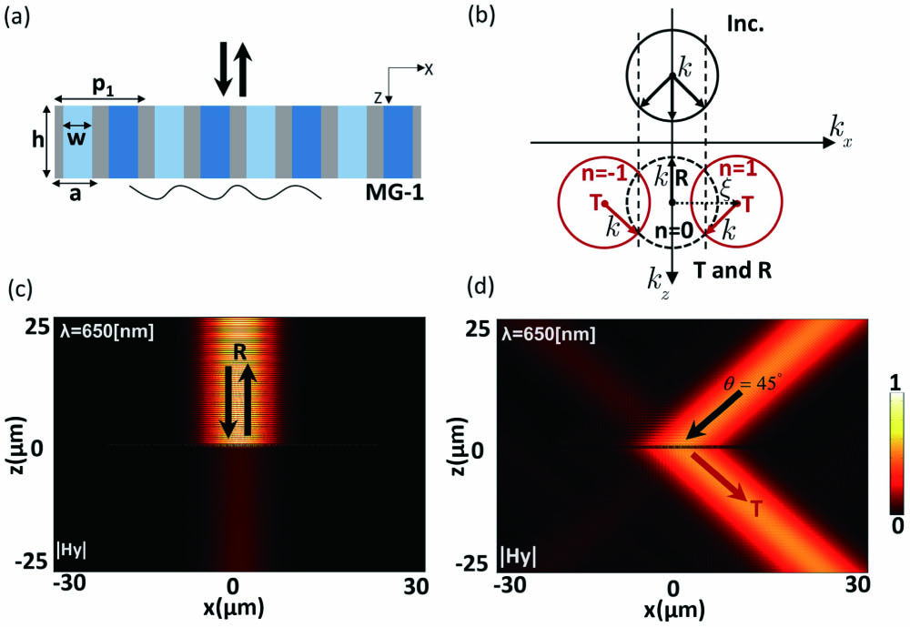
Fig. 1. (a) Structure of designed MG-1, a periodic metallic slit array (gray region) filled with two different kinds of media (colored blue regions) alternatively, forming a supercell containing two unit cells (i.e., m = 2). (b) Iso-frequency diagram indicating all possible diffraction orders. (c) and (d) are the magnetic field patterns for incident light with two different incident angles. The working wavelength is
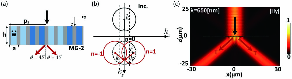
Fig. 2. (a) Structure of designed MG-2, a periodic metallic slit array (gray region) filled with two different kinds of media (colored blue regions) alternatively, forming a supercell containing two unit cells (i.e., m = 2). (b) Iso-frequency diagram indicating all possible diffraction orders. (c) is the magnetic field patterns for normally incident light.
Fig. 3. Structure of designed bi-layer MG system based on MG-1 and MG-2. (a) and (b) schematically show the scattering process for (a) positive incidence (PI) and (b) negative incidence (NI), respectively.
Fig. 4. (a) When the TM wave is incident to the bi-layer MGs, which are filled with impedance-matched material, the relationship curve between the transmission and reflection efficiency and the size of the air gap for PI and NI, respectively. Magnetic field diagram when the air gap with
Fig. 5. (a) Geometric structure of nonmagnetic unit cell for the design of magnetic MGs based on the local Fabry–Perot (FP) resonances. (b) Transmission and phase shift of the unit cell versus the height d of filled dielectric with εd
Fig. 6. Performance demonstrations. (a) Relationship between the transmission/reflection efficiency and the size of the air gap for PI and NI. (b) Magnetic field pattern for PI when

Set citation alerts for the article
Please enter your email address
© Copyright 2018-2021 | Chinese Laser Press. All Rights Reserved 沪ICP备15018463号-20